

The purpose of this paper is to present the development of an optimal design framework for high altitude long endurance solar unmanned aerial vehicle. The proposed solar aircraft design framework provides a simple method to design solar aircraft for users of all levels of experience.
This design framework consists of algorithms and user interfaces for the design of experiments, optimization and mission analysis that includes aerodynamics, performance, solar energy, weight and flight distances.
The proposed sizing method produces the optimal solar aircraft that yields the minimum weight and satisfies the constraints such as the power balance, the night time energy balance and the lift coefficient limit.
The design conditions for the sizing process are given in terms of mission altitudes, flight dates, flight latitudes/longitudes and design factors for the aircraft configuration.
The framework environment is light and easily accessible as it is implemented using open programs without the use of any expensive commercial tools or in-house programs. In addition, this study presents a sizing method for solar aircraft as traditional sizing methods fail to reflect their unique features.
Solar aircraft can be used in place of a satellite and introduce many advantages. The solar aircraft is much cheaper than the conventional satellite, which costs approximately $200-300m. It operates at a closer altitude to the ground and allows for a better visual inspection. It also provides greater flexibility of missions and covers a wider range of applications.
This study presents the implementation of a function that yields optimized flight performance under the given mission conditions, such as climb, cruise and descent for a solar aircraft.
Nomenclature
Symbols
- CD,wing
= wing drag coefficient;
- CL
= lift coefficient;
- Eavailable
= energy storage of fuel cell equals;
- PFC
= fuel cell output;
- Ppayload
= power required for payload;
- Preq
= power required for flight;
- Psolar
= solar power;
- Ptotal
= total power required for flight;
- K
= induced drag coefficient; and
- Sff
= solar cell fill factor.
Definitions, acronyms and abbreviations
- AR
= aspect ratio;
- CFD
= computational fluid dynamics;
- DOE
= design of experiment;
- GUI
= graphical user interface;
- HALE
= high altitude long endurance;
- HPA
= human powered aircraft;
- NASA
= national aeronautics and space administration;
- OpenVSP
= open vehicle sketch pad;
- PV cell
= photovoltaic cell;
- RFC
= regenerative fuel cell;
- SADF
= solar aircraft design framework;
- SBAO
= surrogate-based analysis and optimization;
- UAV
= unmanned aerial vehicle; and
- VBA
= visual basic for application.
Introduction
There is a growing request for a solar-powered high altitude long endurance (HALE) aircraft that performs missions at stratospheric altitudes of 17-25 km. This aircraft can be used in place of a satellite and introduce many advantages. The solar-powered HALE aircraft is much cheaper than the conventional satellite, which costs approximately $200-300m. It operates at a closer altitude to the ground and allows for a better visual inspection. It also provides greater flexibility of missions and covers a wider range of applications (Romeo et al., 2004). Furthermore, it is self-launching, easy to withdraw for maintenance and easy to relocate to cover other areas.
Although the features of the solar-powered electric airplane are promising, they can only be implemented through the successful integration of several essential technologies, which include light, high-efficiency solar energy conversion and storage devices and innovative, ultra-light-weight airframe materials and structural concepts. Furthermore, airfoils, propellers and airplane configurations must yield an efficient aerodynamic performance at the Reynolds numbers of 105 or less (Youngblood and Talay, 1982). The objective of this study is to develop a software that incorporates the elements of these essential technologies in the analysis and design processes of the solar powered flight.
Frulla and Cestino (2008) carried out the research with the aim of designing a HALE unmanned aerial vehicle (UAV) solar-powered platform and manufacturing a scale-sized solar-powered prototype. Zhu et al. (2014) discussed the historical development and the challenges being faced by solar-powered airplanes. Panagiotou et al. (2016) analyzed the efficiency of the solar panels and the efficiency ratios of each component of the power system.
The aircraft sizing process is a critical aspect of the system-level study because it initiates the design and analysis activities, which include internal layout, cost analysis and system effectiveness analysis. For instance, one of the results of aircraft sizing, the initial estimation of thrust or power required, is a primary input to the preliminary investigation of the engine company, particularly if a new propulsion system is jointly developed. The probabilistic aircraft sizing method can be applied to aircraft design optimization problems in which multidisciplinary design parameters such as wing geometry, tail arrangement and propulsion system design parameters are included as design variables. In the optimization problem, the design variables include disciplinary design variables and the original sizing variables. In addition, a number of constraints resulting from decoupling the disciplinary analyzes may be added.
However, no currently available tools provide a comprehensive, systematic and generalized aircraft sizing method, which is applicable to a wide range of unconventionally powered aircraft (Nam et al., 2005).
In the case of a solar energy-based aircraft, the amount of electric energy supply is determined by the wing area, photovoltaic (PV) cell efficiency and solar irradiation. As the available energy is directly related to the wing area, the configuration design and the required electric energy should be considered simultaneously. Because of the interconnection among the configuration, power available and power required, the design process of the solar energy-based aircraft requires a unique approach. This study develops a stochastic approach for the aircraft sizing to solve these problems and applies it to the sizing optimization of a solar HALE UAV. Another achievement of this study is the implementation of the proposed method, which is different from conventional aircraft sizing methods.
It is important for a solar-powered aircraft analysis to account for the ability to reach the mission altitude and the energy balance at high altitudes. This is because the energy sources of this aircraft are solar energy, which is only available during the daytime and fuel cells and batteries, which are used at night. In addition, the analysis of the configuration variables and aerodynamic characteristics seriously demands the employment of surrogate models, which provides fast and approximate solutions. This is because the optimization within the sizing process requires frequent changes to the wing area, aspect ratio and weight, and hence, the recalculation of aerodynamic coefficients. This process can be very costly, as the aerodynamic analysis requires significant computational loads. Although such efforts to enhance computational efficiencies, when the objective and/or constraint functions are evaluated by computationally-expensive analyzes such as computational fluid dynamics, a probabilistic design approach would be computationally intractable. To alleviate such a problem, the so-called surrogate-based approach for analysis and optimization can play a very valuable role. The surrogates are constructed using data drawn from high-fidelity models and provide fast approximations of the objectives and constraints at new design points, thereby making sensitivity and optimization studies feasible. This study reflects these latest techniques and develops a conceptual design optimization tool for a solar-powered HALE UAV. Moreover, this tool enhances the efficiency of the proposed design/development framework.
National aeronautics and space administration also used Microsoft Excel®/Visual Basic and inherent graphical user interfaces for its HALE UAV study (Nickol et al., 2007). It used in-house programs for the aerodynamic and performance analyzes. The analysis components are integrated through ModelCenter and the optimization module. In contrast, this study avoids the use of ModelCenter and uses only Excel/Visual Basic to integrate the optimization and other modules. Although ModelCenter (2014) provides excellent connectivity and integrity in distributed environments, the proposed framework works with only a few different platforms that Excel/Visual Basic can effectively manage. Furthermore, unlike Excel, ModelCenter is not readily available for most users and may demand an extra cost to obtain.
The methods developed in this study was applied to the solar HALE UAV configuration developed in a previous study, which provide information regarding the detailed design procedure of the solar HALE UAV and specific design variable numbers (Joo and Hwang, 2017).
Architecture of the solar aircraft design framework
The solar aircraft design framework (SADF) is configured in a way where the user can efficiently conduct multidisciplinary design and analysis by using the tools that have been already verified and are being widely used. Figure 1 briefly illustrates the architecture and data flows of the SADF and Figure 2 shows the participating tools. The SADF conducts the deterministic optimization using Microsoft EXCEL/Visual Basic and MATLAB’s fmincon function. In addition, the SADF uses MATLAB’s optimization algorithms to implement the reliability-based design optimization (probabilistic optimization) that has been made limitedly available through a few tools such as ModelCenter.
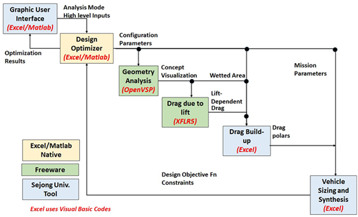
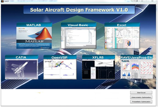
The open vehicle sketch pad® (OpenVSP, 2012) program is used in the SADF for visualization of the aircraft configuration and analysis of the geometry. Another tool that the SADF uses is XFLR5® (XFLR5, 2016), which is used for aerodynamic analysis based on the aircraft’s configuration data.
The vehicle sizing and synthesis block calculates the amount of solar energy at the given flight conditions (latitude, longitude, and takeoff time) and synthesizes the aerodynamic and thrust data for the aircraft sizing under the constraints of energy balance for maintaining flight. This component is implemented using Excel and visual basic for application (VBA) and is able to conduct the fundamental sizing of a solar aircraft independently of the other analytical components.
Contents of solar aircraft design framework
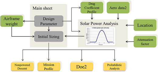
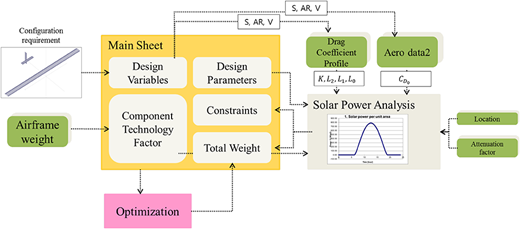
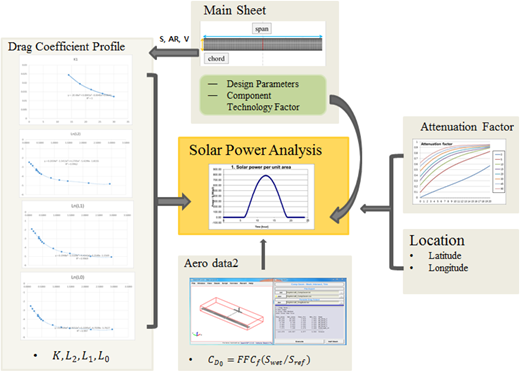
The SADF is capable of conducting deterministic optimization using only Excel and VBA. The Excel module comprises the sheets, which are named DoE2, main, location, attenuation factor, probabilistic analysis, airframe weight, solar power analysis, drag coefficient profile, aero data2, regenerative fuel cell (RFC), climb, descent and mission profile. These sheets conduct individual analysis and the main sheet connects them for synthesis as shown in Figure 3. The main sheet takes the design parameter inputs and provides them to the drag coefficient profile sheet where the aerodynamic coefficients are calculated. Using the calculated aerodynamic coefficients and the other inputs, such as the airfield location, the flight date and the PV cell efficiency, the solar power analysis sheet determines the amount of solar energy that can be used for 24 h. Finally, the calculated solar energy is fed back into the main sheet, which conducts optimization for the minimum weight of the aircraft under the constraints of the power margin, nighttime energy margin and lift coefficient (CL) margin.
Main sheet
The main sheet takes the user input for the Solar-Powered HALE aircraft design parameters and provides the optimized design results. Figure 4 shows a screen capture of the main sheet and Table I shows the configuration parameters, which the main sheet presents.
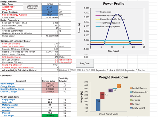
Design variables, design parameters, component technology factors, constraints and weight breakdown in the main sheet
| Design variables | Constraints | Current value | Feasibility criterion | ||
|---|---|---|---|---|---|
| Wing span | 32.86 | m | Power margin | 0.000000 | >0 |
| Aspect ratio | 24.00 | – | Energy margin | 0.622854 | >0 |
| Wing area | 45.00 | m2 | Night time energy margin | 0.000000 | >0 |
| Power available | 0.87 | kW | Cruise CL margin | 0.641136 | >0 |
| Fuel cell energy available | 10.64 | kWh | |||
| Cruise speed | 10.66 | m/s | |||
| Empty weight | 76.2 | kg | |||
| Design parameters | Design parameters | ||||
| Total weight | 165.06 | kg | Solar cells | 22.4 | kg |
| Solar cell fill factor(Sff) | 0.828 | Motor + propeller | 3.9 | kg | |
| Payload power (Ppl) | 360 | W | RFC system | 22.6 | kg |
| Payload mass | 40 | kg | Avionics | 0.0 | kg |
| Avionics system mass | 0 | kg | Payload | 40.0 | kg |
| Maximum allowable CL @ Cruise | 1.5 | – | |||
| Component technology factor | |||||
| Solar cell efficiency | 0.19 | – | RFC specific energy | 470 | Wh/kg |
| Solar cell-specific mass | 0.6 | kg/m2 | Fuel cell efficiency | 0.6 | – |
| Propeller efficiency @ Cruise | 0.83 | – | Electrolyzer efficiency | 0.7 | – |
| Electric motor/prop specific power | 0.0443 | Round trip efficiency | 0.42 | ||
| Electric motor efficiency | 0.9 | Airframe weight adjustment factor | 1 | ||
Notes:
Airframe weight calculation method 1: Heliplat; 2: Calibrated regression; 3: HPA (Human powered aircraft); 4: Regression method 2; and 5: Stender
The design variables show the wingspan, aspect ratio, wing area and the amount of fuel cell energy available of the solar-powered HALE aircraft. The user provides the initial values of the aspect ratio and wing area and starts the optimization by pressing the deterministic optimization button. This button is an implementation of VBA that drives the optimization solver in Excel.
Next, the constraints part shows the current values of the constraint conditions, i.e. the power margin, the daytime and nighttime energies and the Cruise CL margin. These values are expected to be greater than zero to satisfy the constraints.
Finally, the weight breakdown part retrieves the component weights from the solar power analysis sheet. The displayed values are the set of optimum component weights that the deterministic optimization yields under the specified constraints. The procedural flow associated with the main sheet is illustrated in Figure 5.
Drag coefficient sheet
The drag coefficient sheet calculates the aerodynamic drag coefficients based on the specified design variables and the flight conditions. In the early phase of this study, the CD,wing calculation used the quadratic surrogate equation of the CL as shown in equation (1):
where the coefficients K1, K2 and CD,wing,o are expressed as functions of the wing area, the aspect ratio and the flight speed:
These functions are obtained via regression using the JMP, a specialized commercial tool (JMP, 2014). However, since this surrogate model is tailored to a specified altitude, it should be rebuilt when the analysis accounts for other altitudes. This means that all of the aerodynamic coefficients need to be obtained through a significant amount of XFLR5 executions, followed by the regression using the JMP. XFLR5 tends to underestimate the drag force due to viscous effects. A higher-fidelity method could be used to provide more accurate results, but would require considerably more time and resources. XFLR5 may not be the most accurate tool available, but can help save time.
To gain the benefit of using the surrogate model without the impractical process of rebuilding the model, this study uses a new approach to construct the surrogate model. The new surrogate model consists of functions of the Reynolds number and aspect ratio and covers wide ranges of altitudes, speeds, wing areas and wing slenderness ratios. As the model is constructed using only two variables, the regression can be performed easily and quickly, even without the use of specialized commercial tools such as JMP. Furthermore, the new surrogate model consists of a single formula that encompasses a wide range of wing areas. Therefore, it eliminates the possibility of inconsistency and errors that the set of multiple formulas generally experiences. The new surrogate model calculates the induced drag as a quadratic function of the CL with the induced drag coefficient (K), which is calculated using the wing aspect ratio.
Solar power analysis sheet
The solar power analysis sheet determines the possibility of maintaining flight through the energy balance between the available energy from the PV cells and the required energy for daily flight. Given a specific date of the year and the latitude and longitude of a specific location, the power generated by the PV cells for 24 h is calculated. Based on the power available, the program determines the wing loading and feasibility for flight, followed by the gross weight of the aircraft as shown in Figure 6. The user selects the flight location from the 30 representative airfields in South Korea and enters the flight date for the solar energy calculation. Once the Excel VLOOKUP function retrieves the selected data, the system automatically enters the latitude, longitude and the Linke turbidity.
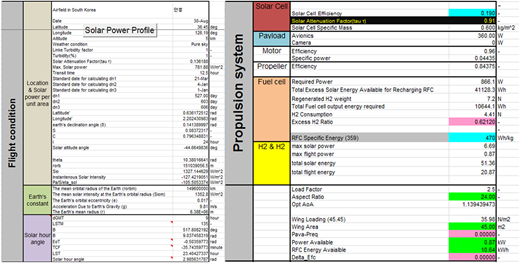
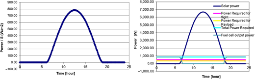
The daily solar power and energy are calculated and visualized from 0:00 to 24:00 at intervals of 0.1 h. The daily power is calculated using the equations and solar energy tables that cover the altitudes of 0-21 km. The fuel cell output power, which is mainly used for nighttime, equals the difference between the power required and solar power available. The fuel cell does not generate power when the amount of solar power exceeds the power required for flight. The daily energy storage of the fuel cell equals Eavailable, which is a parameter for weight estimation of the fuel cell.
Following the previously addressed theories and formulas, Figures 7 and 8 show the profiles of the solar power, Psolar, the power required for payload, Ppayload, the power required for flight, Preq, the total power required for flight, Ptotal and the fuel cell output, PFC.

The weight part estimates the component weights, which include structure, the payload and the avionics and the hybrid propulsion system of the PV cells, the motor, the propellers and fuel cell. Table II presents the weight part.
Weight part in solar power analysis sheet
| Weight | |||
| Structural | We | 1,236.5 | N |
| Payload | Wp | 49.1 | N |
| Avionics | Avionics | 98.1 | N |
| Solar cell | Wsol | 319.3 | N |
| Motor | Wmotor | 122.1 | N |
| Propeller | Wprop | 0.0 | N |
| Fuel cell | RFC system | 618.4 | N |
| H2 | Whyd (Required) | 13.4 | N |
| O2 | Woxy | 106.9 | N |
| H2 tank | N | ||
| N | |||
| Total | Wto | 2,443.4 | N |
| Structural | Empty weight | 126.0 | kg |
| Payload | Payload | 5.0 | kg |
| Avionics | Avionics | 10.0 | kg |
| Complex propulsion system | Solar cells | 32.6 | kg |
| Motor + propeller | 12.5 | kg | |
| Fuel cell system | 63.0 | kg | |
| Total | Total weight | 249.1 | |
In the surrogate model improvement process, the Ks, the parasite drag coefficients and the total drag coefficients are calculated in linkage with the drag coefficient sheet. The sheet provides a comparison of the estimation through the surrogate model and the actual calculation of the aerodynamic model. Figure 9 illustrates the architecture of the calculation flow that is associated with the solar power analysis sheet.
Location and turbidity sheet
The location and turbidity sheet is used to enter the information on the latitudes and longitudes for the given flight locations and the atmospheric turbidity depending on atmospheric conditions. The information on atmospheric turbidity is as shown in Table III.
Attenuation factor sheet
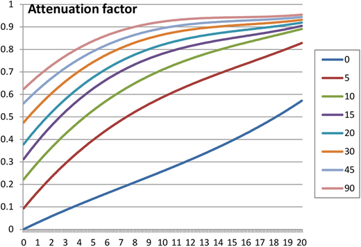
Figure 10 presents the solar attenuation factor along with the flight and solar altitudes.
Airframe weight sheet
The airframe weight sheet provides the weight estimation equations, which the main sheet refers to. The identification numbers 1-4 are assigned to the equations from Heliplat (Romeo, 204), the structural weight of human-powered aircraft, the regressions equations and equations from Stender (Noth, 2008). The Heliplat equations yield better estimations for the twin boom types and heavy aircraft of the 1,000 kg class. The human powered aircraft equations are known to suit the general glider configurations of the 150 kg class, to which the target aircraft of this study belongs. However, this study uses the Stender method that yields conservative results.
DOE_2 sheet
The main sheet determines the optimum combination of design variables that satisfies the three constraint conditions, namely, the power margin, nighttime energy margin and cruise CL margin. In contrast, the optimum combinations for many different flight locations and dates can be found at once on the DOE_2 sheet, which is shown in Table IV. The DOE_2 sheet provides the outputs that correspond to the user’s input sets of ten design variables, namely: flight date, wing area, aspect ratio, PV cell efficiency, PV cell-specific mass, RFC specific energy, fuel cell efficiency, airframe weight adjustment factor, payload and payload power. The outputs are cruise speed, RFC, power margin, energy margin, nighttime energy margin, cruise CL margin, empty weight, solar cell/motor/propeller/RFC system/avionics/payload weight, total weight, required energy, solar energy, lift to drag ratio, required flight power, CL, drag coefficient and vertical tail/horizontal tail area.
DoE_2 sheet
| Day | S | Solar cell-specific mass | RFC specific energy | Airframe weight adjustment factor | Payload weight | Payload power | V | RFC | |||||
|---|---|---|---|---|---|---|---|---|---|---|---|---|---|
| Unit | [m] | AR | Solar cell efficiency | [kg/m^2] | [Wh/kg] | Fuel cell efficiency | [kg] | [W] | Round trip efficiency | [m/s] | [kW h] | Power margin | |
| 830 | 35 | 8 | 0.19 | 0.6 | 470 | 0.6 | 1 | 40 | 360 | 0.42 | 11.74685 | 13.36489 | −9.00711E−08 |
| 35 | 12 | 0.19 | 0.6 | 470 | 0.6 | 1 | 40 | 360 | 0.42 | 11.5125 | 11.93373 | −7.36469E−08 | |
| 35 | 16 | 0.19 | 0.6 | 470 | 0.6 | 1 | 40 | 360 | 0.42 | 11.3666 | 11.115 | −9.38558E−08 | |
| 35 | 20 | 0.19 | 0.6 | 470 | 0.6 | 1 | 40 | 360 | 0.42 | 11.36108 | 10.67784 | −5.91906E−08 | |
| 35 | 24 | 0.19 | 0.6 | 470 | 0.6 | 1 | 40 | 360 | 0.42 | 11.35564 | 10.44875 | −4.41271E−08 | |
| 40 | 8 | 0.19 | 0.6 | 470 | 0.6 | 1 | 40 | 360 | 0.42 | 11.23979 | 13.31474 | −8.80737E−08 | |
| 40 | 12 | 0.19 | 0.6 | 470 | 0.6 | 1 | 40 | 360 | 0.42 | 11.02285 | 11.95361 | −8.76E−08 | |
| 40 | 16 | 0.19 | 0.6 | 470 | 0.6 | 1 | 40 | 360 | 0.42 | 10.96401 | 11.1653 | −6.88E−08 |
| Power margin | Energy margin | Nighttime energy margin | Cruise CL margin | Empty weight | Solar cells | Motor + propeller | RFC system | Avionics | Payload | Total weight |
| [kg] | [kg] | [kg] | [kg] | [kg] | [kg] | [kg] | ||||
| −9.00711E−08 | −0.124685797 | −9.75272E−08 | 0.793895234 | 37.49831619 | 17.388 | 4.780036399 | 28.40694412 | 0 | 40 | 128.0732967 |
| −7.36469E−08 | 0.019803028 | −7.9234E−08 | 0.740191068 | 45.31545915 | 17.388 | 4.300476831 | 25.36502275 | 0 | 40 | 132.3689587 |
| −9.38558E−08 | 0.119710426 | −9.98539E−08 | 0.694063757 | 51.83138032 | 17.388 | 4.023559879 | 23.62483142 | 0 | 40 | 136.8677716 |
| −5.91906E−08 | 0.179516047 | −6.31616E−08 | 0.666074592 | 57.52408917 | 17.388 | 3.874815794 | 22.69564192 | 0 | 40 | 141.4825469 |
| −4.41271E−08 | 0.212854739 | −4.71504E−08 | 0.638442305 | 62.63648709 | 17.388 | 3.796868509 | 22.20871298 | 0 | 40 | 146.0300686 |
| −8.80737E−08 | 0.052623709 | −9.48347E−08 | 0.790867231 | 41.60346486 | 19.872 | 4.806289578 | 28.3003559 | 0 | 40 | 134.5821103 |
| −8.76E−08 | 0.211271016 | −9.35012E−08 | 0.733542366 | 50.27639382 | 19.872 | 4.343423327 | 25.40727986 | 0 | 40 | 139.899097 |
| −6.88E−08 | 0.321140141 | −7.27079E−08 | 0.696024964 | 57.50564904 | 19.872 | 4.073856748 | 23.73174032 | 0 | 40 | 145.1832461 |
| −8.90E−08 | 0.386605889 | −9.42E−08 | 0.668397198 | 63.82157029 | 19.872 | 3.928682093 | 22.83848616 | 0 | 40 | 150.4607385 |
| −6.01E−08 | 0.421187899 | −6.35E−08 | 0.639590685 | 69.49365077 | 19.872 | 3.856319624 | 22.39324263 | 0 | 40 | 155.615213 |
| −7.70008E−08 | 0.224191978 | −8.22739E−08 | 0.790873828 | 45.595939 | 22.356 | 4.848580273 | 28.34723835 | 0 | 40 | 141.1477576 |
| Span | E_req | E_solar | Lift to drag ratio | Required power for flight | Lift Coefficient | Drag Coefficient | H_Tail area | V_Tail area |
| [m] | [Wh] | [Wh] | L/D | [W] | CL | CD | [m^2] | [m^2] |
| 16.7332 | 25,456.7 | 39,945.32 | 28.3699604 | 696.2944132 | 0.706104766 | 0.02488917 | 3.843810122 | 0.981828124 |
| 20.4939 | 22,902.74 | 39,945.32 | 33.89558791 | 590.3211265 | 0.759808932 | 0.02241616 | 3.147636645 | 1.18596499 |
| 23.66432 | 21,427.98 | 39,945.32 | 38.60558669 | 529.1279233 | 0.805936243 | 0.020876156 | 2.732634692 | 1.358060329 |
| 26.45751 | 20,635.83 | 39,945.32 | 42.53009319 | 496.2583644 | 0.833925408 | 0.01960789 | 2.449423513 | 1.509679366 |
| 28.98275 | 20,220.71 | 39,945.32 | 45.45401753 | 479.0335291 | 0.861557695 | 0.018954489 | 2.240365706 | 1.646753454 |
| 17.88854 | 25,596.51 | 45,651.8 | 28.28891853 | 702.0958493 | 0.709132769 | 0.025067511 | 4.392925854 | 1.193762293 |
Climb flight sheet
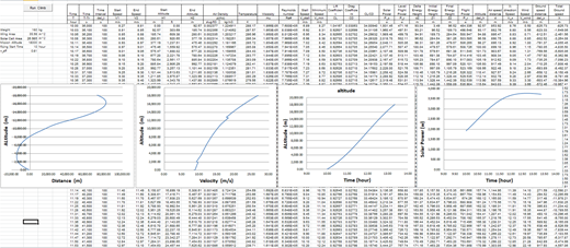
The climb flight sheet provides the mission analysis of the climb from ground level to the specified mission altitude. This sheet design is based on the cruise analysis of the solar power analysis sheet with an addition of elements for the climb that relies only on solar energy. The program considers two climb scenarios: the initial climb from the ground to the mission altitude, i.e. 0-18 km and the climb from the nighttime cruise altitude to the daytime cruise altitude, i.e. 11-18 km. In addition, through the calculated data, the user can investigate the time during, which the aircraft can climb, the available solar energy and power required according to altitude and the total time required to complete the climb as shown in Figure 11.
Descent flight sheet
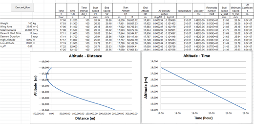
The descent flight sheet provides a similar approach to the climb calculations, except that it uses the fuel cell depending on the descent rate. The target descent rate is assumed constant and is determined as the altitude difference divided by the predefined total time. As the descent does not consume the solar power, the negative energy balance at a given altitude yields an altitude drop or deceleration. The piecewise descent rate is calculated using the altitude drop for each time step and the excessive descent rate from the target value is compensated by the power from the fuel cell. The descent flight sheet is shown in Figure 12.
Mission profile sheet
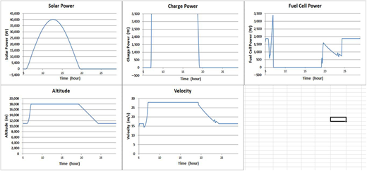
The mission profile sheet provides a comprehensive comparison between the fuel cell energy consumption and available solar energy charge in daily mission profiles, which consist of the climb, cruise and descent. The aircraft consumes power from the fuel cell when it is in descent or nighttime cruise at low altitudes. In contrast, it uses solar power when it is in climb or daytime cruise at high altitudes. The user can also investigate the energy and speed with the total descent time. The calculation starts as the user enters the input variables, such as the descent time and climb start time and clicks the mission flight button. The mission profile result plots are shown in Figure 13.
Conclusion
This study presented a design framework for the initial sizing process of a HALE solar UAV. This design framework can be readily available for most computers as it only uses publicly available programs, i.e. OpenVSP and XFLR5 and Excel and VBA. The user interface of the framework is implemented using Excel, which is user-friendly and can be easily revised on demand. The user interface of the framework shows only the desired outputs on the sheets while the functions and algorithms run behind through Excel and VB environment.
Furthermore, as traditional aircraft sizing methods cannot be applied to a solar aircraft, an adequate sizing approach was developed and implemented. This framework provides an understanding of the effects of the essential components on the weight. Moreover, it enables an easy weight sizing of various solar aircraft to increase PV cell efficiency and fuel cell round trip efficiency. Another benefit of this framework is the aerodynamic surrogate models that enable an optimum design without repeated invocations of the aerodynamic analysis tools for changes in design variables and flight conditions. The framework also provides an analysis of the daily mission profile, which consists of the climb, cruise and descent, for specified configurations and conditions.
In addition, the deterministic optimization, which runs with the visual basic based algorithms, yields the minimum weight of the aircraft that satisfies the constraints. In contrast, the stochastic optimization, which retrieves the MATLAB functions, enables optimized sizing under the uncertainties of the design variables. In summary, this framework is useful and efficiently used in the design of the HALE solar UAV.
In this research, we used low-fidelity tools such as XFLR5 and OpenVSP so that the drag should be corrected by comparing with the real accurate wind tunnel test data. Also, in this research, the Stender method was used for the weight prediction, which usually overestimate the total structural weight. The new weight estimation method should be used after comparing the weight with the actual solar HALE UAV. Hence, higher fidelity methods for drag calculation and weight estimation should be studied to yield a considerably more optimized design with far less error.
This research was supported by the Research Grant from Sejong University through the Korea Agency for Infrastructure Technology Advancement funded by the Ministry of Land, Infrastructure and Transport of the Korean Government (Project No.: 16CTAP-C114866-01).

