

Tandem wing aircrafts belong to an unconventional configuration. It consists of two pairs of similar wings generating lift. System is characterised by strong aerodynamic coupling between wings. The flow around this configuration is very complex and difficult to model in the CFD software. This study aims to investigate the impact of flow modelling on resulting aerodynamic coefficients. Mainly, the coefficients obtained by two different independent software were analysed. Their value and course for complete aircraft and for both wings as well. Moreover, during analysis, different positions of the rear wing were considered as well. This research seeks new insights into method of modelling the flow around aircraft in the tandem wing configuration, to find the best methodology for aerodynamic analysis of the aircraft in the tandem wing configuration.
The methodology used in this work is focused on two advanced commercial CFD software: Ansys-Fluent (www.ansys.com/products/fluids/ansys-fluent) and MGAERO (MGAERO, 2011). The first one uses advanced RANS method. The second one uses the Euler’s equations and the multigrid scheme to solve the arbitrary configuration. The computation by first method is very time-consuming and needs a lot of time to prepare the model. The second method is less time-consuming but has less accuracy. Comparison of the results obtained by both methods allows to assess the methodology impact on the aerodynamic coefficients.
This paper presents the results obtained by two independent software. Analysis reveals that similar results are obtained for lower angles of attack, but for higher angles the discrepancies arise. This is caused by unsteady effects close to the stalling which cannot be considered in MGAERO. In addition, consistency in total coefficients is not always followed by consistency for both wings separately. Above conclusions indicate that simpler software can be used for preliminary analysis of a tandem wing, but for the details of the aerodynamic coupling between the wings, a more advanced approach is necessary, despite the high computational cost.
Obtained numerical results are necessary for further research on the tandem wing configuration, which will be focused on the wide range of wind tunnel tests.
This study shows the comparison of two methods of flow field modelling. This research offers a novel perspective on tandem wings’ analysis, providing valuable insights that extend the current understanding of mutual aerodynamic coupling between the wings. Contrary to the most common approach, not only the impact the front wing has on the rear wing is considered, but also the opposite and that reveals the differences in modelling for different software. The study’s findings highlight the areas for future research.
Nomenclature
- AoA
= angle of attack;
- CDf
= drag coefficient for front wing;
- CDr
= drag coefficient for rear wing;
- CD
= total drag coefficient;
- CLf
= lift coefficient for front wing;
- CLr
= lift coefficient for rear wing;
- CL
= total lift coefficient;
- CMf
= moment coefficient for front wing;
- CMr
= moment coefficient for rear wing;
- CM
= total moment coefficient;
- CoG
= centre of gravity;
- CoP
= centre of pressure;
- CP
= pressure coefficient;
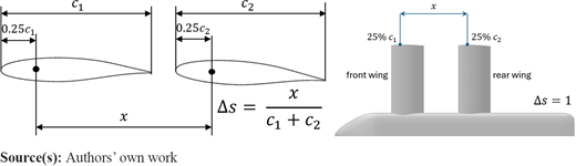
- Δs
= stagger;
- τf
= front wing’s incidence angle; and
- τr
= rear wing's incidence angle.
Introduction
Aerospace engineering, like any field of technology, is subject to constant development, which involves the search for new solutions. The case of aviation is special in that the first aeroplanes were not constructed according to what we now call a conventional configuration, which assumes that the aeroplane has a fuselage, wing and empennage located close to the rear end of the fuselage (Figat, 2022). For example, the well-known Wright brothers’ first aircraft was constructed in a canard configuration (Margański, 2011; Galiński, 2016; Glass and Kubalańca, 2013), i.e. the horizontal tail was placed in front of the main wing. This shows that in aviation, the search for innovative solutions may be based on ideas invented a long time ago but pushed aside, e.g. because of the lack of tools appropriate for analysing aircrafts with a strong aerodynamic coupling.
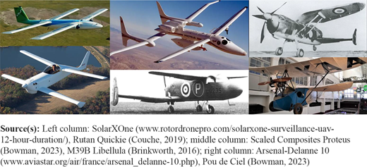
A similar story is related to another unconventional aircraft configuration − a tandem wing. One of the first structures of this type – unmanned Langley Aerodrome − was built at the end of the 19th century. The first manned tandem wing to successfully fly was Blériot VI in 1907 (Minardo, 2014). Figure 1 shows other examples classified as tandem wings.
Background
Although the tandem wing configuration initially developed parallelly with aeroplanes in other arrangements, it is problematic to find one universally accepted definition. According to one definition, tandem wing is an aircraft that uses two independent wings to generate lift, thereby eliminating the need for a tail stabiliser. In addition, both wings have comparable aspect ratio and are usually placed on two different planes (Minardo, 2014). One could argue whether the definition should mention comparable span rather than aspect ratio. Additionally, some claim that tandem wings should not be a separate category, since conventional aircrafts are also tandems as they have two surfaces behind one another (Stackhouse, 2006; Simons, 2019). But a main attribute differing tandem wings from conventional aeroplanes is strong aerodynamic coupling (Stinton, 1993; Kaya, 2019; Shi et al., 2023; Goetzendorf-Grabowski and Figat, 2017; Goetzendorf-Grabowski, 2023), which makes it impossible to use superposition (Fiszdon, 1961; Roskam and Lan, 1997) − e.g. lift coefficient is not the same for each wing (Rokhsaz and Selberg, 1986; Jinbin et al., 2016) and the lift curve for the rear wing is fully nonlinear (Kania, 2024).
What rises the computational cost for tandem wings even more is that at near-stall angles of attack (AoA), the flow is highly unsteady. This phenomenon has been observed in the experimental conditions (Jones and Cleaver, 2015; Zaman and McKinzie, 1988), but thus far no attempt has been made to explain physical groundings behind it.
Despite problems with calculations, tandem wings have many advantages in comparison with a conventional aircraft, like reduced wings span. That makes it more compact and reduces the bending moment, allowing for lighter structure. Another advantage is stall delay (Minardo, 2014; Rokhsaz and Selberg, 1986), which can be obtained thanks to the downwash, i.e. the negative AoA induced behind a front wing on a rear wing (Hall, 2022). This phenomenon, together with upwash, i.e. positive angle induced in front of a rear wing on a front wing (Brown, 2020; Hopkins and Carel, 1951), shows how wings mutually influence each other in a tandem wing.
Another advantage of a tandem wing is reduced induced drag (Cheng and Wang, 2018; Olson and Selberg, 1976; Yazdi, 1991; Jones and Cleaver, 2015; Fanjoy and Dorney, 1996; Zhang et al., 2023). Depending on the details of the design, total drag may not be reduced (Nikhil et al., 2022). This confirms the need for the research regarding tandem wings. Especially since the strong interference between the wings makes it impossible to use the same calculation methods as for conventional aircrafts. Even for more advanced approaches (e.g. Computational Fluid Dynamics – CFD), it cannot be stated that the results obtained from one method are reliable without verifying them, e.g. by comparing with another method. As such, the need for developing a reliable tool for analysing tandem wings arises.
Research aims
The main goal of this research is to check the correctness of two numerical models in the field of the aerodynamic coupling between both wings in a tandem wing configuration. The analysis is focused on a numerical model similar to the model planned to be built for aerodynamic tests in a wind tunnel for further verification. The variable parameters in the calculations are AoA and nondimensionalised streamwise distance between the wings called stagger (Δs; Figure 2). The results in the form of aerodynamic coefficients were compared between two software.
Methodology
The subject of the analysis were the aerodynamic characteristics in the range of AoA from −4° to 25°. Such a choice of the range was dictated by the fact that both practical and near-stall AoA were considered. The aeroplane is in a clean configuration (without controls). Calculations were conducted for two software – MGAERO and Ansys Fluent. Stagger (Δs) was changed by moving the rear wing, with considered positions shown in Figure 3(a).
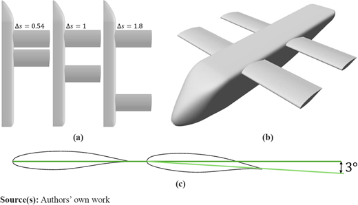
(a) Considered positions of the rear wing, (b) the overall geometry of the aircraft and (c) the incidence angle of the rear wing
(a) Considered positions of the rear wing, (b) the overall geometry of the aircraft and (c) the incidence angle of the rear wing
The geometry of the model was first created in a CAD software [Figure 3(b)] as follows:
the span b = 1.5 m, mean aerodynamic chord and aerofoil are the same for both wings;
the reference length for the moment coefficient (CM) is the sum of chords (2c = 0.556 m);
the reference surface for the lift (CL), drag (CD) and moment coefficients is the combined surface of both wings, hence S = 0.835 m2; and
the incidence angle for the front wing is τf = 0° and for the rear wing τr = 3° [Figure 3(c)].
For the calculations, two software were chosen: MGAERO and Ansys Fluent. MGAERO is a software used for preliminary aerodynamic analysis. It uses Euler’s equations and multigrid scheme to compute the flow field around the aircraft (MGAERO, 2011). In comparison with Ansys Fluent, MGAERO is a simpler software, generally giving less accurate results, but the computational cost is incomparably lower. Figure 4(a) shows surface grid used for calculations. The model consists of Multigrid blocks: 7 levels and surface mesh. They comprise around 35,000 on-body panels and 4 500,000 off-body panels. Thanks to the blocking approach, the mesh stays consistent between different cases of Δs and that makes the calculations more reliable (Mavriplis, 1992).
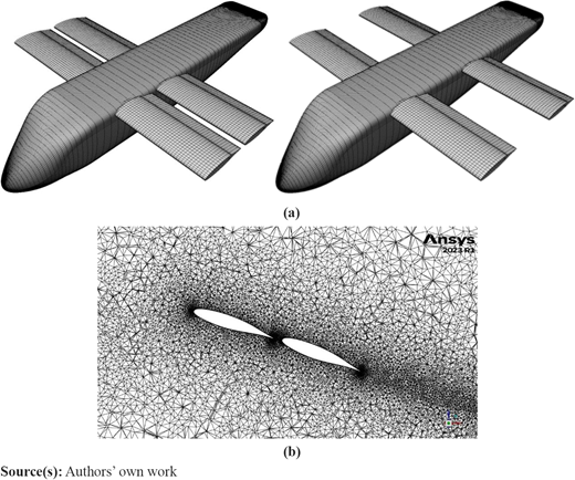
Ansys Fluent is a more advanced software for simulating the fluid flow using Reynolds-Averaged Navier-Stokes (RANS) equations. The strong aerodynamic coupling causes unsteadiness in the flow at AoA > 10°, thus the calculations in Ansys Fluent are transient. Consequently, the computational cost is extremely high and a limited number of values of Δs is considered: 0.54, 1 and 1.8 [see Figure 3(a)]. Furthermore, the aerodynamic characteristics consist of two curves: one corresponding to the maximum value of a given coefficient reached for a given AoA and the other to the minimum.
In Fluent, the flow is viscous. A two-equation Generalize k-ω (GEKO) turbulence model with the Curvature Correction option was used. For this analysis, the parameters of the model were set at values giving results similar to the SST (Shear Stress Transport) k-ω model (Menter et al., 2021). As an additional verification, some computations were performed also for one-equation Spalart−Allmaras (S-A) model. In general, the results from both turbulence models are similar within acceptable tolerance, i.e. for steady AoA, the aerodynamic coefficients are nearly identical. For unsteady AoA, the amplitude of the oscillations is bigger in the case of the S-A model, but the difference in the average values never exceeds 8%. Figure 4(b) shows close-up on mesh used for calculations in Ansys Fluent (around 13 million elements). Thanks to imposing AoA by rotating part of the mesh, changing Δs requires generating anew only this fragment.
Apart from the calculations for the geometry above, some consideration was also given to the 2D case of two symmetrical aerofoils in tandem. From there, it is concluded that increasing the velocity of the undisturbed flow dampens the oscillations significantly, but never disposes of them entirely. The calculations in Fluent for a 3D case were conducted with a freestream velocity of .
The frequencies of oscillations vary between different Δs and AoA. They are in most cases well above 1 Hz. That begs the question whether the changes of aerodynamic coefficients with time would affect the actual flight, because those changes occur fast with a relatively small amplitude, so they may not even be acknowledged by the pilot. Thus, it would be desirable to conduct aerodynamic analysis for a tandem wing without resorting to computationally costly transient calculations. That is why the search for a simpler yet reliable software is vital. For this paper, the software chosen for comparing with Fluent is MGAERO, as introduced before.
Results
Figure 5 shows the pressure coefficient (CP) distribution for two positions of the rear wing. The comparison of both cases is conducted independently for both software, because different colour scales are applied. In addition, for Fluent only the distribution from an arbitrarily chosen moment of time is shown, because for the considered case the amplitude of oscillations is relatively small, so analysing the pressure distributions from more points in time would not provide more information about the flow. As can be seen, the distributions in Figure 5 are enough to conclude that changing Δs visibly affects not only the rear wing, but also the front wing, while in the literature, the impact the rear wing has on the front wing is often omitted. It also can be clearly observed that when the wings are put further apart, the CP distribution on both wings becomes increasingly similar. Above conclusions apply to both analysed software.
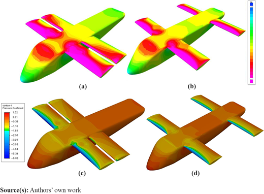
CP distribution at AoA = 15° from MGAERO for Δs (a) 0.54, (b) 1.8 and from Fluent for Δs (c) 0.54, (d) 1.8
CP distribution at AoA = 15° from MGAERO for Δs (a) 0.54, (b) 1.8 and from Fluent for Δs (c) 0.54, (d) 1.8
Total coefficients
Figure 6 shows the comparison of coefficients for three values of Δs and the percentage difference between the average results for exemplary Δs = 1, where positive values indicate that MGAERO is giving a higher result. Like said before, the characteristics for Fluent consist of two curves – one for maximum and one for minimum values reached in the oscillations. For small AoA (below 10°), CL from both models is similar [Figure 6(a)-(c)], with maximum difference of 2.5%. For higher AoA, the difference reaches 10% [Figure 6(j)]. A likely cause of the increasing discrepancy is the fact that above 10° transient calculations in Fluent become necessary. Both software predict high critical AoA. That confirms that stall delay is achieved. As for CD, MGAERO gives significantly lower drag than Fluent [Figure 6(d)-(f) and 6(k)], which is expected for a simpler software (with Fluent being based on RANS equations and MGAERO – on Euler’s equations, so the simplifications coming from the method used give lower drag from MGAERO than from Fluent).
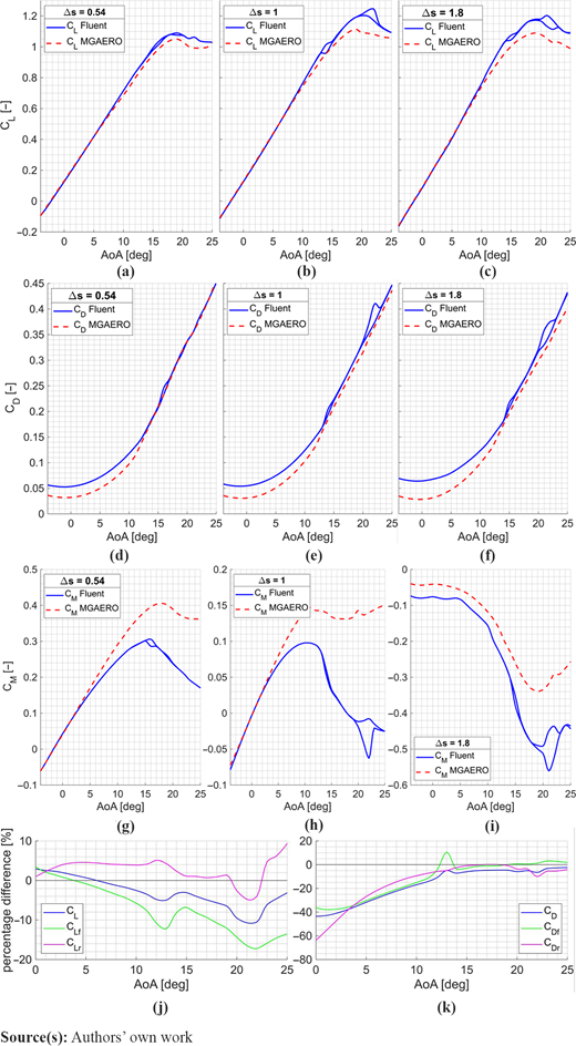
Total lift, drag and moment coefficient comparison for Δs = (a) (d) (g) 0.54, (b) (e) (h) 1, (c), (f) (i) 1.8 and percentage difference between the results for Δs = 1 for (j) lift and (k) drag
Total lift, drag and moment coefficient comparison for Δs = (a) (d) (g) 0.54, (b) (e) (h) 1, (c), (f) (i) 1.8 and percentage difference between the results for Δs = 1 for (j) lift and (k) drag
Small differences in CL between two models translate to similar results for CM for AoA below 4°, but the results quickly diverge [Figure 6(g)-(i)]. Since the forces are similar between both software, the differences must stem from different centres of pressure (CoP). This prompts the hypothesis that unsteadiness in Fluent does not only affect the magnitude of the forces, but also the point they are applied at, i.e. even if an AoA seems steady because CL and CD do not change with time, CoP may be travelling. The same conclusions apply for all cases of Δs.
Unsteady calculations in Fluent reveal some untypical deviations in the shapes of the aerodynamic characteristics. For example, in Figure 6(e) the maximum CD at AoA = 22° visibly stands out and it is higher than CD at AoA = 23°. This abnormality is more visible in CM [Figure 6(h)]. Although seemingly this may be deemed a numerical error, conducting additional calculations around this AoA dismisses this possibility. From analysing the velocity field, it turns out that at this point the rear wing switches with time between full separation and no separation. This can also be observed in Figure 7(b). Similar conclusions can be drawn for other considered cases where abnormalities in characteristics appear. Nevertheless, without the verification of the results from testing a physical object (e.g. wind tunnel tests), it cannot be unequivocally stated whether those oscillations between stall and lack of stall are a physical phenomenon and not a shortcoming of numerical modelling.
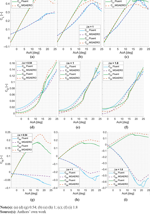
Coefficients for each wing separately
From analysing CL separately for each wing [Figure 7(a)–(c)], the difference between the results from both software in total lift stems mostly from the front wing. In the literature, the impact of the front wing on the rear wing is often focused on while the opposite effect is neglected. But from gathered data, it seems that simpler software does not struggle with predicting correct results for the rear wing. Instead, it significantly underestimates the positive impact the rear wing has on CLf.
There are two unsteady ranges of AoA for calculations in Fluent. For CLf, the first unsteady range coincides with a phenomenon resembling stalling, but further CLf keeps on increasing and the second unsteady range coincides with actual stall. Such behaviour for a tandem wing has already been observed in the literature and it is called secondary stall (Shah and Ahmed, 2024).
MGAERO unexpectedly predicts higher CDf at higher AoA. The reason behind this is probably because upwash from the rear wing reduces CDf. This effect is captured by Fluent, but not by MGAERO. This confirms the earlier conclusion that MGAERO correctly models the effects of the impact the front wing has on the rear wing, but not the opposite. Analysing CMf and CMr shows that for both wings, MGAERO predicts higher values. The conclusions from comparison are the same for Δs = 0.54 and Δs = 1.8 [Figure 7(d)–(i)]. Untypical behaviours at near-stall and post-stall AoA coincide with what was described for total coefficients, i.e. although hypotheses can be formulated as to where those abnormalities come from, they cannot be confirmed nor denied without verification by wind tunnel tests.
Conclusion
In this paper, the aerodynamic analysis for the aircraft in a tandem wing configuration is presented. The main goal of the research was to determine whether the effects of mutual aerodynamic impact of the wings in a tandem wing configuration are modelled similarly by two software (Ansys Fluent and MGAERO). Calculations in Fluent had to be conducted as transient and that led to high computational cost. On the other hand, MGAERO is generally considered less accurate, e.g. as shown in comparison with wind tunnel tests data in Waller (2002), but the computational cost is much lower. The main conclusions from the analysis are:
Both models give similar lift for AoA up to 10°. Beyond that transient calculations in Fluent become necessary and discrepancies between the models arise. MGAERO gives lower drag for all AoA.
Both models give similar aerodynamic coefficients for the rear wing for all AoA, especially the lift coefficient. As for the front wing, MGAERO predicts lower lift and higher drag, which means that it underestimates the positive impact the rear wing has on the front wing.
Unsteadiness in Fluent applies not only to the magnitude of the forces, but also to the centre of pressure for each wing. That causes differences in the moment coefficient between the models.
Further work
The differences between the results from both software highlight the need for conducting wind tunnel tests for further verification. Especially because without the third source of results, it cannot be unequivocally confirmed nor denied that results from one software are more accurate than from another. Even though Fluent is generally a more advanced software than MGAERO, it is not specialised for analysing aircrafts. As such, it may turn out that it overestimates the impact the rear wing has on the front rather than MGAERO underestimating this effect. Furthermore, more calculations from both software are needed to further study the mutual aerodynamic impact of the wings. More cases of Δs should be considered in Fluent and deeper analysis into the unsteadiness and causes behind it is required. Last but not least, the calculations for a tandem wing with flaps and ailerons on both wings are planned because performance for such a strongly aerodynamically coupled configuration should be analysed under trim conditions. The model for wind tunnel tests is also going to be equipped with control surfaces. This will ensure proper verification and will allow to ultimately create a reliable model of an aircraft in a tandem wing configuration.
