This paper describes a method to construct a movable virtual sound source (VSS) from a linear array of parametric loudspeakers. In the proposed method, wave field synthesis is used to construct a focused VSS at any position in air without moving the loudspeakers. The motion of the VSS can be realized by constructing VSSs successively along the moving path. Parametric loudspeakers realize a sharp directivity by exploiting the straightness of ultrasound; therefore, a VSS constructed by the proposed method is expected to be easy to perceive. Compared with a VSS constructed from conventional electro-dynamic loudspeakers, the proposed method can achieve a higher precision when the VSS is moving parallel to the loudspeaker array.
1 Introduction
Due to the rapid development of film and video technology in recent years, the demand is rising for three-dimensional sound field reproduction technologies. For example, multichannel surround-sound systems [11, 15] have been proposed. In these systems, electro-dynamic loudspeakers (EDLs) are arranged around the listener, and virtual sound sources (VSSs) are constructed with amplitude panning [7, 18] based on human auditory characteristics. In addition to EDLs, parametric loudspeakers [4, 8, 21] have also been used in surround-sound systems [12, 22, 26]. The parametric loudspeaker is an application of a parametric array [8, 28] to reproduce audible sound. It can realize a sharp directivity by using ultrasound and, therefore, it can be used in audio spotlights [13, 16, 29], three-dimensional sound field reproduction [14, 17, 25], and active noise control [27]. Although the reproduced sound of parametric loudspeakers has drawbacks, such as poor low-frequency reproduction and harmonic distortion [9, 10, 20], it should be stressed that the sound image constructed by parametric loudspeakers is sharper than that constructed by EDLs [12, 22, 26]. In surround-sound systems using EDLs or parametric loudspeakers, the direction of the VSS can be perceived if the listener stands at the so-called “sweet spot”; however, these systems have a common drawback in that the sweet spot is too small for multiple users. Other VSS construction methods that use the sharp directivity of parametric loudspeakers have been proposed. For example, VSSs can be constructed using the sound of parametric loudspeakers reflected by walls or other obstacles [14, 25]. It is easy to construct a VSS on walls, ceilings, and floors with these methods, but it is difficult to construct the VSS at an arbitrary position in the air.
We have previously proposed a VSS construction method based on a focal point formulation using a parametric loudspeaker array (PLA) [17]. In this method, the PLA is a linear array with a specified interval between loudspeakers, and the placement angles are controlled with pan-tilt units. A focused VSS can be constructed in the air by focusing the ultrasound emitted from the PLA, and the desired radiation characteristics of the VSS can be reproduced by controlling the power and time delay of the signals emitted from the PLA. However, the construction of a moving VSS is limited by the mechanical performance of the pan-tilt units, because they are required to control the direction of the loudspeakers with rapid speed, high accuracy, and low noise level. To solve the problems of our previous method, we focused on wave field synthesis (WFS) technology [1, 6], which is a spatial sound field reproduction technique based on a physical acoustic model [5]. WFS can be used to reproduce the target sound field in a different space based on the signals observed in the target field [6]. Moreover, the desired sound field can be synthesized with suitable driving functions even if the target field does not exist.
In this paper, we propose a method for constructing a movable VSS based on WFS using PLA. We demonstrated previously that parametric loudspeakers can be used as secondary sound sources in sound field reproduction based on WFS [19]. In this study, we used parametric loudspeakers as the secondary sound sources in WFS and constructed a focused-point sound source between the PLA and the listener. The motion of the VSS is realized by switching the driving functions in time frames [3], and crossfade processing is performed to smoothen the auditory perception of the motion. We also carried out evaluation experiments with constructed stationary and moving VSSs to demonstrate the effectiveness of the proposed method.
2 Proposed VSS Construction Based on WFS using PLA
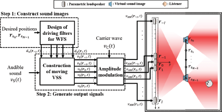
In this paper, we propose a construction method for movable VSSs based on WFS using a linear PLA. An overview of the proposed method is shown in Figure 1. As shown in Figure 1, the processing of the proposed method can be divided into two steps. In Step 1, driving filters are designed to construct a VSS with the WFS method at positions along the desired moving path. In Step 2, output signals are generated with the target audible sound υs(t) and driving filters designed in Step 1. The VSS motion is realized with cross-fade processing, which switches driving filters for each position along the moving path.
In Figure 1, the constructed VSS moves from the initial position to the final position . If a uniform rectilinear motion is assumed, a typical position along the moving path, , can be expressed by the following:
Section 2.1 describes the design of driving functions with WFS. Section 2.2 explains the construction of a moving VSS with the proposed method.
2.1 Driving Function Design for VSS Construction
2.1.1 WFS Model Definition
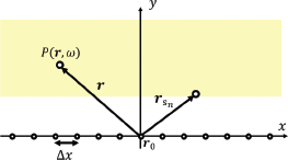
In the proposed method, we use two-dimensional WFS to construct a movable VSS in the xOy plane, and the coordinate system is shown in Figure 2. In the half-space y > 0, the following holds:
where P(r,ω) denotes the sound pressure of angular frequency, ω = 2πf (f denotes the frequency) at position r = [x,y]T, D2D(r0,ω) denotes the two-dimensional driving function of a secondary sound source at r0, and G2D(·) denotes the two-dimensional Green’s function. The driving function D2D(r0, ω) can be obtained with the Rayleigh integral of the first kind, which is given by
where S(r, ω) denotes the wavefront of the VSS. Green’s function G2D(r–r0, ω) can be expressed as
where denotes the imaginary unit, denotes the zero-order Hankel functions of the second kind, and k denotes the wavenumber.
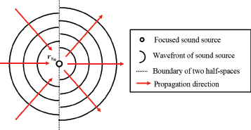
In the proposed method, we construct a focused sound source as VSS. As shown in Figure 3, the sound field converges in one half-space towards the focal point and diverges in the other half-space. The wavefront of focused sound source at can be given as
where c denotes the speed of sound and denotes the zero-order Hankel functions of the first kind.
Equation (5) is substituted into Equation (3) to expand the driving function for VSS construction at as
where denotes the first-order Hankel functions of the first kind and yref denotes the distance from the secondary sound source to the reference line.
2.1.2 Discretization of Driving Functions
Discretization of the secondary sound source can be realized by spatially sampling the driving functions [23]. The discrete driving functions can be expressed as
where δ(·) denotes the Dirac delta function and Δx denotes the interval of secondary sound sources. The wavenumber-domain expression of the driving function can be obtained by a spatial Fourier transform:
where kx denotes the wavenumber on the x-axis.
The wavenumber spectra of driving functions without discretization and with discretized driving functions are shown in Figure 4(a) and (b). In Figure 4(b), it can be seen that spatial aliasing occurs when the secondary sound sources are replaced with loudspeakers. The spatial aliasing frequency is 0.85 kHz under this condition. To eliminate the spatial aliasing in the band above ƒalias, local sound field synthesis [2] is carried out. The wavenumber spectra of the processed driving functions are shown in Figure 4(c). The wavenumber-domain driving functions are converted to frequency-domain driving functions by inverse spatial Fourier transform.
Finite-length truncation is then carried out by applying a rectangular window to the secondary sound sources [24]. The truncated driving functions can be shown as
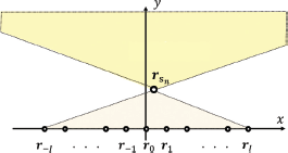
where i = —I, —I +1, · · · I denotes the loudspeaker index. Due to the truncation error, the area where the sound field can be reproduced is limited, as shown in Figure 5.
Finally, the frequency-domain driving functions Dn(r¿,w) are converted to time-domain driving functions dn(rı,t) by inverse discrete Fourier transform, which can be expressed as
where IDFT[·] denotes the inverse discrete Fourier transform. These designed driving functions dn(ri,t) are used in moving VSS construction in Step 2.
2.2 Moving VSS Construction with the Proposed Method
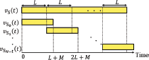
To realize VSS motion, the audible sound υs(t) is first divided into frames with frame length L and overlap length M, as shown in Figure 6. A certain frame can be obtained by
Frame with index n corresponds to the audible sound reproduced by a VSS with position vector ; therefore, it should be convolved with corresponding driving functions. The audible sound reproduced from a loudspeaker at ri in an n-indexed frame can be expressed as
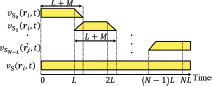
where * denotes the convolution operator. The frames of audible sound reproduced from a certain loudspeaker can be integrated under crossfade processing, as shown in Figure 7. The crossfade-processed frames can be expressed as
where the crossfade coefficients wCF(n,t) can be given as
The integrated signal υs(ri,t) for a loudspeaker at ri can be obtained as
Finally, the audible sound is converted into ultrasound by amplitude modulation and emitted from the linear PLA. The modulated wave using single sideband modulation can be given as
where υ′s(ri,t) denotes the signal υs(ri,t) after a phase shift of π/2 and υ′c(t) denotes the signal υc(t) after a phase shift of π/2. After this processing, the modulated wave is emitted from each parametric loudspeaker in the linear PLA.
3 Evaluation Experiments for Stationary VSS Construction
To demonstrate the effectiveness of the proposed method, we carried out evaluation experiments for constructing a stationary VSS. The synthesis of wavefronts when using WFS with PALs was confirmed in our previous work [19]; therefore, we focused on the sound pressure distribution to confirm whether a VSS had been constructed. Moreover, we measured the inter-aural level difference (ILD) and inter-aural cross correlation (IACC) to evaluate the perception of a VSS.
3.1 Objective Evaluation of Sound Pressure Distribution
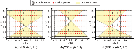
The experimental conditions and equipment are listed in Tables 1 and 2, respectively. The experimental setup is shown in Figure 8. A linear PLA consisting of 23 parametric loudspeakers positioned at intervals of 0.15 m was used in the experiments. The reference line was set at y = 2.5 m. Under this arrangement, the theoretical spatial aliasing frequency was 1.143 kHz. Because the local sound field synthesis [2] was used for spatial aliasing elimination, a wideband white noise of 0–8 kHz was used as the sound source. In Figure 8, microphones are placed at intervals of 0.2 m in the x-axis and 0.25 m in the y-axis. We set 3 patterns for the VSS position at (0, 1.0), (0, 1.5), and (−0.5, 1.0), as shown in Figure 8. We also prepared two cases of the VSS construction method in addition to the proposed method: “Real” stands for constructing the VSS by placing an EDL (FOSTEX, FE83En) at the VSS position and “EDL-WFS” stands for constructing the VSS with EDLs instead of the PLA. In the EDL-WFS case, the arrangement of EDLs is the same as the arrangement of parametric loudspeakers, and the signals expressed by Equation (16) are emitted from corresponding EDLs.
In this experiment, the sound pressures at microphone positions were calculated from the observed signals, as expressed by the following:
where Pob(r) denotes the observed sound pressure at position r and sob(r,t) denotes the observed audible signal at position r. Note that, in the proposed method case, the observed signal includes ultrasound; therefore, a low-pass filter was used to cut the inaudible band before the calculation of Equation (18).
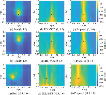
The normalized results for the sound pressure distribution are shown in Figure 9. The cross mark in each panel of Figure 9 shows the position of the constructed VSS, rs. It can be confirmed that both the proposed method and EDL-WFS concentrated the sound pressure at the VSS position. Figure 9(b), (e), and (h) show that the sound pressure attenuates as y increases, which is a typical phenomenon for EDLs. In contrast, Figure 9(c), (f), and (i) show that the sound pressure increases and then decreases as y increases. This can be explained by the energy accumulation of the demodulated sound in the self-demodulation of the parametric loudspeaker. It can also be seen that the proposed method achieves a significant sound pressure difference along the x-axis, which implies that the proposed method can lead to high precision in the sound image localization in the x-axis direction. Because the proposed method shows a concentration pattern of sound pressure at the VSS position, and a radiation pattern of sound pressure in the area y > ys, the proposed method is confirmed to realize VSS construction.
3.2 Objective Evaluation of Sound Image Localization
The experimental results in Section 3.1 suggest that the proposed method may achieve high precision in sound image localization; therefore, we measured the ILD and IACC of each sound field. The experimental conditions and equipment were almost the same as those shown in Tables 1 and 2.
To measure the ILD, a binaural microphone (NEUMANN, KU-100) was placed at intervals of 0.5 m along both the x-axis and y-axis. The ILD can be calculated as the difference in sound pressure between the left and right channels of the binaural microphone, which can be expressed as
where sob,R(r,t) denotes the signal observed by the right channel of the binaural microphone placed at r and sob,L(r,t) denotes the signal observed by the left channel of the binaural microphone placed at r.
The experimental results for the ILD distribution are shown in Figure 10. As in Figure 9, cross marks show the positions of the constructed VSS, rs. It should be noted that in this experiment, the binaural microphone faced the loudspeaker array; therefore, the right channel of the binaural microphone had a lower x-coordinate value than did the left channel. In the area x < xs, the left channel of the binaural microphone was closer to the VSS; therefore, the ILD value was expected to be positive. In contrast, in the area x > xs, the ILD value was expected to be negative. It was confirmed that both the proposed method and EDL-WFS show a similar tendency to that of the Real case. Therefore, both the proposed method and EDL-WFS can approximately reproduce the ILD characteristics of Real.
When measuring the IACC, a binaural microphone (Neumann, KU-100) was set at rref = [0 2.5]T and at rS. The IACC can be calculated as follows:
A higher IACC value indicates a more focused sound image; therefore, the IACC can be used to evaluate the precision of sound image localization.
The results for the IACC measured at yref are shown in Table 3, and the results for the IACC measured at yS are shown in Table 4. It can be confirmed that the proposed method achieved a higher IACC than EDL-WFS did in all cases. This can be explained by the parametric loudspeaker having a sharper directivity than EDL; therefore, the indirect sound energy in the observed signals was lower in the proposed method than in EDL-WFS. The proposed method achieved a higher IACC than Real did, which indicates that the VSS constructed by the proposed method is easier to localize along the x-axis compared with the real sound source.
3.3 Subjective Evaluation on Sound Image Perception
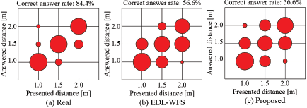
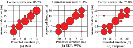
To confirm whether humans can perceive the sound image of the VSS constructed by the proposed method, we also carried out subjective evaluation experiments. The experimental conditions and equipment were almost the same as those shown in Tables 1 and 2. Six participants (three females and three males) were asked to sit at rref = [02.5]T, face the PLA, and keep their eyes closed. VSSs were constructed with 2 parameters: distance and direction. The distance was set to 1.0, 1.5, and 2.0 m, while the direction was set to 0, ±15, and ±30 deg. Then, 15 stimuli patterns were given in random order, and each pattern was given twice. The participants were required to answer the sound’s perceived distance and direction separately. Wideband white noise of 0–8 kHz was used as the sound source, which is the same as that used in the objective evaluation.
The results for the perceived distance and direction are shown in Figures 11 and 12, respectively. The proposed method reached the same level in distance perception and a lower level in direction perception compared to EDL-WFS. However, when we collected the correct answer rate for both the distance and direction, we obtained the results as Real: 76.6%; EDL-WFS: 47.0 %; Proposed: 50.6 %. Therefore, we confirmed that the proposed method reaches a precision similar to that of EDL-WFS in the perception of sound images.
4 Evaluation Experiments for Moving VSS Construction
Because our objective was to develop a movable VSS construction method, we also evaluated the perception when a moving VSS was constructed. We prepared six cases of VSS motion for the following experiments, as shown in Figure 13. Cases I, II, and III are motions along the x-axis, while cases IV, V, and VI are motions along the y-axis. In each case, the VSS was moved in a uniform rectilinear motion for 3.3 s, which produced N = 11 frames. The sound image localization when the VSS was moving along the x-axis was easy to evaluate because the direction to the observation position changes as the VSS moves. However, the localization is difficult to evaluate when the VSS was moving in the y-axis direction because the direction to the observation position remained unchanged as the VSS moved. Therefore, in the objective evaluation of sound image localization, we only evaluated cases I, II, and III. In the subjective evaluation of motion perception, we evaluated all six cases.
4.1 Objective Evaluation of Sound Image Localization
In this experiment, a binaural microphone (NEUMANN, KU-100) was set at the observation position in Figure 13, which is the same position as rref = [02.5]T in Section 3.2. The other experimental conditions and equipment are the same as those shown in Tables 1 and 2. The ILDs and IACCs for cases I, II, and III were calculated from the observed signals with the same procedures described in Section 3.2.
The ILD transitions are shown in Figure 14. The horizontal axis denotes the x-coordinate of the moving VSS, and the vertical axis shows the corresponding ILD result. It was confirmed that when x < 0, the VSS was constructed on the right hand of the observation position, resulting in a negative ILD value. It was also confirmed that the proposed method achieved a much more significant transition around x = 0 than Real and EDL-WFS did. This result can be explained by the sharp directivity of the PLA, and it implies that the proposed method may lead to a precise perception of the sound image. Moreover, it can be seen that when the VSS was constructed far from the observation position (x < −0.5 or x > 0.5), the proposed method shows a less significant ILD. This can also be explained by the sharp directivity of the PLA. When the VSS was constructed far from the observer, the parametric loudspeakers near the VSS position emitted more power; however, only a little power reached the observation position due to the sharp directivity of the PLA.
The IACC transitions are shown in Figure 15. The horizontal axis denotes the x-coordinate of the moving VSS, and the vertical axis shows the corresponding IACC result. It was confirmed that in cases I, II, and III, the proposed method achieved a much higher IACC value than the EDL-WFS case, which implies that the direction of the VSS constructed by the proposed method is more accurate than that of EDL-WFS. It can also be seen that when the VSS was constructed far from the observation position, the proposed method reached a higher IACC than did the Real case. However, when the VSS was constructed near the observation position, the proposed method achieved a lower IACC than Real did. This can be explained by the fact that in the Real method for Case III, the direct sound is much louder than the indirect sound because the loudspeaker is set near the observation position. Although the parametric loudspeaker has a sharp directivity, the PLA was set 2.5 m away from the observation position, which leads to more indirect sound and a lower IACC. The ILD and IACC results demonstrate that the VSS moving along the x-axis constructed by the proposed method can be perceived.
4.2 Subjective Evaluation of Motion Perception
To confirm that humans can perceive the motion of the VSS constructed by the proposed method, we carried out additional subjective evaluation experiments on this aspect. The experimental conditions and equipment were almost the same as those shown in Tables 1 and 2. As in the experiment described in Section 3.3, three females and three males participated in this experiment. The participants were asked to identify the start position and end position of the VSS. The six stimulus patterns were given in random order, and each pattern was given twice. We defined the presented start position and end position as rp,s = [xp,syp,s]T and rp,E = [xp,Eyp,e]t, and defined the identified start position and end position as rO,S = [xO,SyO,S]T and rO,E = [xO,EyO,E]T, respectively. The error of the perceived distances moved along the x-axis and y-axis can be calculated as:
A smaller value suggests a higher precision in the perceived moving distance of the VSS. The error of the perceived positions along the x-axis and y-axis can be calculated as
A smaller value suggests a higher precision in the perceived position of the VSS.
The results for the errors of the perceived moving distance are shown in Figure 16, and the errors of the perceived position are shown in Figure 17. Figures 16(a) and Figure 17(a) confirm that the proposed method achieved a precision higher than that of EDL-WFS and Real in both the perceived moving distance and the perceived position when constructing a VSS moving along the x-axis. In contrast, Figures 16(b) and Figure 17(b) confirm that the proposed method achieved a precision lower than that of EDL-WFS and Real in both the perceived moving distance and the perceived position when constructing a VSS moving along the y-axis. These conclusions correspond to the conclusions of other experiments reported in this paper. Compared with EDL-WFS, the observed sound of the proposed method includes less indirect sound because of the sharp directivity of the PLA. Therefore, the VSS motion along the x-axis is easy to perceive, which leads to the high precision of the proposed method in the x-axis motion. The VSS is perceived near the observation position when it moves along the y-axis, which leads to the low precision of the proposed method in the y-axis motion. The evaluation results demonstrated that the proposed method can construct a moving VSS with higher precision in the x-axis but a lower precision in the y-axis compared with conventional EDL-WFS.
5 Conclusion
In this paper, we proposed a movable VSS construction method based on WFS using a linear PLA. In the proposed method, driving functions are designed based on the WFS theory to achieve the desired VSS position. During the construction of a moving VSS, the motion path is divided into several positions, and the processed signals are then integrated with crossfade processing. To demonstrate the effectiveness of the proposed method, we carried out objective evaluation experiments on the sound pressure distribution, ILD, and IACC. We also carried out subjective evaluation experiments on the sound image localization. The experimental results demonstrate that the proposed method is able to produce a stationary VSS or a moving VSS. Compared with conventional WFS using EDLs, the proposed method has lower precision when the VSS is moving vertically with respect to the loudspeaker array, but it has higher precision when the VSS is moving parallel to the loudspeaker array.
In the future, we will take the influence of the PLA’s sharp directivity into consideration when designing the driving functions. For example, we will consider the ratio of direct sound and indirect sound to improve the perception of a VSS. Because the proposed method is superior to the WFS using EDLs when the VSS moves parallel to the loudspeaker array, we will also consider combining parametric loudspeakers and EDLs to construct a VSS with higher precision in both the parallel and vertical directions.
This work was partly supported in part by Ritsumeikan Global Innovation Research Organization (R-GIRO), and by JSPS KAKENHI Grant Numbers JP19H04142, 21H03488, 21H04427 and 21K18372.