Reconfigurable Intelligent Surfaces (RISs) have emerged as a promising technology for enhancing wireless communication by reconfiguring the propagation environment. Most existing studies assume ideal RIS elements with zero electrical resistance, which limits their applicability in realistic settings. This study considers a practical RIS-aided wideband OFDM system with resistive reflecting elements (REs), where a single-antenna source communicates with a single-antenna destination. The goal is to maximize the transmission rate by jointly optimizing the subcarrier power allocation and RE phase shifts. An alternating optimization (AO) framework is proposed, in which each variable is updated iteratively, and the phase shifts are refined via gradient descent (GD). A joint optimization strategy was also considered for comparison. Furthermore, a low-complexity alternative based on solving a channel power maximization (CPM) problem is introduced to obtain suboptimal phase shifts. The numerical results show that the AO method achieves near-optimal performance with a significantly reduced computation time compared to the successive convex approximation (SCA). Although the GD-based CPM method incurs higher complexity than dimension-wise sinusoidal maximization (DSM), it yields superior rate performance and improved robustness against RE resistance variations, making it more suitable for practical RIS deployment.
1. Introduction
Telecommunication systems undergo a revolutionary cycle every ten years, where each new cycle introduces significant performance enhancements to accommodate the rapid growth of data transmission demand driven by the continuously increasing number of connected mobile devices (Shafi et al., 2017). The Internet of Things (IoT), a paradigm in which almost any device can be connected to the Internet, is one of the largest contributors to the increasing number of connected devices and has led to an explosive growth in demand for throughput per area (bps/Hz/km2) in recent years (Björnson et al., 2017). However, in addition to increasing the throughput per area, other key performance indicators (KPIs), such as latency, reliability, mobility and energy efficiency, also require further improvement (Andrews et al., 2014).
Many key enabling technologies (referred to as disruptive technologies) have been integrated into communication systems to address these challenges. Typically, these technologies aim to explore new bandwidths, use novel waveforms or enhanced signal-processing methods, or leverage intermediate devices to assist in signal delivery (Letaief et al., 2022). In the latter case, various intermediate devices have been implemented to aid in wireless data delivery, including relays, backscatter devices and reconfigurable intelligent surface (RIS) systems.
Reconfigurable intelligent surface (RIS), also known as intelligent reflecting surface (IRS), is a disruptive technology recognized as a key enabler in transforming the next generation of wireless communication systems (Liu et al., 2021). RIS is a novel paradigm in which wireless data transmission is improved not only through the enhanced design of the transmitter and receiver but also by manipulating the wireless environment itself (Liang et al., 2019). By doing so, RIS opens up the potential for further improving wireless communication throughput, which has stagnated in recent years owing to the limitation of focusing only on the transmitter and receiver sides.
RIS systems consist of multiple reflection elements (REs) that can alter their electric and magnetic fields, and hence, change the phase and magnitude of the incident signal. Unlike conventional intermediary devices such as relays, REs are meta-materials (Basar et al., 2019) and do not incorporate active electronic components for communication, such as operational amplifiers and oscillators. Thus, they are suitable candidates for meeting the emerging need for green communication (Huang et al., 2019). Furthermore, due to the absence of basic data transmission processes, such as modulation, detection, encoding and decoding, beamforming is conducted passively, which has the advantage of significantly reducing power consumption and hardware complexity (Wu and Zhang, 2019).
The literature contains many studies on RIS-assisted wireless communication systems with various system models, including single-input single-output (SISO), multiple-input single-output (MISO), and multiple-input multiple-output (MIMO). SISO communication systems implemented with the assistance of RIS have been widely investigated (Björnson et al., 2020; Ding et al., 2020; Ding and Vincent Poor, 2020; Hou et al., 2020; Lyu and Zhang, 2020; Makarfi et al., 2020; Zhang et al., 2020, 2019). Björnson et al. (2020) compared two systems in which the communication performance was enhanced by RIS or relay performing in the Decode-and-Forward (DF) model, respectively. Makarfi et al. (2020) analyzed the average capacity, BER, and outage probability in an RIS-enabled IoT network with fading channels. Ding et al. (2020) analyzed the performance of a SISO system wherein a source with nonorthogonal multiple access (NOMA) capabilities simultaneously served two users using RIS with either coherent phase shifting or random discrete phase shifting properties. Zhang et al. (2019) proposed a method for minimizing the outage probability in a SISO system with a line-of-sight (LoS) channel model from and to the RIS elements. Ding and Vincent Poor (2020) designed a beamforming approach for a SISO downlink system wherein multiple users were served simultaneously using NOMA. In the considered scenario, some users were assumed to have no direct link to the base station (BS) and were hence assisted by RIS. The outage probability under the proposed beamforming method was calculated for both single-user and multi-user cases. Hou et al. (2020) considered an RIS-aided downlink network in which the BS sent data to several users simultaneously using a single antenna. The reflection design, outage probability, ergodic rate and spectral and energy efficiencies of the network were comprehensively discussed for the case in which the transmissions were handled using a NOMA scheme. Lyu and Zhang (2020) analyzed the achievable rate and spatial throughput of a network in which a BS served multiple users, each of which used an orthogonal resource block. Zhang et al. (2020) investigated the impact of the phase shift resolution on the performance of a RIS-assisted network with limited RIS phase shifts.
MISO communication systems using RIS to boost the system performance have been widely investigated (Guo et al., 2020; Kundu and McKay, 2021; Ma et al., 2020; Papazafeiropoulos et al., 2022; Wu and Zhang, 2019; Zhang and Zhao, 2021; Zhou et al., 2020). Wu and Zhang (2019) considered the problem of minimizing the total transmit power at the access point of an RIS-enabled MISO broadcast channel subject to satisfying quality of service (QoS) constraints. Separate optimization problems were formulated for both single-user and multiuser cases. Ma et al. (2020) considered a MISO single-user channel wherein the RIS not only assisted the BS data transmissions but also transmitted secondary additional data to the receiver. A method was proposed for determining the transmit precoder and reflection coefficient such that the transmit power at the BS was minimized while simultaneously ensuring the QoS of the primary data transmission. Kundu and McKay (2021) performed channel estimation for a RIS-enhanced MISO system serving a single user. The MMSE channel estimates obtained from several deep-learning approaches were compared with those obtained using conventional linear estimators. Guo et al. (2020) proposed a novel, low-complexity method for maximizing the sum rate of a MISO broadcast system with RIS. The analysis considered not only the case where the channel state information (CSI) was accurately known but also that in which the CSI was imperfect, resulting in the need for probabilistic optimization. Zhang and Zhao (2021) used the block minorization-maximization (BMM) method to obtain the transmit precoder at the BS and phase shift at the RIS that collectively maximized the sum rate of a MISO downlink system with the help of RIS. Zhou et al. (2020) minimized the total transmit power at the BS in a MISO system by optimizing the transmit precoder and RIS phase shift coefficient subject to QoS constraints for each user. A robust beamforming design was formulated to deal with the assumption of imperfect CSI, and a novel convex-concave procedure (CCP) was proposed to find a stationary solution for all possible channel-error realizations. Papazafeiropoulos et al. (2022) considered the problem of channel estimation and sum rate maximization in MISO networks with hardware impairments.
MIMO wireless systems with RIS have also attracted attention (Ning et al., 2020; Perović et al., 2021; You et al., 2021). Perović et al. (2021) maximized the achievable rate of a MIMO single-point RIS-assisted system by jointly optimizing the precoder at the transmitter and the reflection coefficient at the RIS using the projected gradient method to tackle the unit circle constraint. Ning et al. (2020) proposed a new metric called sum-path-gain maximization (SPGM) as an alternative to the conventional sum-rate maximization metric to find the optimal reflection coefficient of the RIS in a single-point MIMO system. You et al. (2021) aimed to find the optimal transmit precoders for each user and the RIS reflection coefficient that maximized the global energy efficiency in a multi-user MIMO system in which several users with multiple antennas simultaneously transmitted their uplink signals to a base station with the assistance of RIS.
All of the aforementioned studies assume that the reflection magnitude in the RIS system is constant. However, in real-world RIS systems, the magnitude of the reflection varies with the phase shift. Therefore, a growing number of researchers have recently adopted more realistic RIS reflection models (Abeywickrama et al., 2020; Cai et al., 2020; Cai et al., 2022; Li et al., 2021; Sun et al., 2023; Wang et al., 2021; Zhang and Li, 2022). Abeywickrama et al. (2020) applied a phase-shift-dependent magnitude reflection method to design an accurate beamforming approach for narrowband RIS-aided communications systems. Following (Abeywickrama et al., 2020), the authors in (Cai et al., 2020; Li et al., 2021) designed a more general framework for a practical reflection model that could be applied to wideband systems. The authors in (Sirojuddin et al., 2024; Sun et al., 2023; Wang et al., 2021; Zhang and Li, 2022) analyzed various aspects of RIS-assisted narrowband systems using the phase shift-dependent magnitude reflection model proposed in (Abeywickrama et al., 2020). Finally, the authors in (Cai et al., 2022) applied the practical reflection model presented in (Li et al., 2021) to an RIS-assisted multicell wideband system.
1.1 Contributions
The present study is essentially a combination of the two works presented in (Yang et al., 2020) and (Abeywickrama et al., 2020). In particular, the study considers a SISO OFDM communication system, in which the achievable rate is improved by enhancing the signal transmissions using RIS. However, in contrast to the ideal RIS model considered in (Yang et al., 2020), the present work uses the more practical model proposed in (Abeywickrama et al., 2020), in which the reflection magnitude of each reflecting element (RE) varies with the phase shift. The main contributions of this study are as follows:
The study considers the problem of maximizing the achievable rate in the considered OFDM system. This is achieved by maximizing the sum rate of each subcarrier by optimizing the power allocation on each subcarrier and the phase shift of each RE in the practical RIS model.
An alternating optimization (AO) method is proposed in which the considered problem is solved by optimizing the power allocation and phase shifts of the REs in turn. For each RE, the optimal phase shifts are obtained using the gradient descent (GD) method, in which the first differentiation of the achievable rate with respect to the phase shift is analytically derived.
The AO algorithm generally leads to a sub-optimal solution. Thus, to corroborate the optimality of the AO approach, a joint optimization method is proposed, wherein the power allocation and phase shifts are optimized at the same time with the assistance of the GD method once again.
As a lower-complexity alternative to the achievable rate maximization problem, the study also considers a channel power maximization (CPM) problem, in which the aim is to determine the sub-optimal phase shift of the RE. The sub-optimal solution obtained for the RE phase shift is then considered as the initial point for the main rate maximization problem.
The convergence rate of the GD method used in the two optimization procedures is heavily dependent on the step size. Accordingly, a simple method is proposed for managing the step size in such a way as to ensure the convergence of the GD method without significantly degrading the quality of the optimization results.
1.2 Notations
z, and denote scalar, vector, and matrix, respectively. For each matrix, the subscript denotes the entry of in row m column n. Notations , , , , and denote the transpose, complex conjugate, conjugate transpose, absolute value and matrix norm operators, respectively. Symbols and represent real and complex matrices, respectively, with size , while denotes the positive definite matrix. indicates a complex Gaussian random variable with zero-mean and covariance matrix . Finally, * denotes convolution.
2. System model
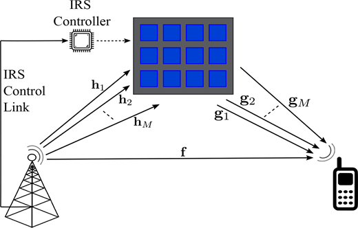
This study considers an OFDM communication system in which a single-antenna source (S) transmits a signal to a destination (D) with the assistance of a RIS system with M reflecting elements (REs), as illustrated in Figure 1. Assume that the OFDM system comprises N orthogonal subcarriers (SCs) that equally divide the whole bandwidth. Let , where , denotes the SC transmit power. Suppose the total power at S is . The total power allocation to the SCs must therefore satisfy .
Let denote the U-tap zero-padded discrete-time baseband-equivalent multipath channel for the S-D direct link. The S-D link through the RIS can be modeled as a concatenation of the S-RIS link and the RIS-D link for the OFDM wideband channel. Specifically, let and , denote the -tap baseband equivalent multipath channel from S to the RE and the -tap multipath channel from the RE to D, respectively. Each RE reflects the incident signal, resulting in not only a phase shift but also an amplitude attenuation. Let be a column vector containing all the reflection coefficients of the RIS, where is the reflection coefficient of the RE with magnitude and phase shift . The S-D link through the RE is then given by the concatenation of the S-RE link, RE reflection coefficient, and RE-D link. That is, , where . For ease of derivation, let the following notations be introduced:
i.e., , are the zero-padded concatenated S-RIS and RIS-D channels through the RE. The superposed channel impulse response (CIR) of S-D channel is the composite of the S-D (direct) channel and the S- RE-D channel, which is given by:
where . Let be the discrete Fourier transform matrix. The channel frequency response (CFR) of the superposed S-D CIR channel, denoted as , is then expressed as , while the CFR at each SC is expressed as:
where is the column of . Assume that the OFDM symbol contains a cyclic prefix of length . The achievable rate of the considered OFDM system is thus expressed as (Yang et al., 2020):
where is a coefficient representing the shortfall between the maximum theoretical channel capacity and the actual capacity achieved using a practical modulation and coding scheme (MCS). In addition, is the noise power at each SC.
This study considers a practical RIS model wherein the reflection amplitude from each RE varies with its phase shift. In practical RIS systems, the REs have an electronic circuit arrangement in which a variable capacitor can be adjusted in such a way as to yield the desired phase shift of the incident signal, as shown in [1, Figure 2]. Based on the figure, the phase shift of the REs is given in (Abeywickrama et al., 2020; Cai et al., 2020) as:
where is the impedance of the RE whose value is controlled by adjusting the capacitor capacitance , given by:
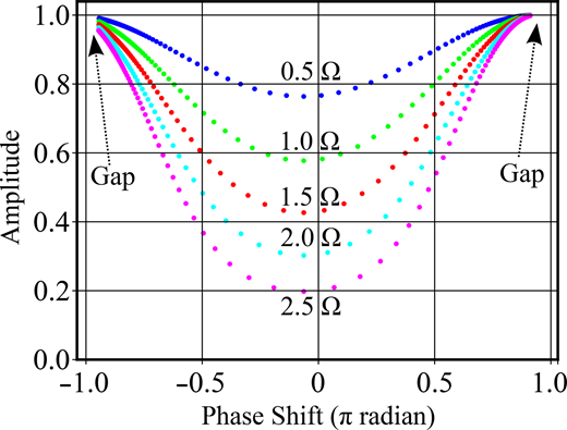
where the constants , , R, and are the inductances of inductors 1 and 2, the resistance of the RE resistor, and the frequency of the incident signal in rad/s, respectively. Note that affects not only the value of the phase shift reflection , but also the amplitude of the reflection . Given a set of values of ranging from to , equation (5) outputs a set of values of in which , , R, and are taken as constants. After obtaining these values, a set of paired values of and can be extracted. Plotting versus yields a distorted U-shaped curve depicting the relationship between and , as shown in Figure 2. As described in (Abeywickrama et al., 2020), the relationship between and can be accurately approached using the equation:
where the parameters , , and k are obtained using the regression technique, and and are obtained when and , respectively. Note that the parameters in (2) reflect the inherent characteristics of each RE in the RIS system and are independent of the channel statistics. In other words, their values are determined in a one-off procedure prior to RIS installation and are then applied in future practical implementations without any further consideration.
3. Problem formulation and proposed algorithms
This study aims to determine the phase shift vector and power allocation matrix over N subcarriers such that the sum rate over all the subcarriers is maximized. This problem can be mathematically formulated as follows:
Remark 1: For clarity of exposition and to isolate the impact of the practical RIS model, this work focuses on a SISO OFDM system, which is representative of low-complexity and energy-constrained scenarios such as IoT and edge devices, as reflected in (8). The formulation can be extended to MISO or MIMO systems by replacing the scalar effective channel term with its vector- or matrix-valued counterpart that incorporates transmit beamforming and/or receive combining. In such extensions, conventional beamforming strategies, such as maximum ratio transmission (MRT) for MISO systems and singular value decomposition (SVD)–based precoding for MIMO systems, can be naturally incorporated. Correspondingly, the diagonal power allocation matrix would be generalized to a transmit covariance matrix, leading to a log-determinant rate expression. Although these extensions increase the problem dimensionality, the joint optimization structure and the alternating optimization with gradient-based updates developed in this work remain applicable, albeit with higher computational complexity.
3.1 Achievable rate maximization using alternating optimization
Because the joint optimization (8) over and is challenging, this study proposes an alternating optimization (AO) algorithm (Abeywickrama et al., 2020) which optimizes each target alternately. Given , problem (8) reduces to:
where is a constant w.r.t. . The convex problem (9) is solved by using the KKT conditions, where the solution is given by:
where is a constant set to meet the sum power constraint . The value of can be found using the water-filling (WF) algorithm or using the Newton-Raphson Method proposed in (Sirojuddin et al., 2024).
Given , problem (8) can be recast as:
Note that by substituting the constraint (11 b) into the objective (11a), and always keeping between and (by executing (29)), problem (11) becomes an unconstrained maximization problem where the optimal value can be found using the gradient descent (GD) method. In particular, the optimal can be obtained by iteratively executing the following equation:
where is the step size, and i is the iteration index.
To obtain the value of vector , it is first necessary to analytically determine the value of its elements, which can be expressed using the chain rule as follows:
where , and are defined as:
The second equality in (13) holds because , and , are real. Based on (13), the next task is to analytically derive the values of and .
It follows simply from (14) that:
The problem of determining can be broken down into that of computing the values of and , respectively. The value of is given by:
where from (18), each component of can be obtained as:
Because , the value of is expressed as:
where, from (2), it can be verified that:
From (19) and (20), the value of can be calculated as:
Given (17) and (22), (13) can be calculated. However, the calculation process involves a loop computation over N subcarriers. Furthermore, (13) needs to be repeated M times to yield the derivation of . This serial computation spends a lot of time, and hence, a kind of parallel computation needs to be structured as a substitution. To facilitate parallel computation, it is necessary to construct a compact form of that is structured from matrix multiplication. To achieve this, let the following vector be defined: . Furthermore, let us introduce a Jacobian matrix , whose entry in row n column m is the first derivative of w.r.t. , i.e.. The value of can then be generalized from (13) for all as follows:
i.e. the first derivative of over all s, i.e., is a (column) vector whose entry is the sum of all elements in column m of divided by .
The analytical expression of can be determined by breaking it down into the product of two Jacobian matrices. Because , the Jacobian of can be expressed as:
where , and is given by:
i.e. is a Jacobian matrix in which the entry in row n column n is given by (17). Note that is diagonal because for all .
Next, the analytical expression of the Jacobian matrix must be calculated. Through an appropriate matrix structure manipulation, (3.1) can be restructured as:
where is given by:
i.e. is a Jacobian matrix whose entry in row m column m is given by (20). Note that is diagonal because for all . From (26), the Jacobian matrix is then expressed as:
At this point, (25) and (28) have both been analytically calculated. Therefore, in (24) can be easily obtained, and in (23) is ready to be implemented in (12) to seek an optimal solution for by using the GD method.
Algorithm 1 presents the pseudo-code of the proposed AO algorithm, where denotes the convergence threshold and represents the maximum number of iterations. As shown, the algorithm alternately optimizes using the WF algorithm (line 4) and using the GD algorithm (lines 6–10). Because is bounded by and , line 9 updates using the following equation:
i.e. if , then is set to ; if , then is set to ; otherwise, is kept as it is.
Algorithm 1.AO procedure for solving problem (8)
3.2 Achievable rate maximization using joint optimization
Because an AO algorithm separates the joint variables and attempts to optimize each variable in turn, it may require many iterations to converge (Perović et al., 2021). Thus, the AO algorithm proposed in Subsection 3.1 might require a long computational time. In addition, the optimality of its solutions is not guaranteed to be better than that of a joint optimization algorithm. Accordingly, this section proposes an alternative approach, in which problem (8) is solved by optimizing and jointly rather than separately. The purpose of this alternative method is to assess the optimality of the main proposed AO algorithm and to evaluate its computational time.
As stated in Subsec. 3.1, the problem of solving given (problem (9)) can be tackled using the iterative water-filling (WF) algorithm, which is a simple algorithm with linear complexity (Khakurel et al., 2014). Accordingly, this section commences by defining an open-form function that takes as an input (along with other constants such as the channel, transmit, and noise powers), computes the optimal power allocation , and then outputs the rate.
Definition 1. Function is an open-form function comprising three steps. In particular, it 1) takes as one of its inputs, 2) calculates the power allocation given using the WF algorithm, and 3) outputs the rate using (4).
As explained in Definition 1, is open form because it uses the iterative, linear complexity WF algorithm to calculate the optimal . Note that takes only as its input, and is hence different from (4), which takes both and as inputs. In other words, function has only one independent variable, , and thus the main problem (8) takes the following form:
By substituting the equality constraint (30 b) into the objective (30a) (and always keeping between and , similar to the case described in Subsec. 3.1), problem (30) becomes an unconstrained maximization problem, for which the optimal solution can be determined using a conventional method such as GD. In particular, is iteratively updated using the following equation:
where is the step size. Because is not a closed-form function (owing to the iterative WF algorithm), cannot be found analytically. Nevertheless, its value can be approximated using the following limit equation approach:
Due to the round-off error in digital machines, the value of cannot be set too low in practical applications. As a result, the value of obtained when (32) is implemented in an algorithm is approximate rather than exact. Nonetheless, a tiny value of approximately is typically sufficient to closely approximate the true derivative value. In addition, the approximation error of (32) is proportional to (Chapra and Canale, 2015). The overall procedure for obtaining the optimal value of using the GD algorithm is shown in Algorithm 2, where denotes the convergence threshold and represents the maximum number of iterations.
Algorithm 2. Joint procedure for solving problem (30)
3.3 Reconfigurable intelligent surfaces phase-shift initialization based on channel power maximization
Alg. 1 requires an initial RIS phase-shift vector as a starting point for the iterative optimization. The quality of this initial phase-shift configuration has a significant impact on the convergence behavior and performance of the algorithm. To this end, following (Yang et al., 2020), this study uses the channel power maximization (CPM) problem as a low-complexity approach to obtain an effective initial estimate of .
The underlying idea of CPM can be explained as follows. Referring to the system model in Figure 1, increasing the number of reflecting elements (REs) at the RIS creates multiple propagation paths between the source and destination. By appropriately adjusting the RIS phase shifts, the reflected signals can be constructively combined at the receiver, resulting in a higher effective channel power, denoted by . As discussed in (Yang et al., 2020), a larger effective channel power generally provides favorable conditions for achieving a higher achievable rate. More rigorously, Proposition 1 in (Ning et al., 2020) shows that, under equal power allocation, maximizing the effective channel power corresponds to maximizing a lower bound of the achievable rate. In this sense, CPM can be viewed as a computationally efficient surrogate objective for RIS phase-shift initialization.
Motivated by both this physical intuition and the aforementioned theoretical insight, CPM is formulated to maximize with respect to the RIS phase shifts, as given by:
Similar to problem (8), problem (33) can be rendered essentially unconstrained by substituting constraint (33b) into objective (33a). Problem (8) can then be solved by using the GD method once again. In particular, the sub-optimal value of can be obtained by iteratively executing the following equation:
where is the step size.
To determine the value of , let us first analytically find the values of its elements, which, by using the chain rule, can be expressed as:
The derivation of has already been given in (20). The value of is expressed as:
Substituting (20) and (36) into (35) yields:
From (37), the vector form of is expressed as:
where is given by (27). With the analytical expression of given by (38), can be updated using the GD method stated in (34). Algorithm 3 presents the pseudo-code of the CPM-based phase-shift initialization, where denotes the convergence threshold and represents the maximum number of iterations.
Algorithm 3. Procedure for finding sub-optimal θ using CPM metric
It is worth noting that CPM is not intended as an alternative to the rate maximization problem, because the CPM objective is independent of the power allocation matrix . Consequently, the resulting phase-shift solution depends only on . Compared with the rate maximization problem, CPM involves fewer optimization variables and simpler operations, leading to substantially lower computational complexity. The obtained phase-shift vector is then used to initialize Algs. 1 and 2, where joint optimization of and is subsequently performed.
3.4 Step size control and complexity analysis
The GD method is used several times in the previous sections, including in (12), (31) and (34). One of the most critical parameters in the GD method is the step size, which directly impacts the convergence rate. Thus, in the present study, a simple mechanism is incorporated into the GD method used in Algorithms 1, 2 and 3 to improve its convergence. Let the update equations be denoted as , where represents , and , and s represents , and in (12), (31) and (34), respectively. Notably, the value of is not determined at the beginning of Algorithms 1, 2, and 3, but in the first iteration (). In particular, after calculating , is determined as:
i.e. is divided by the largest entry of vector . In other words, at , the largest step taken to translate to is limited to , i.e.. By leveraging the fact that the phase shift is bounded by and , the value of can be intuitively chosen as a particular positive number, for example, between 0 and .
Besides initializing , it is also necessary to monitor the monotonicity of the iterations. In the present study, this property is addressed using the simple step-size control mechanism proposed in (Sirojuddin and Huang, 2022). Suppose the value of s at the th iteration, i.e. , has been calculated. At the th iteration, after calculating and updating , the value of is computed and compared with . If the value of is negative (indicating that the step size is too large), is reduced by , where . is then re-updated and is re-evaluated. This loop terminates once is non-negative. This simple procedure ensures the monotonicity of s over the iterations with minimal computational cost.
In practice, the computational complexities of Algs. 1, 2 and 3 must be analyzed to properly understand the effects of increasing the values of M, N, and the other size-representing variables on the growth of the required computational resources (e.g. time or memory). In Alg. 1, the computational complexities of lines 1, 4, 7, 8 and 9 are , (Khakurel et al., 2014), , and , respectively. Because evaluating the objective function (4) as a termination criterion has a complexity of , the overall complexity of Alg. 1 after incorporating the step-size control mechanism is given as: , where , , and are the values of at the end of Alg. 1, the average value of in each , and the average iteration number of the step-size control mechanism, respectively.
In Alg. 2, the computational complexity of line 4 is , where the factor 2 M comes from repeating the calculation of 2 M times in (32). Consequently, the overall complexity of Alg. 2 after incorporating the step-size control strategy is equal to: , where and are the value of i at the end of Alg. 2 and the average iteration number of the step-size control strategy, respectively.
In Alg. 3, the computational complexity of line 4 is . Because the evaluation of the objective function (33a) as a termination criterion has a complexity of , the overall complexity of Alg. 3 is , where and are the value of i at the end of Alg. 3 and the average iteration number of the step-size control mechanism, respectively.
4. Simulation results
This section presents the evaluation results obtained using the proposed algorithms when applied to the considered OFDM system with a realistic RIS model. Unless otherwise specified, the simulation settings are as follows. For the practical RIS model described in (5) and (6), nH, nH, GHz, and as per (Zhu et al., 2013). Regarding the wideband channel and OFDM modulation scheme, , , , and dB (Yang et al., 2020).
The small-scale fading modeling for the wideband channel , and , is detailed as follows. Because the LoS path of the S-D link is typically blocked, all non-zero elements of are modeled as mutually independent complex Gaussian random variables. On the other hand, because the RIS is typically located such that the S-RIS and RIS-D links contain LoS paths in the first tap CIR, the first elements of and , i.e. and , respectively, are modeled as Rician fading, which is given by:
where is the Rician factor of z, with being the LoS component with a value determined by the angle of departure and arrival (Ning et al., 2020), and is the non-LoS (NLoS) component, which is modeled as a complex Gaussian random distribution . The remaining CIR taps of and contain no LoS components and are therefore modeled as zero-mean complex Gaussian random variables.
The large-scale fading of the channels is described as follows. The first CIR tap power of , , and is represented in (Du et al., 2022) as:
where and are the reference distance and path loss at , respectively, and is the path loss exponent. Given the first CIR tap power expressed in (41), the uth channel tap power, , can be obtained in (Dixit and Katiyar, 2016) as:
where is the power decay factor. In this study, the simulation settings for the wideband channel are as follows: dB and distance d values for , , and , of 50, 30 and 40 m, respectively. In addition, the path loss at the reference distance m is set as −30 dB (Shi et al., 2022), and the path loss exponent for the direct link is 3. Finally, the path loss exponents for the through-RIS links and , are set equal to 2 (Miranda et al., 2013).
As stated in the previous section, this study considers a practical RIS model. In other words, the proposed algorithms take into account the resistance R of the REs during the optimization process. All of the algorithms (1, 2 and 3) are general frameworks that can be equally applied to an ideal RIS system with as well. The following results and figures demonstrate the importance of considering the practical RIS model rather than the ideal one by providing benchmark methods that regard the RIS as ideal, even though most RIS systems have positive (i.e. non-zero) values of R.
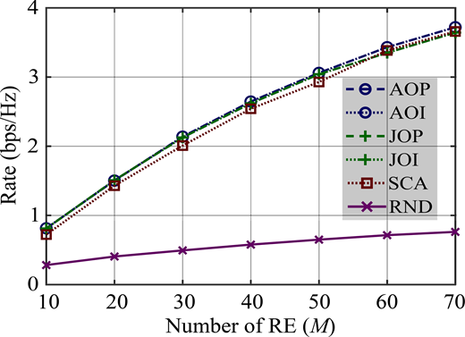
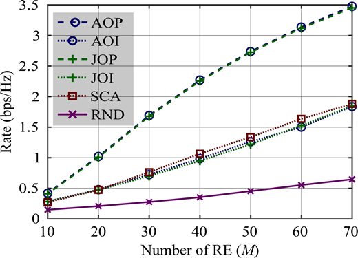
Figures 3–8 below compare the results obtained from six methods that can all be used to solve problem (8). The legends in the six figures are defined as follows:
AOP (standing for the Alternating Optimization, Practical) is the main optimization method proposed in this study (Algorithm 1) and is based on an alternating optimization strategy. The method considers the REs within the RIS system to have resistive properties, R.
AOI (standing for the Alternating Optimization, Ideal) is similar to the main proposed method but operates under the assumption that the RIS is ideal , even though deployed RIS systems actually have non-zero values of R. Based on the ideal RIS assumption, Alg. 1 is executed, and the obtained optimal phase shift is then used to calculate (4) using the true value of R.
JOP (standing for the Joint Optimization, Practical) is the supplemental method (Algorithm 2) based on a joint optimization concept. The method is intended to verify the optimality of the main AO strategy and considers the true values of the RE resistance, R.
JOI (standing for the Joint Optimization, Ideal) is the same as Algorithm 2 but assumes the RIS to be ideal . Based on the ideal RIS assumption, Alg. 2 is executed, and the obtained optimal phase shift is then used to calculate (4) using the true value of R.
SCA is the successive convex approximation algorithm proposed in (Yang et al., 2020). In particular, this method transforms the rate maximization problem (11) into an alternative convex problem, and then iteratively uses a convex tool to solve the transformed problem. The solution procedure assumes the RIS model to be ideal.
RND is a random phase-shift-based solution.
Note that in what follows, the method denoted as AO refers to both AOP and AOI. Similarly, JO refers to both JOP and JOI.
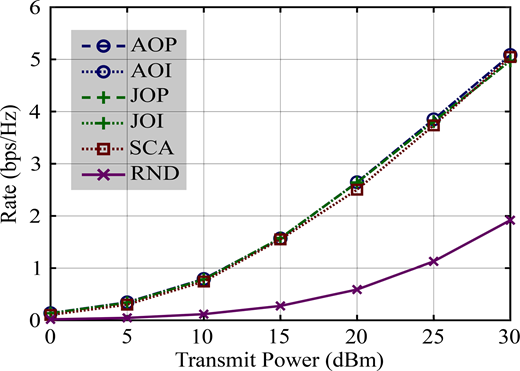
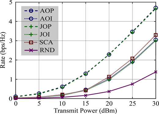
Figures 3 and 4 show the achievable rate versus transmit power for the six considered methods. Figure 3 considers the case of an ideal RIS with , while Figure 4 shows a practical RIS with . As seen in Figure 3, the AO, JO, and SCA methods significantly outperform RND, indicating the importance of using an optimization method to design an appropriate RIS phase shift. Interestingly, the results obtained using AO and JO coincide. In other words, the performance of the alternating optimization framework (Alg. 1) in solving problem (8) is comparable to that of the joint optimization framework (Alg. 2). In addition, the SCA method shows only a minor performance gap compared to the AO and JO methods. The rate results obtained from AOP coincide perfectly with those of AOI, while those obtained from JOP align exactly with those of JOI because the REs in the RIS have zero resistance. In Figure 4, however, in which the REs have a resistance value of , AOP and JOP significantly outperform AOI, JOI and SCA, thereby confirming the importance of incorporating the RE resistance value into the optimization problem. The rates obtained from AOP and JOP in Figure 4 are very similar, just as in Figure 3 for . Thus, the results once again show that the performance of the alternating-based optimization method is comparable to that of the joint optimization method.
Figures 5 and 6 show the achievable rate versus the number of REs in the RIS (M) for the six methods under consideration. Figure 5 again shows the case of an ideal RIS with , while Figure 6 shows a practical RIS with a resistance of . The findings in Figure 5 are similar to those in Figure 3. In particular, methods AO, JO and SCA significantly outperform RND, while methods JO and AO yield very similar rates. In addition, the rate performances of AO and JO are similar to that of the SCA benchmark. In other words, the relative performance of the considered methods remains unchanged in the ideal RIS model as the number of REs increases. In Figure 5, the rate performances of the models based on a practical RIS assumption (AOP and JOP) are consistent with those obtained from the methods based on an ideal RIS model (AOI, JOI, and SCA). However, in Figure 6, for a practical RIS with , AOP and JOP significantly outperform the latter models. This finding again confirms the importance of considering the RE resistance value R when determining the optimal values of the power allocation and phase shift for practical RIS models.
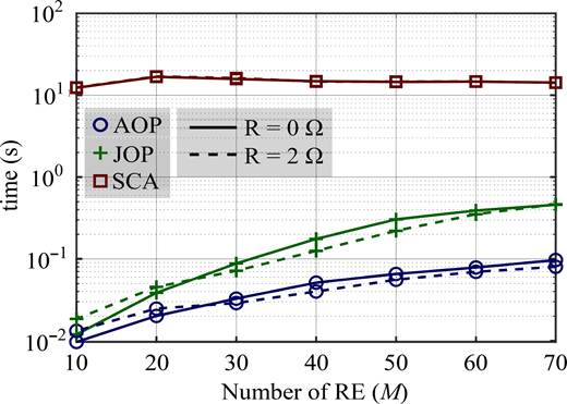
Overall, the results presented in Figures 4 and 6 show that the two algorithms proposed in the present study, namely, AOP and JOP, provide a better performance in designing the RIS phase shifts than the SCA method proposed in (Yang et al., 2020), particularly in practical RIS systems containing REs with resistance. For the case of an ideal RIS model, AOP and JOP achieve a rate performance similar to that of SCA, which implies that the importance of these methods relative to that of SCA diminishes in an ideal RIS system. However, to explore this issue furthermore, Figure 7 compares the average computational times of the three methods as a function of the number of REs in an ideal RIS system and a practical RIS system, respectively. The proposed AOP and JOP algorithms exhibit considerably lower computational times than the SCA method for both RIS models. For instance, when , the computational time ratio between AOP and SCA is approximately 1000. For SCA, the computational time remains high for all values of M because it iteratively implements a general convex solver to find a stationary point. By contrast, the computational times of AOP and JOP increase with M for low values of M, but then stabilize as M continues to increase. Overall, the results shown in Figure 7 indicate that the alternating optimization (AO) strategy is the most computationally efficient method for solving the main optimization problem considered in the present study. Notably, the computational time is unaffected by the resistance value (i.e. , or ).
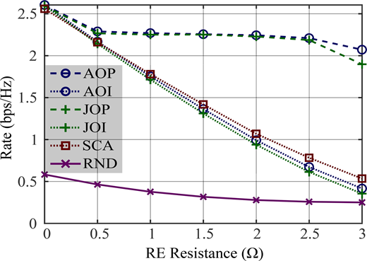
To highlight the importance of considering the RE resistance when dealing with a practical RIS, Figure 8 shows the variation of the achievable rate with the RE resistance for each of the six methods under consideration. All of the methods (with the exception of the RND method) perform equally well when . The practical RIS-based methods (AOP and JOP), which consider the RE resistance value when determining the optimal RIS phase shift, exhibit a relatively stable performance as the RE resistance increases. However, for all of the models based on an ideal RIS assumption (AOI, JOI and SCA), the rate decreases significantly as the RE resistance increases. It is an additional note that, at relatively large RE resistance values, a slight performance gap between AOP and JOP can be observed, which is mainly attributed to the increased numerical sensitivity of the gradient approximation (32) under severe channel attenuation and power allocation variations.
In addition to addressing the rate maximization problem, the present study also considers the sub-optimal criterion of channel power maximization (CPM), as stated in problem (33) and solved using Alg. 3. The performance of Alg. 3 is evaluated via a comparison with three benchmarks whose legends are described in the following:
GD: the proposed method (Alg. 3), which considers a practical RIS model.
DSM: the dimension-wise sinusoidal maximization method introduced in (Sirojuddin et al., 2022). DSM can be used to solve problem (33) under the assumption of an ideal RIS model.
SDR: the semidefinite relaxation technique followed by Gaussian randomization proposed in (Yang et al., 2020). Similar to DSM, the SDR method assumes that the RIS system is ideal.
RND: the phase shift solutions required to solve problem (33) are determined randomly.
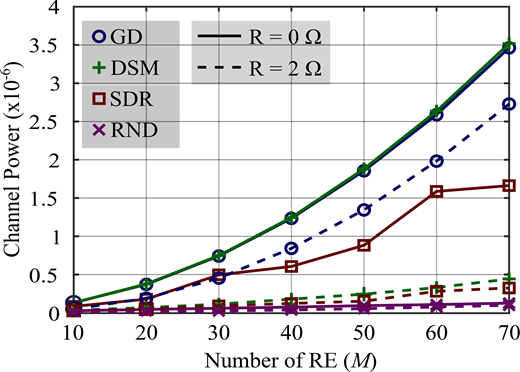
Figure 9 shows the relationship between the channel power and the number of REs (M) for each of the four methods. In the ideal RIS scenario, the GD and DSM methods exhibit similar performances, as discussed extensively in (Sirojuddin et al., 2022). The SDR method achieves a lower channel power than GD and DSM because it uses an indirect optimization approach followed by a matrix rank relaxation procedure. Moreover, the solution obtained after performing semi-definite programming (SDP) with rank relaxation is not directly applicable because it requires a further Gaussian randomization step, which leads to nonstationarity in the optimal solution. The RND method achieves a low channel power for both and , which highlights the need for an algorithm to determine the optimal phase shift when solving problem (33). In the practical RIS scenario, the proposed GD method outperforms all three benchmarking methods (DSM, SDR and RND). This finding emphasizes the importance of considering the resistance properties of the REs when designing the sub-optimal phase shift for problem (33). Notably, when dealing with the practical RIS model, DSM, SDR and RND, which are all based on an ideal RIS assumption, exhibit negligible performance differences.
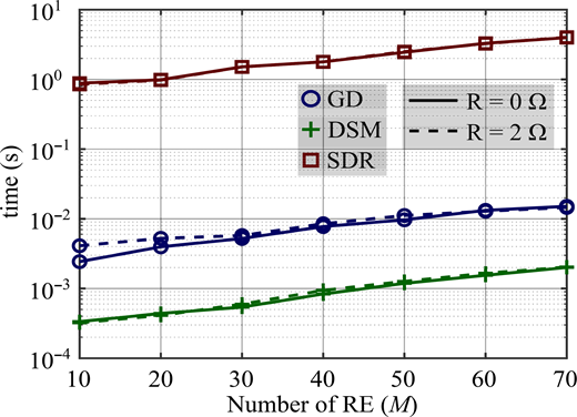
Figure 10 shows the correlation between the execution time and the number of REs (M) for the GD, DSM and SDR methods. DSM achieves the lowest execution time of the three methods in both RIS scenarios. The execution time of GD is approximately ten times longer than that of DSM. Moreover, SDR has the longest execution time of the three methods, surpassing GD by more than 100 times and DSM by almost 1,000 times. Figures 9 and 10 imply that DSM is the most favorable option under the ideal RIS scenario. However, in the practical RIS case, GD significantly outperforms the other methods, including DSM, and is thus the preferred option, particularly when the optimality of the power allocation and phase shift results is more important than the execution time. In addition, the execution times of all methods under consideration in Figure 10 are independent of the RE resistance value.
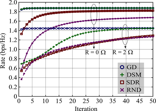
Figure 11 illustrates the convergence behavior of Alg. 1 under different initial RIS phase-shift configurations obtained from various solutions of the CPM problem. Specifically, the GD-, DSM-, SDR- and random-based methods are used to generate the initial phase-shift vector , which is then provided to Alg. 1 for joint optimization of the RIS phase shifts and the power allocation matrix. In the ideal RIS scenario, both the GD-based and DSM-based initializations lead to fast convergence, with Alg. 1 converging in fewer than five iterations. This observation is consistent with the fact that DSM was originally developed for ideal RIS configurations and performs effectively under such conditions. However, when the RIS is defective (e.g. ), the GD-based solution of the CPM problem provides a higher-quality initial point than DSM, allowing Alg. 1 to still converge within fewer than five iterations. By contrast, in this case, DSM requires approximately 40 iterations to reach convergence. These results indicate that solving the CPM problem via the proposed GD method yields a robust and computationally efficient initializer for Alg. 1 across both ideal and defective RIS scenarios. In addition, the initializations obtained from SDR and random methods lead to slower convergence and inferior final performance. Notably, the subsequent AO iterations in Algorithm 1 remain necessary to refine the solution further and achieve higher achievable rates through joint optimization of the RIS phase shifts and power allocation. This comparison highlights the practical trade-off between initialization quality and iterative refinement, and justifies the inclusion of the full AO stage following the CPM-based initialization.
5. Conclusion
This study has considered an OFDM communication system wherein a single-antenna source transmits data to a single-antenna destination through a wideband channel with the assistance of a practical RIS system with reflection element (RE) resistance. An alternating optimization (AO) strategy has been proposed to solve the formulated rate maximization problem, where the optimal power allocation is acquired using the water-filling algorithm and the optimal phase shift is derived using the gradient descent (GD) method. For comparison purposes, a supplementary method has been presented that solves the two variables of interest jointly rather than separately to validate the optimality of the AO strategy. Finally, a channel power maximization (CPM) problem with lower complexity has been formulated to derive the sub-optimal phase shift for the OFDM system. The convergence of the GD method has been improved through two strategies aimed at determining the initial step-size value and then adjusting the step-size value as the optimization process proceeds. A complexity analysis has been performed for all the proposed algorithms. The numerical results have shown that the proposed AO strategy achieves a rate performance similar to that of the joint-optimization framework. Moreover, both strategies outperform the considered benchmark methods, particularly in practical RIS systems with RE resistance. Among all the considered methods, the AO method yields the shortest computation time. In general, the results have confirmed the importance of considering the RE resistance when designing the optimal power allocation and RE phase shifts in a RIS-enabled OFDM system. This study assumes perfect channel state information for all links, which is a standard modeling choice to facilitate algorithm design and performance benchmarking. While channel estimation errors may degrade the achievable rate in practice, the proposed framework is expected to preserve its main performance trends under moderate CSI inaccuracies, which remains an interesting direction for future investigation. This work focuses on achievable rate as the primary performance metric, because it directly reflects the physical-layer benefits of joint power allocation and RIS phase-shift optimization and remains independent of specific modulation, coding, and receiver designs. Other metrics, such as bit error rate or outage probability, are closely related to the achievable rate through the effective received SNR under fixed transmission settings, but their explicit evaluation would require additional system assumptions and is therefore left for future investigation. In addition, the proposed GD method for solving the CPM problem exhibits the best performance in the practical model RIS scenario with a moderate execution time and provides the shortest convergence for the main AO algorithm.