


This paper presents the origin of digital information devices, the Silicon Audio, and its family. The Silicon Audio is the digital counterpart of the Walkman and the ancestor of the iPod. It employs the MPEG / Audio Layer II algorithm for data compression, which was standardized by ISO (International Standardization Organization)/ IEC (International Electrotechnical Commission). A semiconductor memory card is equipped with to store the compressed signal. Since it has no mechanical movement, it is robust against shocks and vibrations that had been a serious problem for portable audio players. The background of the development, implementations, challenges toward a commercial product, and impact on audio players as well as personal information devices are discussed with its family including a video derivative, the Silicon View.
I. Introduction
The Walkman1, which has become a byword for all portable audio players and is included in Oxford English Dictionary since 1986, was put in the market on 1 July 1979. With this product, people started to carry music outdoors. The history of portable information devices dates back to the Walkman, which shipped 150 million units by 1995. The Walkman is a fully analog product. It has a cassette magnetic tape in it as the recording medium. With the dissemination of the Walkman in the 1980s, there were two big advances in electronics: semiconductor memories and data compression. The capacity of a single DRAM (dynamic access memory) chip increased from 64 kbit in 1980 to 1 Mbit in 1984, and to 64 Mbit in 1986. ITU-T (international telecommunications union, telecommunications sector), formerly, CCITT (comite consultatif international et telephonique), established a series of international standards for speech coding such as G.721 (1984) [1], G.722 (1986) [2], G.723 (1988) [3], G.726 (1990) [4], and G.728 (1992) [5] for efficient telecommunication. G.722 was developed for wideband speech signals to cover the 7 kHz bandwidth known as the wideband speech, whereas G.721, G.723, G.726, and G.728 are for the telephone bandwidth up to 4 kHz. It was a sign that the wideband speech with a 7 kHz bandwidth and the compact disc (CD) quality audio signal with a 20 kHz bandwidth would be in the center of the market.
Advances in hifi audio coding algorithms in the early 1990s made it possible to compress 20 kHz audio data into one-fourth to one-twelfth of the original without noticeable distortion. These algorithms include AC-2 for interstudio transmissions [6], adaptive transform acoustic coding (ATRAC) for MD (mini disc) [7], precision adaptive subband coding (PASC) for DCC (digital compact cassette) [8], and MPEG-1/Audio algorithms [9] for CD-ROM (read-only memory). The compression ratio of these algorithms are compared in Table 1. They had been developed to decrease the size of the audio signal in storage or increase efficiency in the transmission channel. It was important because information to be stored or transmitted for a longer listening time and/or a better presentation with a wider bandwidth was sharply increasing in those days.
Compression ratio of audio coding algorithms available in the early 1990s.
| Algorithm | Compression ratio | Coding |
|---|---|---|
| AC-2 | 1/6 | Transform coding |
| ATRAC | 1/5 | Hybrid coding |
| PASC | 1/4 | Subband coding |
| MPEG | 1/4–1/12 | Hybrid coding |
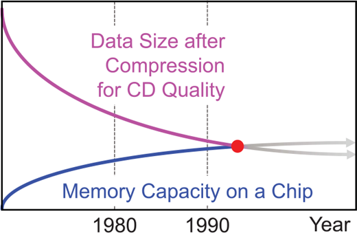
Traditionally, the compressed data had been stored in an optical or a magnetic device such as optical/magnetic discs and magnetic tapes. However, requirements for audio devices needed to include longer recording time and quick random access. In addition, compact size and light weight for easy handling as well as shockproof are also important for portable devices. In view of these requirements, semiconductor memories could be a new candidate. Specifically, it was of general interest to store the compressed data onto a semiconductor-memory card. A portable audio device with a semiconductor memory card was a natural consequence of an intersection between the ever-increasing memory capacity on a single chip and the ever-decreasing number of bits to express a practical length of audio signal with the state-of-the-art audio coding algorithm as shown in Fig. 1. It was 1 December, 1994, when the Silicon Audio made a debut as the world’s first all solid-state portable audio player [10]. It is the ancestor of the iPod as well as the origin of a variety of digital information devices to appear in the following years.
This paper presents the origin of digital information devices, the Silicon Audio, and its family. The Silicon Audio naturally leads to its video derivative, the Silicon View [11], which paved the way to a wider variety of digital information devices including “the iPod with video” [12]. In the following section, conventional audio players are reviewed from a viewpoint of their shortcomings. The new audiodata encoding/decoding system with semiconductor storage is introduced in Section III with its challenges to a successful commercial product in Section IV. Section V presents the Silicon Audio family as promising future digital information devices in those days. Finally, in Section VI, impact of the Silicon Audio on audio players and personal information devices is discussed.
II. Conventional Audio Players
Portable cassette players had been widely used for personal entertainment since Sony released the Walkman in 1979. They use a signal processed and recorded by an analog system; thus, suffer from noise. In late 1980s, digital audio tape (DAT) recorders were introduced in the market which was realized by a digital circuit. However, a common disadvantage of these systems is lack of random-access capability because they are both equipped with a magnetic tape as storage. The tape has to be rewound for playback and fast-forwarded to skip some parts of the contents. CD players were realized based on all-digital technologies in the early 1980s. It supports 20 kHz for the signal as the bandwidth and provides random access. Nevertheless, the mechanical movement in the player causes undesirable skips in the reproduced sound by shakes and vibrations, which degrade sound quality. In addition, the weight and the size were yet other drawbacks of such systems, not to mention power consumption and reliability. An audio player with semiconductor memory had the potential to solve all these problems.
III. The Silicon Audio
A) System features
The Silicon Audio2 [13–15] consists of three parts: an encoder to compress the incoming source signal, a semiconductor card memory to store the compressed data, and a decoder for decompression of the stored audio data to reproduce the original audio signal. The MPEG Layer II algorithm is employed for encoding/decoding. Thanks to this algorithm, a 20-kHz bandwidth, which is equivalent to the CD quality, is supported with minimum audible distortion. The Silicon Audio has no annoying skip in the reproduced sound even with shakes and vibrations because it has no mechanically moving parts. As additional advantages, it is light-weight, compact, and comes with low power consumption thanks to all solid-state implementation, thus, useful in various scenarios with jumps, shocks, and vibrations as illustrated in Fig. 2.

B) Coding algorithm
The coding algorithm is a key to the overall quality of the system. A good algorithm achieves a higher compression rate and requires less memory capacity for the same source signal. MPEG-1/Audio algorithms achieved the better compression rate than other algorithms as demonstrated by subjective evaluations [16, 17]. In addition, they have possibilities to require less cost than other de facto standards for implementation because MPEG is an international standard and was expected to be employed by a larger number of products. The MPEG-1/Audio algorithms have a layered structure with Layers I, II, and III. Among these algorithms, the Layer II algorithm is a good compromise between the compression ratio and the quality of the reproduced signal. Therefore, the Silicon Audio employed the MPEG-1/Audio Layer II algorithm.
The overall encoding and decoding processes of the Layer II algorithm are illustrated in Fig. 3. The incoming linear-PCM (pulse code modulation) data are split into 32 subbands by a polyphase analysis filter bank. Scale factor select information is defined from subband samples and scale factors are calculated. The fast-Fourier-transformed data of the same input signal as to the analysis filter bank are used to calculate masking thresholds based on a psychoacoustic model. The obtained thresholds are used for dynamic bit allocation. Subband samples, quantized with the obtained bit allocation, are formatted with the header and side information into the bitstream.
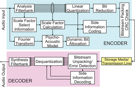
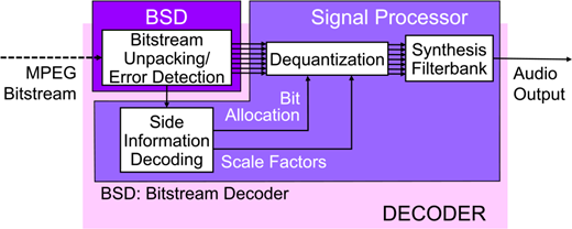
The decoding process could be described by tracing back the encoding process. Before bitstream unpacking, errors are detected by examining the cyclic redundancy code (CRC) check bits. The error correction method is not defined by the international standard and left open for different user requirements. The compressed data are unpacked from the bitstream into the header, side information, and quantized samples. The quantized subband samples are then inversely quantized by the dequantization process with the assigned number of bits. The synthesis filter bank combines the dequantized 32-subband samples into a single full-band signal to reproduce the output signal.
C) Bit rate and recording time
The recording time T in seconds is defined as a function of the memory capacity Mc, the bitrate per channel Br, and the number of channels Nc as
Mc, mc, and Br are expressed in bits, bytes, and bit/s, respectively. Nc is equal to 2 for stereo presentation and 1 for mono. Relations between the memory capacity and the recording time are summarized in Fig. 4 for different bitrates.
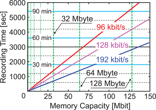
Memory capacity versus recording time (96, 128, 192 kbit/s/ch). Vertical dashed lines represent some typical capacities in mega bytes, wheras the abscissa is expressed in mega bits.
Memory capacity versus recording time (96, 128, 192 kbit/s/ch). Vertical dashed lines represent some typical capacities in mega bytes, wheras the abscissa is expressed in mega bits.
The abscissa and ordinate are the memory capacity in megabits and the recording time in seconds, respectively. Each horizontal dashed line corresponds to 10-min recording and each vertical dashed line is used to show a memory capacity expressed by a power of two such as 32, 64, 128, etc. in Mbyte. The three slant solid lines are the memory capacity versus recording time at 96, 128, and 192 kbit/s/ch. Commercially available flash memory cards had as much as 40 Mbyte (equivalent to 320 Mbit) as the capacity in the mid-1990s. It means that almost 30-min recording was possible at a rate of 96 kbit/s/ch. For 60-min recording, which could be considered as one of the minimum recording times imposed by the consumer requirements, 640 Mbits (80 Mbytes) are necessary as the memory capacity. It was just twice as large a capacity as the current one and did not take long to be achieved by evolving card-memory technologies in those days.
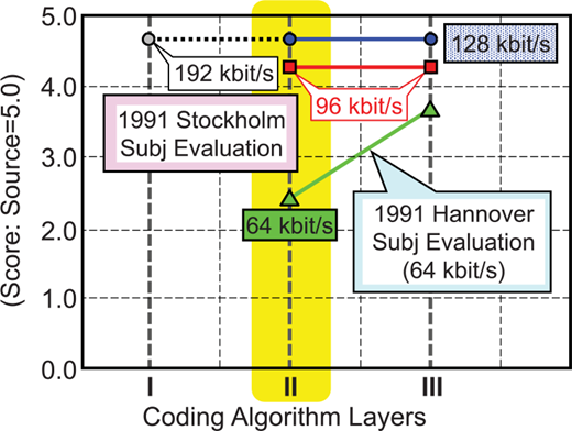
The target bitrates for the Layer II algorithm are 96 and 128 kbit/s/ch. Figure 5 illustrates the results of the two official subjective tests in 1991 [16, 17]. The Layer II provides transparent quality at a bitrate of 128 kbit/s/ch, and some reasonably good quality even at 96 kbit/s/ch. As the Silicon Audio is mainly targeted at general consumers, the incoming data are encoded generally at a bitrate of 96 kbit/s/ch for a reasonable compromise between the recording time and sound quality. However, the bitrate is user-selective from among 192, 128, 96, and 64 kbit/s/ch.
D) Implementation
The first generation in early 1994 was a result of rapid prototyping. The analog circuit for AGC (automatic gain control) and ADC (analog-to-digital conversion) as well as the digital circuit for decoding were separately power-supplied at 15 and 5 V, respectively, for easy implementation. There were no internal batteries so that the power had to be supplied from outside. The second generation prototype in late 1994 was implemented with an MPEG-1/Audio decoder LSI and powered by four 1.2 V nickel metal hydride (NiMH) batteries used for commercial portable audio players.
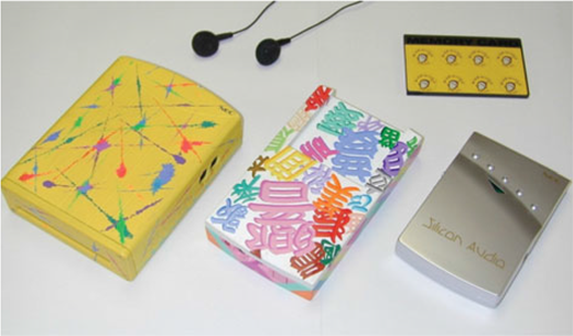
It was not possible to accommodate both encoding and decoding process in a compact portable player. There was no commercial encoder or decoder chip available in the market in the early 1990s. Digital signal processors (DSPs) were not powerful enough to perform both encoding and decoding in real time. Therefore, the play-back-only part with a card memory was implemented as a prototype system. Encoding was carried out either by a breadboard system or a software encoder simulator. Figure 6 depicts a picture of the Silicon Audio developed in the early 1994 [13], late 1994 [14], and 1997 [15].
1) First generation: DSP+gate array implementation
The decoder was implemented by two chips; an NEC’s 24-bit fixed point signal processor (SP) μPD77220 [18], for most of signal processing, and a gatearray chip, called Bitstream Decoder (BSD), for timing generation, bitstream unpacking, and error detection by CRC check. Task distribution between BSD and the SP is depicted in Fig. 7 with an overlapped functional diagram of the Layer II decoder.
Shown in Fig. 8 is a schematic diagram of the Silicon Audio decoder of the first generation. Encoded data, which are stored on a card memory, are retrieved, and converted to serial data. The serial-data bitstream, which is fed to BSD, is first used for synchronization and then, written in RAM1. The data stored in RAM1 are read out, unpacked in BSD, and stored in RAM2. Whenever the synchronization pattern is detected in BSD, a frame synchronization signal is provided with the SP as the reset signal. The interrupt signal and the serial clock signal, both used for output timing, are also provided by BSD.
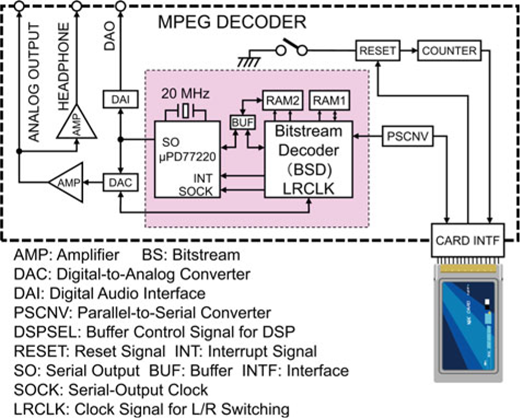
The SP has an access to RAM2 and obtains data therefrom. It is devoted to most of the decoding processes such as side-information decoding, de-quantization of the subband samples, and synthesis of the full-band signal by a filter bank. The SP is operated in the master mode at a machine cycle of 100 ns. The decoded audio sequence is supplied to the digital-to-analog converter (DAC), which both the left and the right channel signals share. Switching between both channels is controlled by a signal generated by BSD. The output signals are then supplied to the output terminals via an analog stereo amplifier. A digital audio interface (DAI) and a terminal for headphones with an additional analog amplifier are also accommodated.
All these LSIs and discrete parts as well as a memory card are accommodated in a package with a dimension of 127 mm × 98 mm × 33 mm. Figure 9 depicts the PCB (print-circuit board) of the Silicon Audio player implemented with a DSP and a gate array chip. The specifications are summarized in Table 2.
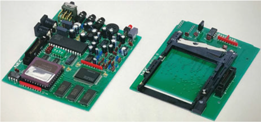
Printed-circuit board of the Silicon Audio player (first generation). Top view (left) and bottom view (right). The SP and BSD are located at the close end of the PCB.
Printed-circuit board of the Silicon Audio player (first generation). Top view (left) and bottom view (right). The SP and BSD are located at the close end of the PCB.
2) Second generation: single chip implementation
The second generation was implemented with only a singlechip MPEG-1/Audio decoder LSI. Features of the decoder LSI are summarized in Table 3. The MPEG-1/Audio decoder LSI [19, 20] conforms to Layers I and II algorithms in ISO (International Standardization Organization)/IEC (International Electrotechnical Commission) 11172-3, known as MPEG-1 Audio. To achieve low power-consumption and single-chip realization, a hardwired approach was employed. The LSI also provides functions to decode Layers I and II LSF (low sampling-frequency) bitstreams of ISO/IEC 13818-3 [21]. The filter bank is designed as a cosine-modulated filter bank [22]. By using the symmetry of the cosine function and a fast DCT (discrete cosine transform) [23], it finally requires 30% multiplications and 37% additions of the original calculation [24].
Features of the decoder LSI.
| Algorithm | MPEG-1/audio layer I/II |
| MPEG-2/audio LSF layer I/II | |
| Bitrate: | All bitrates except free format |
| Sampling frequency: | 16, 22.05, 24, 32, 44.1, 48 kHz |
| Mode: | Stereo, dual-channel, Joint stereo, mono |
| Input bitstream: | Serial/parallel selective |
| Max. operating freq.: | 24.576 MHz |
| Package: | 100-pin QFP |
| Power supply: | 5V |
| Power consumption: | 350 mW |
Shown in Fig. 10 is a schematic diagram of the Silicon Audio player, the second generation. Encoded data, which are stored in a card memory, are retrieved and converted to serial data. The read address of the card memory is controlled by ADRS CTRL. The generated address is generally monotonically increasing, however, it is easy to jump to a new address instantly by a control command. The serial bitstream is fed to the decoder LSI. All the decoding processes such as synchronization, bitstream unpacking, side-information decoding, de-quantization of the subband samples, and synthesis of the full-band signal by a filter bank are performed in the single-chip LSI. The decoded audio sequence is supplied to a DAC, which both the left and the right channel signals share. The output signals are then supplied to the output terminals via an analog stereo amplifier.
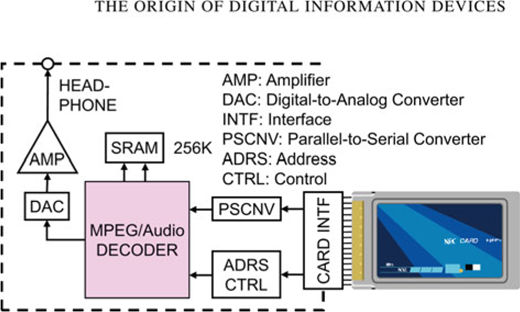
The decoder LSI and peripheral components as well as a memory card and four NiMH batteries are accommodated in a package with a dimension of 130 mm × 78 mm × 22 mm. Figure 11 depicts the PCB of the Silicon Audio player. The audio decoder LSI is located at the close end of the left picture. The specifications of the Silicon Audio player (second generation) are summarized in Table 4.
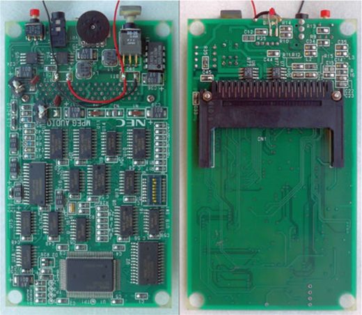
PCB of the Silicon Audio player (second generation). Top view (left) and bottom view (right). The decoder LSI is located at the close end of the left picture.
PCB of the Silicon Audio player (second generation). Top view (left) and bottom view (right). The decoder LSI is located at the close end of the left picture.
IV. Challenges Toward a Successful Commercial Product
The Silicon Audio was a prototype, which had challenges to overcome to make a successful commercial product. They are the memory price, copyright protection, and contents distribution, to name a few. In the mid-1990s, the memory price was not sufficiently low for daily use. In 1993, 1 Mbyte flash electrically erasable programable read-only memory (EEPROM) and 1 Mbyte un-rewritable mask ROM cost $30 and $0.625, which were expected, by extrapolation, to go down as low as $1 and $0.021 per Mbyte by 2000 [25, 26]. To record 60 min of stereo sound, the necessary EEPROM capacity from (1) is 82 Mbytes which would still cost US$82 in 2000, if the prediction based on the inset [26] in Fig. 12 were correct.
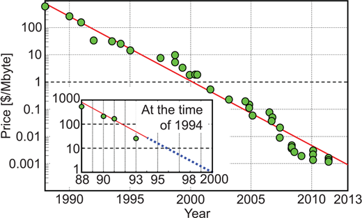
Now, the history tells us that the memory price has been reduced continuously [27] as shown in Fig. 12. With the decline of the memory price, small companies in Korea and Singapore such as Saehan Information Systems, Diamond Multimedia, DigitalCast (Rio), ReignCom (iRiver), and Creative, released portable audio players in the market in the late 1990s and Japanese electronics manufacturers such as Sony, Aiwa, Toshiba, Matsushita (Panasonic), and Sanyo followed in 2000s. The mpman MP F-10 by Saehan was released in 1998 as the first commercial all solid-state audio player. It had 32 or 64 MB internal memory to keep 30 or 60-min music encoded at a bitrate of 128 bit/s, stereo. Because most of them employed MPEG-1/Audio Layer III, also known as MP3, as the coding algorithm, these players are called MP3 players. The AudioKey released in 2003 by Packard Bell, an NEC subsidiary, is one of those products.
The signature portable audio player by Apple, the iPod3, was released in 2001. Even though it was 1 year after the EEPROM price/Mbyte had reached $1 as predicted in Fig. 12, the iPod was equipped with a hard disk drive (HDD) to provide sufficient memory capacity at a reasonable cost. All solidstate audio players by Apple had not been available until the iPod nano was released in 2005.
There was no single popular copyright protection method, thus, each product used its own method in the 1990s. It was because each small manufacturer could not negotiate with multiple content providers in parallel for a comprehensive contract to cover wide range of contents. Users need to collect or encode audio data by themselves piece by piece. Some of consumer electronics companies such as Sony and JVC were bigger than forerunners thus stronger in contract negotiation. However, they had their subsidiary content providers. Those with a subsidiary content provider were reluctant to access content providers outside the family to cover a wider range of contents which are more attractive for users. They spent time and effort to cooperate with each other to achieve a comprehensive contract with content providers. However, it was not easy for them to agree on a common digital rights management method. Apple did not try too hard to agree on a standard digital rights management method with other companies to avoid conflict with others. As a result, Apple was the first to succeed in a comprehensive contract with multiple content providers to implement a one-stop shopping system for audio data. With its iTunes Music Store (currently, iTunes Store) established in 2003, Apple has a share of approximately 80% in 2012 in the music player market.
V. The Silicon Audio Family for Other Applications
A) The Silicon View
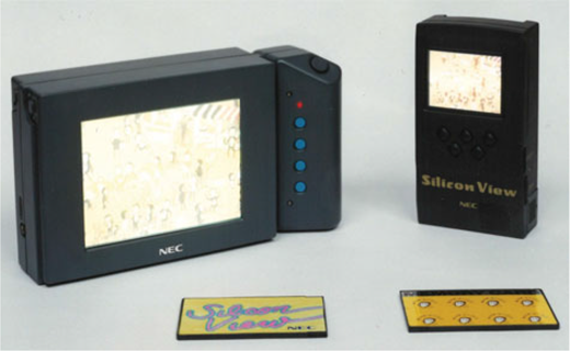
The Silicon View4 is a video extension of the Silicon Audio, which was revealed on 12 October, 1995 [11]. It reads MPEG-1 Video [30] data from a semiconductor memory card, decodes them, and displays the decoded data in an liquidcrystal display (LCD) in addition to the Silicon Audio functions. The Silicon View was developed in two models; a portable model with a 5.5-inch LCD for better video presentation and a hand-held model with a 2.5-inch LCD for the minimum possible size and weight. Their specifications are summarized in Table 5.
Specifications of Silicon View players (portable and hand-held model).
| Version | Portable model | Hand-held models |
|---|---|---|
| Algorithm | MPEG-1 video | Same as left |
| Number of pixels | 352 × 240 max. | Same as left |
| Implementation | μ P D61010 + peripherals | Same as left |
| LCD size | 5.5 inch | 2.5 inch |
| LCD panel | TFT (thin-film transistor) | TN (twisted nematic) |
| LCD resolution | 320 × 240 pixel | 312 × 230 pixel |
| Power consump. | 5 V 800 mA | 5 V 600 mA |
| 9.5 V 700 mA | 3.6 V 300 mA | |
| Power supply | External AC adapters | Lithium ion battery 3.6 V 1300 mAh |
| Dimension | 222 mm × 125 mm × 62 mm | 146 mm × 76 mm × 37 mm |
| Weight | 1000 g | 295 g with battery |
| Recording time | 4 min/40 Mbyte | Same as left |
A recommended bitrate for the compressed bitstream is about 1.4 Mbit/s or 10 Mbyte/min for the video with a resolution of 352 × 240 pixels with a 44.1 kHz sampled stereo audio signal. The compression ratio is 1 /23. When the resolution is reduced to 176 × 120 pixels, the bitrate is one half with twice as long recording time as for the original resolution. The Silicon View player has a video zooming function which automatically displays the video program larger by horizontal and vertical pixel interpolation when the video input has a resolution smaller than 176 × 120 pixels. Use of images instead of moving pictures is possible, which enables approximately a tenfold playback time. Figure 13 illustrates relations between the memory capacity and the recording time for three different modes.
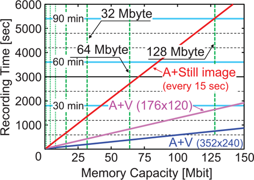
Memory Capacity versus Recording Time for Silicon View with three modes: Audio + still images (every 15 s), Audio + Video (176 × 120 pixels), and Audio + Video (352 × 240 pixels).
Memory Capacity versus Recording Time for Silicon View with three modes: Audio + still images (every 15 s), Audio + Video (176 × 120 pixels), and Audio + Video (352 × 240 pixels).
The Silicon View players consist of a single-chip MPEG-1 Audio/Video (AV) decoder LSI, μP D61010 [31], an address control unit (ADRS CTRL), a timing control unit (TIMG CTRL), a 4-Mbit RAM, a host control unit (HOST CTRL), a pair of DACs and analog amplifiers for the output AV signals, an LCD, and a loudspeaker. Features of the AV decoder LSI and a blockdiagram of the Silicon View players are shown in Table 6 and Fig. 14.
Features of the AV decoder LSI.
| Video decoding | 352 × 240@30 Hz, 352 × 288@25 Hz high-resolution still image (704 × 480 or 704 × 576 pixels) |
| Audio decoding | Stereo at 32, 44.1, or 48 kHz sampling |
| Max. operating freq.: | 27 MHz |
| Package: | 160-pin PQFP |
| Power supply: | 5V |
| Power consumption: | 1.7 W |
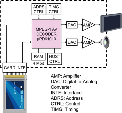
The decoder LSI and the RAM receive an encoded bitstream from the card memory, decode it, and provide the DACs with a digital RGB (red–green–blue) video and a digital audio signal. A timing signal for decoding is generated by the TIMG CTRL unit. The analog AV signals from the DACs are amplified and drives the LCD and the loudspeaker. Addressing for the card memory is controlled by the ADRS CTRL unit which also takes care of the switching signal among “play,” “stop,” “pause,” and “program jump.” The HOST CTRL unit keeps an eye on the LSI status and resets the whole system upon an error. ADRS CTRL unit, HOST CTRL unit and TIMG CTRL unit are implemented by a single-chip microprocessor and a field programable gate array (FPGA). The main decoding PCB for the handheld model is 75 mm × 105 mm. The hand-held model of the Silicon View player operates for 40 min with a built-in rechargeable lithium ion battery. The portable model and the hand-held model of the Silicon View player are depicted in Fig. 15.
B) The Silicon Guide
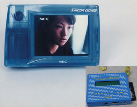
A more specific extension of the Silicon Audio and/or Silicon View is a hand-held guide system which can be carried at an exhibit, a sightseeing spot, or in a museum and tells the user details of the displayed object. The Silicon Guide is such a system. The audio-only model is easier to carry and the audio explanation complements the displayed information. The AV model [32] is heavier, however, provides more detailed information in a more effective way with the mixed media. Multiple programs are played back, each of which contain AV data specific to the display. It has the following functions:
Playback of the programs in the specified order.
Automatic hold after each program.
Repeat of the previous program upon user’s direction.
Quick search for a desired program.
The Silicon Guide provides control of program-playback order and quick random access, which are inevitable for these functions. The specifications of the AV Silicon Guide are summarized in Table 7. Compared with the portable model of the Silicon View, the AV Silicon Guide operates on a single lithium ion battery for up to 90 min. Figure 16 depicts the AV model and the audio model of the Silicon Guide.
Specifications of AV Silicon Guide.
| Algorithm | MPEG-1 video |
| Number of pixels | 320 × 240 dot |
| LCD panel | TFT (thin-film transistor), 5.5 inch |
| Power supply | Lithium ion battery, 7.2 V 2800 mAh |
| Operating time | 90 min |
| Dimension | 128 mm × 200 mm × 55 mm |
| Weight | 900 g (with battery) |
C) The Shopping Navigation
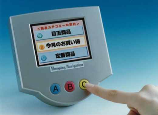
A possible origin of today’s AV streaming terminals attached to a store shelf is the Shopping Navigation [33] which displays detailed information of a suggested product, the most popular product, or an event based on an instruction by the user. The Shopping Navigation, depicted in Fig. 17, keeps playing back the main program with multiple selection indices such as A, B, and C until there is an instruction by the user to change the program. The user can press one of those labeled buttons near the display for instruction. Depending on which of A, B, or C button is pressed, a different program will be played back. Table 8 shows the specifications of the Shopping Navigation.
VI. Impact of the Silicon Audio on Audio Players and Digital Information Devices
The Silicon Audio had an unparalleled impact and was reported in major newspapers and magazines in Japan, USA, and UK such as the Asahi [34], the Nikkei [35], the Financial Times [36], the International Herald Tribune [37], Time [38], and the Future Music [39]. The Silicon Audio opened a new way to solid-state audio players. A decoder (and an encoder at a later time) is implemented by peripherals and an LSI chip which anybody can purchase from a semiconductor company. The necessary number of parts was significantly reduced. Such simplification is clearly demonstrated by comparing Figs 8 and 10. Place a small number of electrical parts on the PCB and float it on the surface of a solder pool. That is the whole assembly process. No integral process for discrete parts based on long and extended experience in assembly is needed. Anybody can start manufacturing business. As a result, small companies as mentioned in Section IV newly started manufacturing audio players. It was a revolution in manufacturing which invited new companies to join and resulted in market expansion in the early stage. It is interesting to see the same thing happening in car industry today. Electric vehicles are like the Silicon Audio in comparison with conventional cars powered by fossil fuels such as gas and diesel fuel.
The Silicon Audio has made significant impact upon personal information devices leading to today and future as illustrated in Fig. 18. Today’s most successful portable audio player, the iPod, was put in the market in 2001. This iPod player employed MPEG-1/Audio Layer III also known as MP3. It took 3 years until the iPod employed MPEG-4/Audio AAC (advanced audio coding) [40] that is today’s most widely used MPEG/Audio standard. It should be noted that the iPod still used an HDD as the memory device. Next year in 2005, Apple released the iPod nano that employed semiconductor memory therein.
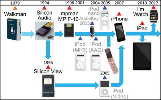
A history of digital information devices: from the Walkman to the Silicon Audio, a smartphone, a tablet, and a smart watch.
A history of digital information devices: from the Walkman to the Silicon Audio, a smartphone, a tablet, and a smart watch.
The next notable step was the release of the iPhone in 2007 that is the first smartphone. It was integration of an audio player and a conventional mobile phone handset with a touch-screen-based intuitive user interface. A smartphone is a commodity consumer product today and is a most promising personal information device in the future. Its display and the keypad are extracted and combined with a wrist watch to make a smart watch. “i’m” released the first smart watch, the “i’m Watch,” in 2011. Another derivative from smartphones is a tablet PC represented by the iPad released in 2010. It is an upscale iPhone with a larger display. Evolution of personal information devices still continues with more applications to come.
VII. Conclusion
The origin of a variety of personal information devices, the Silicon Audio, has been presented with its family. It has a memory card to store the compressed signal by MPEG-1/Audio Layer II algorithm. It has been shown that matured LSI technology to implement a decoder or even a codec on a single chip was essential to the Silicon Audio family in addition to the crossing of ever-increasing memory capacity and ever-decreasing bitrate necessary for satisfactory AV signal quality. With no mechanical movement, it is robust against shakes and vibrations. It has also changed the manufacturing process and companies therein. It is not simply the ancestor of the iPod, but has developed to a smartphone, a tablet PC, and a smart watch. Its evolution as a personal information device still continues with more applications to come.
Supplementary material
To view supplementary material for this article, please visit https://doi.org/10.1017/ATSIP.2017.16.
Walkman is a registered trademark of Sony Corporation.
Silicon Audio is a registered trademark of the NEC Corporation.
iPod, iPhone, iPad, iTunesMusic Store, and iTunes Store are registered trademarks of Apple Inc.
Silicon View is a registered trademarks of NEC Corporation.

