


The study aims to apply reality capture technology to enhance the cost valuation and work verification process of work completed. Construction work completed during the execution phase must be evaluated periodically to ascertain the contractor’s financial resources invested for payment. The manual process is cumbersome and time-consuming, subjective due to human intervention and often results in assumptions complicating accurate and efficient project cost management. Claim disputes and delayed payment usually arise due to a lack of clarity on the value of work completed.
This study used proof of concept on an ongoing construction project to assess the valuation process of work done by using a reality capture (RC) technology – a drone for the acquisition of point cloud data for measurement extraction and valuation of work completed. Works verification was carried out using the as-design digital and as-built point cloud models.
The valuation process becomes dependable, transparent, accurate and efficient using RC technology, which can offer detailed digital data for visual inspection and assessment by all stakeholders. Extraction of quantities of work completed for cost valuation is done using the as-built point clouds obtained from aerial imagery captured by drones.
The study presents a practical solution by integrating RC technology into the cost valuation workflow to increase the correctness, transparency, efficiency and effective process for cost valuation, verification and payment certification. Using the potential of RC technology has enhanced communication, collaboration and coordination among the project stakeholders for seamless and timely payment approvals. This lessens the time for contractors’ claim approval since evidence of work done can be readily accessible remotely.
Abbreviations
- AEC-FM
= architecture, engineering, construction and facilities management;
- BIM
= building information modelling;
- RC
= reality capture;
- 3D
= three-dimensional;
- PCD
= point cloud data;
- UAV
= unnamed ariel vehicle;
- GNSS
= global navigation satellites system;
- GIS
= geographic information system;
- EVA
= earned value analysis;
- DWG
= drawing;
- IFC
= industry foundation classes;
- RVT
= Revit;
- DXT
= drawing exchange format;
- SKP
= SketchUp;
- LAS
= LIDAR aerial survey; and
- RCP
= Revit construction package.
Introduction
In the construction industry, effective payment processes are crucial for maintaining smooth project workflows and ensuring fair compensation for all stakeholders involved. One of the fundamental challenges faced by project stakeholders in construction payment processes is the determination of accurate measurement of quantities of work done (Judi and Mustaffa, 2023). Traditional methods often rely on manual measurements, which are subjected to errors and assumptions and are time-consuming. They often encounter challenges related to inaccurate quantity takeoffs, lack of transparency and delays in documentation, verification and certification.
Emerging reality capture (RC) technologies have been proposed to overcome these limitations and ensure resilient, robust processing. The RC technology allows for replication of the physical world into a virtual environment, allowing professionals to plan, monitor progress and compare as-built models to as-designed models, ensuring quality control (Fobiri et al., 2021).
RC allows for the rapid and precise collection of extensive digital data about project site conditions in three-dimensional (3D) point clouds through various techniques, including photogrammetry, mobile mapping sensor platforms and laser scanners (LECIA, 2018). RC technology, such as drones, 3D laser scanning, 360-degree cameras, mobile mapping systems, global navigation satellite system (GNSS) receivers and structured light scanners, have emerged as transformative tools in the construction industry. These technologies can be used individually or in combination to achieve comprehensive RC for various applications, enhancing accuracy, efficiency and visualization capabilities in digital projects. Drones, also known as unmanned aerial systems/vehicles (UAVs), were first used in the military and have more recently found civilian uses. UAVs are capable of remote or autonomous flight without a pilot. In architecture, engineering, construction and facilities management (AEC-FM), UAVs are increasingly used for data collecting, mapping and visual inspection (Onososen et al., 2023). It has been noted that digitalization can help construction companies establish and optimize the delivery of infrastructure in a field that is limited by a lack of resources, ineffective practices, wasteful material use, schedule overruns and cost overruns (Fagbenro et al., 2022).
To enable accurate distance measurements and the creation of 3D models that can aid in the analysis of significant construction-related data in a variety of formats, including volumes, surface areas and altitudes, high-quality drone images can quickly capture vast aerial data with GPS points in two-dimensional and 3D (Aiyetan and Das, 2023). UAVs use in construction development has surged at a never-before-seen rate (Jeelani and Gheisari, 2021). Digital transformation is one way to achieve resilient and responsive building processes at the speed required to move from traditional development tactics to better and sustainable infrastructure delivery techniques (Onososen et al., 2023). It is critical to acknowledge digitalization as a socio-technical process that leverages digital technology to develop new organizational practices. This will help raise awareness for reskilling initiatives, higher education, industry acceptance and successful government policies. Industry usage of applied digital technology to the built environment processes is limited despite their great benefits.
Novel RC technologies, such as UAVs, are used to guarantee the longevity of civic infrastructures and minimize if not completely eradicate, human casualties and financial losses, hence facilitating efficient techniques for assessing the damage (Munawar et al., 2022). Drones are a major source of support for the structural engineering sector. They are commonly used in construction to finish tasks or inspections in places that are challenging to access. Structural engineers use the UAV’s capacity to acquire high-resolution pictures to precisely evaluate the condition of the roof, skylights, culverts and bridges. Furthermore, studies by Eiris et al. (2020) adopted drones as cracks assessment and inspection techniques. Since crack detection techniques affect a structure’s longevity and safety, they must be dependable, fast and efficient when assessing its health. Traditional (manual) crack detection techniques rely heavily on the procedures and experience of the investigators. Such manual inspection is done using crack analysis, which determines the location and lengths of the cracks. The results are subjective and based on the inspector’s skill level. These limitations lead to inaccurate estimations, which is critical to infrastructure development (Eiris et al., 2020). Similarly, valuation and assessment of work done manually by experienced quantity surveyors can result in errors and subjectivity due to the painstaking, labour-intensive processes.
Drones can be used for various purposes to improve security and safety, including ground safety analysis and progress monitoring. Drones can check difficult-to-reach regions and provide high-resolution photographs to help identify potential threats. Drones can also be used for structural inspections, which lowers the possibility of worker injuries during manual inspections (Jeelani and Gheisari, 2021). They are able to identify architectural flaws or fissures before they become serious problems. Additionally, by promptly and precisely sharing data between various project teams, fostering better collaboration and facilitating prompt and efficient decision-making, drones help to improve data management and communication. Drones can be used in construction project management to increase safety and security, lower the chance of accidents and delays and increase overall work efficiency, all of which save money (Choi et al., 2023; Fan and Saadeghvaziri, 2019). In addition to exceeding owner expectations and cutting project costs through efficient project delivery, it can contribute to the success of a project by speeding up the capture of digital data for design creation and communication with all stakeholders involved, from the owner to the labourer (Fobiri et al., 2022). Despite the potential of RC technology and various applications, little is explored in the area of cost valuation. The purpose of this study is to investigate the use of RC technology as a monitoring tool for the cost valuation and verification of work done for payment in construction projects. This study adopted a case study to highlight the positive impact of using drones, an RC technology, to enhance the valuation and verification process of work done for payment.
Literature review
Reality capture technology – drone applications in the construction industry
The study discusses the use of drones in various stages of application in the construction industry, highlighting the efficiency in surveying and data gathering for designing, building and monitoring a wide range of infrastructures (Salem and Dragomir, 2024).
Efficient surveying and mapping.
Drones are useful instruments for accurately mapping and surveying natural landscapes, offering vital data before implementation to support well-informed planning (Fan and Saadeghvaziri, 2019). The emphasis on precision suggests that by providing decision makers with useful data, drones can help achieve the accuracy needed for successful building projects (Berie and Burud, 2018; Hou et al., 2021).
Efficient design and quality enhancement.
According to Salem and Dragomir (2024), drones are essential for increasing the effectiveness of infrastructure design in building projects through accurate data capture. Drones provide useful information for future designs, boosting safety and flexibility (Fan and Saadeghvaziri, 2019). Post-disaster evaluations, such as assessing damage to a nuclear plant. However, achieving quality comes with its cost (Jaskula et al., 2024), and there is the need to balance the transactional cost with the project budget.
Real-time traffic monitoring.
In the study by Moeini et al. (2017), drones were effectively used to monitor real-time traffic information for planning, management and decision-making. Drones have proved useful for quick and accurate data collection for building new roads and bridges. The economic acquisition of data on vehicle classification based on length highlights the significance of drones in pavement design, particularly when considering size and weight variations. Drones’ involvement in contemporary urban planning is confirmed by their ability to help construct movable bridges, smart cities and lane networks.
Improving construction monitoring and productivity.
The paper offers specific instances of how drones have shown to be useful in monitoring construction projects, ranging from large-scale structures to residential flats. When used with building information modelling (BIM), drones can increase construction productivity by keeping an eye on material delivery and equipment utilization in addition to the construction process (Salem and Dragomir, 2024).
Inspection and maintenance survey of infrastructure.
Drones are a game changer when it comes to inspecting and maintaining infrastructure, contributing significantly to inspection and maintenance activities. The study discusses integrated drone surveying and detection operations, like using wall-sticking drones to inspect crude oil storage tanks, finding concrete crack damage, identifying fatigue cracks in steel bridges, detecting deflection in bridges, analyzing corrosion in towering chimneys and visually inspecting concrete dams (Mattar and Kalai, 2018). The inclusion of wireless detectors integrated with drones, infrared cameras and X-ray cameras emphasizes their potential for examining infrastructure’s hard-to-reach areas (Salem and Dragomir, 2024).
Drones application for construction monitoring, cost valuation and verification.
By using drones to monitor at the proper heights to take clear pictures of project landmarks, the increasing usage of digital twin technology in construction project management guarantees real-time synchronization between actual project development and virtual plans (Feng et al., 2021). The building and construction industry sees a dramatic change in plan execution and project monitoring techniques in light of ongoing technological advancement. Even while traditional methods are still used for project monitoring and execution, they frequently cannot keep up with the last-minute adjustments that are needed (Onososen et al., 2023). On the other hand, digital twin technology, which makes use of smart equipment, is seen as a novel approach that offers precise real-time information reflecting the status of construction (Pal et al., 2023). Conversely, the smart monitoring system makes use of organized real-time data that is gathered through the use of RC technology like drones and installed sensors like infrared, thermal and photo/video cameras. These data are examined using cutting-edge technologies, allowing for improved planning and modification. The following are significant uses of UAVs in construction monitoring (Ullo and Sinha, 2020). This can offer valuable support to the valuation and verification of work done for payment:
Making 3D maps helps supply quick and precise information needed to make 3D models of the construction site. It will be simpler for stakeholders to keep track of developments and give the most recent information kept online for interactive viewing.
3D project surveys and aerial photography make it easier to provide clients with precise and thorough photographs and videos, allowing them to efficiently plan interior and exterior design and monitor progress.
Tracking the development process, which enables the identification of flight paths to give stakeholders regular visual updates that improve communication and transparency.
Aerial and volumetric measurement allows for highly accurate measurements with little interference with regular site operations. The data could be used for work done quantification and cost valuation. This highlights the significance of new technology approaches for construction monitoring, valuation and verification by improving job efficiency for successfully accomplishing project goals.
Construction interim payment processes and challenges
Construction interim payment is a mechanism in construction contracts that allows contractors to receive periodic payments based on the work completed, ensuring cash flow, dispute avoidance and quick payments. It is crucial for the financial stability and smooth progress of projects (Muhammad, 2020). Despite its importance, challenges such as time-consuming evaluation procedures, disputes and inefficiencies persist. The literature review explores these issues and suggests using RC technology as a potential solution to address problems related to timeliness, accuracy and effort reduction in contract administration and payments (Zeng et al., 2021).
Delayed quality assessment process.
Delayed quality assessment can lead to rework, project delays, increased costs and payment delays because the authorizing agent struggles to confirm the quality of work. Late identification of defects or non-compliance disrupts schedules and erodes stakeholder confidence, damaging relationships and trust (Oyebode, 2019; Simard et al., 2023). Clients and investors depend on timely, accurate, quality reports to secure their investments. To mitigate these risks, more frequent and real-time quality assessments are recommended. RC technology like drones, 3D laser scanning and integrated project management software can improve the efficiency and accuracy of quality checks, ensuring issues are promptly addressed and payment approval is expedited (Luhmann et al., 2020; Mahajan, 2021).
Lack of transparency.
Construction cost valuation is a complex process influenced by materials, labour, equipment and unforeseen contingencies. The involvement of multiple stakeholders, contractors, subcontractors, suppliers and consultants can lead to communication gaps and a lack of cohesive information sharing (McHugh et al., 2021). This fragmentation can result in discrepancies between projected and actual costs, making it difficult to accurately assess the project’s financial health.
Costs.
This lack of transparency can cause discrepancies between projected and actual costs. Hidden costs and detailed calculations are crucial but, if poorly managed, can lead to disputes and payment delays. Additionally, vague payment terms and conditions in contracts can cause uncertainty and hesitation among professionals responsible for certifying payment, further complicating the interim payment process (Igwe et al., 2020).
Inaccurate progress measurement and valuation.
Accurately measuring and valuing work progress is essential for determining interim payments in construction projects. Traditional manual methods can result in errors, disputes and biases, causing payment discrepancies, cost overruns and schedule delays (Kim et al., 2024). Inaccurate progress measurement can lead to overpayment or underpayment, creating challenges for stakeholders (Alizadehsalehi and Yitmen, 2019). Human errors and subjective assessments exacerbate these issues. Enhanced accuracy in progress measurement is critical for better project cost management, timely completion and smooth payment processes.
Payment certification and approval delays.
The certification and approval process for interim payments in construction can be lengthy and cause significant issues, such as cash flow problems for contractors, project delays and strained stakeholder relationships (Arowoiya and Fadeke, 2019). Delays often arise from bureaucratic inefficiencies, incomplete documentation and discrepancies between reported and actual work (Sunil and Pathirage, 2015). These delays can financially strain contractors and subcontractors, potentially leading to work stoppages and schedule disruptions, affecting the current project and long-term relationships.
Disputes and non-payment.
Disputes and non-payment often lead to financial instability and project delays since interim payments are made at various project stages, ensuring ongoing cash flow for the contractor and subcontractors to complete the project successfully and on time. Disputes typically arise from disagreement on the quality or quantity of work done, often due to lack of transparency, poor documentation or inaccurate progress reporting. These disagreements can escalate into formal disputes requiring mediation or litigation, further delaying payments and increasing costs for all parties involved (Al Malki and Alam, 2021). Non-payment issues can be detrimental, impacting the ability of contractors to pay their workers, purchase materials and maintain project momentum. This financial pressure can force the contractors to halt work entirely, exacerbating project delays and potentially leading to breaches of contract.
Lack of real-time verification of work done.
The absence of real-time verification in construction projects hampers efficiency, accuracy and timeliness. Real-time verification involves continuous monitoring and immediate confirmation of completed tasks, ensuring adherence to standards and accurate work measurement. Without it, discrepancies between actual and reported progress can cause delays in issue identification and financial inefficiencies, such as premature payment or underpayments. Traditional methods relying on periodic inspections and manual reporting are time-consuming and error-prone, lacking the immediacy needed for proactive decision-making (Alizadehsalehi and Yitmen, 2019; Omar and Nehdi, 2016).
Errors and assumptions in measurement.
Errors and assumptions in measuring work done in construction projects can significantly impact accuracy, costs and overall success. Measurement inaccuracies may arise from human error, faulty equipment, environmental factors and hard-to-reach areas (Almukhtar et al., 2021; Fobiri et al., 2022; Valero et al., 2019). These errors lead to incorrect data being used for payment valuation, resulting in underpayment or overpayment of contractors, compromising project integrity and safety.
Benefits of using digital data capture for cost valuation and monitoring
The application of RC technology provides accurate and reliable digital data for progress monitoring, progress measurement and valuation of work done. This enhances transparency, reduces disputes, reduces human intervention, gives real-time construction visualization, verification and approval and improves payment accuracy. Below are some of the immense benefits digital data offer to construction cost management.
Remote assessment and verification of work done.
The COVID-19 pandemic accelerated the shift towards remote work, making it a key aspect of modern work culture (Mahajan, 2021). RC technology enables stakeholders to connect and conduct remote assessments, using high-resolution scans and 3D models to provide accurate data on construction sites (McHugh et al., 2021; Pejoska et al., 2016). This approach reduces the need for on-site visits, saves time, cuts travel costs and ensures accurate monitoring. Real-time data from drones and scanners facilitate quicker decision-making and payment approvals, supporting continuous monitoring, quality control and transparent project management (Sila et al., 2024).
Seamless by reducing human intervention.
RC technology enhances cost valuation, verification and payment processes in construction projects by reducing human intervention and increasing efficiency. Using advanced digital tools like drones and real-time data analytics, stakeholders can streamline operations, improve accuracy and enhance project lifecycle efficiency (Jeelani and Gheisari, 2021). Automated data collection minimizes human error and provides reliable data for cost valuation and payment approval. Drones with high-resolution cameras facilitate seamless verification by capturing detailed images that can be compared against the digital model to ensure completion and adherence to specifications (Noruwa et al., 2020). This RC technology promotes efficient and transparent project measurement, benefiting all stakeholders.
Transparency in the payment process.
RC technology, including laser scanning and drone-based photogrammetry, enhances transparency, accuracy and efficiency in construction projects. It provides detailed digital data for visual inspection and assessment, creating an objective record of completed works (Omar and Nehdi, 2016). High-resolution scans and 3D models offer clear evidence of progress, reducing ambiguities and enabling remote assessment to prove work done. This speeds up payment approval and possible future automation of payment procedures (Rubio et al., 2018). Real-time updates and continuous monitoring streamline the verification process, minimizing disputes and ensuring timely payment for contractors.
Real-time construction visualization, verification and approval.
Advancements in RC technology have revolutionized the creation of 3D digital models for construction projects, allowing for detailed as-built models to be produced remotely before physical site visits (Jacob-Loyola et al., 2021; Jaskula et al., 2024). This technology integrates parametric data and provides a comprehensive, sign-source model for project execution. Remote access to these models enhances safety, communication and design verification. RC technology improves efficiency in data collection, supports payment claims with clear visual evidence and reduces on-site delays. It facilitates better facility management and dispute resolution through detailed, irrefutable documentation of the construction site (Rashdi et al., 2022; Regona et al., 2022).
Improve work done assessment and payment approval.
Traditional methods for valuing completed works and processing payment rely on paper reports and manual, time-consuming processes, often leading to disputes and inefficiencies (Fobiri et al., 2022). RC technologies, such as drone-based photogrammetry, enhance accuracy and efficiency in work assessments (Faremi and Ogunsanmi, 2019). They provide high-resolution scans and detailed 3D point cloud models, offering a precise, objective record of progress; this improves cost valuation, streamlines payment approvals, reduces discrepancies and accelerates the payment cycle. Enhanced documentation fosters trust and collaboration among stakeholders, leading to a more transparent and efficient process (Chalhoub et al., 2021).
Methodology
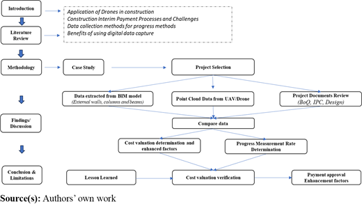
The methodology section outlines the process of monitoring, measuring and evaluating the cost of work done and verification and certification for payment. The study adopted a case study to achieve the aim. Using aerial imagery captured by drones and processed into point cloud data (PCD) for assessment. The following steps were used to carry out the case study as per Figure 1:
the study first conducted a comprehensive review to investigate the feasibility of using RC technology like drones to improve payment processes for contractors’ claims;
the case study project was selected based on the predefined criteria;
obtaining approval and consent from the project owner;
obtaining project documents;
create a digital model (BIM) for the case building;
the PCD of the case building was captured using a UAV/drone;
data analysis and field validation. The PCD was georeferenced with the BIM model and compared for verification, quality and work progress;
identification of the completed activities selected from the BIM model;
identification of the selected completed component from the PCD;
extraction of the quantities from the valuation document;
determination of the work done quantities from the digital data (PCD);
comparison quantities from project valuation and PCD;
determination of progress measurement rate; and
lesson learned on factors enhancing cost valuation, verification and payment approval and associated limitations.
Case study
This study used proof of concept on an ongoing construction project to evaluate the cost valuation, verification and payment process of work done using RC technology.
Project selection
The criteria for the selection of the building were as follows: the building must be an ongoing construction site with some completed activities for the valuation process and payment. Must have external construction activities where the application of the drones can take the digital data since it can only capture exterior and spatial data. Availability of project data for the study. Table 1 shows the overview of the case building.
Approval and consent for the case building
The request to use the case building was obtained from the project stakeholders, indicating the study purposes and the archives document needed. Approval and consent were given for the study.
Obtaining project documents
The researchers sought permission and were granted access to the valuation documents, which included project design, bill of quantities (BoQ) specifications and construction schedules for the study.
Digital model development
The digital model (BIM) for the case of the building was created, a 3D model consisting of geometric developed using Revit as per the project design and specification. The BIM model is georeferenced to the coordinate system by the project. BIM technology can manage the project life cycle and improve project quality and efficiency, reducing project costs, reworks and wastes (Danso et al., 2024). Care was taken to ensure that the model represents the exact design information received and was verted by the project designer to ensure conformity. Appendix 1 shows the as-design 3D digital model of the case building.
Point cloud data
The PCD of completed works of an ongoing construction site of a case building was captured using a UAV/drone. The exterior portion of the building was captured to cover the current completed construction activities for payment. The exterior portion was selected due to the drone’s inability to capture interior areas. The application of the drone includes considering a suitable drone location and positioning, optimizing scanning methods and parameters, processing the data and removing the noise data. The drone/UAV plays a vital role in enhancing the monitoring of construction projects, which the study aims to adopt to improve the cost valuation and verification for payment processes using a proof of concept. MAVIC 2 Pro drone was used to capture the digital data. Appendix 2 and 3 indicate the specifications of the drone used and the setting of the drone for operation.
Pre-flight checks
MAVIC 2 Pro drone was used to capture images of the study areas. Before the commencement of the capture, the following pre-flight checks were carried out:
Battery and propeller inspection: Before each flight, a thorough inspection of the battery and propellers was done. It ensured that the battery was fully charged and free of any damage or defects.
Compass calibration: Compass calibration was done to ensure the drone’s flight stability.
Weather conditions: The weather was checked to ensure that it was not windy and was appropriate for the flight to obtain high-quality images.
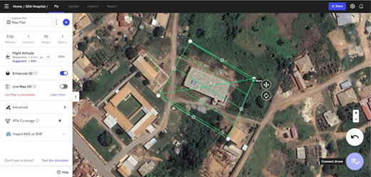
Flight planning: The flight path was planned meticulously, factoring in obstacles, sensitive areas and no-fly zones to avoid drone crashes (see Appendix 4).
Precautions taken during drone operations.
Before, during and after the flying of a drone for an ongoing construction project, the under-listed precautionary measures were taken to ensure safety, efficient drone operations, compliance with regulations and the successful capture of the digital data for the study, minimizing risks to both personnel and equipment.
Pre-flight precautions.
Regulatory compliance: The permit and certification to operate a drone were obtained. The local and national aviation regulations were strictly complied including the construction site policies.
Weather conditions: Weather forecasts for conditions that might affect drone operations, such as high winds, rain or extreme temperatures, were monitored for the selection of the day for the drone operation. This is crucial to prevent accidents and equipment damage.
Site survey and risk assessment: A thorough site survey was conducted to identify potential hazards such as power lines, cranes and other construction equipment. This informed our flight planning to avoid such obstacles and ensure a safe flight path.
Drone inspection: Pre-flight inspections were carried out to check for any mechanical or technical issues. We also ensured that all four batteries were fully charged and all components functioned correctly. The battery adapter was carried along.
Notification and coordination: The construction site manager and workers were informed about the drone operation schedule. To minimize disruption and enhance safety, the site activities were coordinated. During the drone operation day, there were no external activities.
In-flight precautions.
Maintain line of sight: The drone was kept within the visual line of sight to help maintain control and avoid collisions. A spotter was used to help monitor the drone’s position.
Altitude and distance: The drone was flown to a safe altitude that allowed for a clear data capture while ensuring all obstacles were avoided, bearing in mind the adherence to regulatory limits in the region.
Controlled environment: There were no external activities during drone operation to avoid flying directly over workers or populated areas to reduce the risk of injury in case of a drone malfunction. The geofencing features were used to create virtual boundaries during flight planning to prevent the drone from entering restricted or hazardous areas.
Real-time monitoring: A live feed monitoring device was used to keep track of the drone’s position and surroundings during data capture operations. Preparation to take any immediate action should the drone encounter any issues or unexpected obstacles was made.
Post-flight precautions.
Data back up: The captured data was backed up immediately to prevent data loss or corruption. The data were reviewed for quality and completeness, ensuring that all necessary information needed for the cost valuation has been recorded.
Drone maintenance: The drone was inspected for any damage or wear after use to carry out any necessary maintenance if required. Batteries were recharged to prepare for the next flight.
Incident reporting: Incidents or near-misses during the flight were documented. It was observed that the drone was moving out of the defined route. This call for the drone returned and was made to restart the capture. There was an issue of emergency landing due to a low battery. The drone was returned and landed to replace the battery.
Drone aerial imaging
Appendix 5 shows some of the aerial images taken during the flight operation of the drone.
Data processing – point cloud data
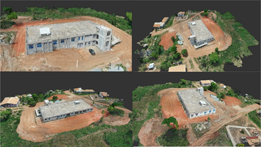
After capturing the images, they were processed using Agisoft Metashape, an advanced software that converts still photographs into high-quality 3D objects. Agisoft Metashape is a stand-alone software programme that processes digital images photogrammetrically and creates 3D spatial data for use in GIS applications, documentation of cultural heritage, production of visual effects and indirect measurements of objects at different scales. The main objective was to produce a point cloud and a textured 3D model. Firstly, a new project was created, and the captured photos were imported. To ensure accurate results, an evaluation of photo quality was conducted to clean out any blurred or distorted images. Once this assessment was completed, software algorithms aligned all photos accordingly by using the GNSS receiver positioning data that was initially captured during image acquisition recording in their metadata. Next, the photos were subject to relative orientation, using specific criteria for optimal outcomes. The alignment’s precision was set to highest while using the reference option during pair preselection. Although setting the accuracy to the highest increases processing time, this was necessary since the software uses the original photo size to compute camera positions with the highest accuracy possible. The reference option also helps to save processing time by detecting overlapping pairs of photographs based on the estimated position provided by the GNSS receiver. The alignment process produces a sparse point cloud. The second stage of photo processing with Agisoft Metashape involved creating a dense point cloud. The software used estimated camera positions to generate depth information for all cameras, amalgamating them into a single high-quality result through the use of filtering algorithms. During this process, depth maps were constructed for each image; however, some images may contain outliers due to being noisy or poorly focused. We opted for more gentle filters under our selected depth filter option to mitigate these issues while retaining important spatial details in the reconstructed scene. Finally, the point cloud and the textured 3D model were exported in the rcps, .las and .fbx formats. UsBIM.browser was used to import the point cloud file for further analysis (see Appendix 6).
Computing areas from the point cloud digital model for smart cost valuation
The Point Cloud offers a fresh method for leveraging cutting-edge aerial surveillance tools to follow and monitor the progress of work done on construction projects and take measurements to evaluate for payment. A case study of a building project constructed with a reinforced concrete structure and block walling units for health-care provision was selected. The selected completed activities are external wall rendering, plinth, columns and beams for the basement and ground floor. Various software applications exist for measurement extraction from the point cloud. Examples are PIX4D, UsBIM.browser, Autodesk recap software, etc. However, UsBIM.browser was used to evaluate the PCD, the distance and area measurement taken to quantify the work done. Various dimensions of the walls, columns and beams were extracted from the point cloud to calculate the areas, as shown in Table 2. UsBIM.browser is ACCA software that allows you to seamlessly manage the entire BIM process online and view 3D models, data and documents in a variety of formats. It opens and manages a wide range of 3D file formats, including DWG, IFC, RVT, DXF, EDF, SKP, LAS, RCP and others, without requiring BIM or Point Cloud viewer software (Revit, Archicad, Allplan, etc.).
Comparing quantities of project valuation and point cloud data
| Item | Completed works/ activities | Unit | BIM quantity | Point cloud quantity | Variance | % variance | |
|---|---|---|---|---|---|---|---|
| External finishes | |||||||
| 13 mm thick cement and sand rendering (14) on external surfaces as described in: | |||||||
| A | Basement | Walls | m2 | 88 | 85 | 3 | 3 |
| Beams | m2 | 23 | 21 | 2 | 9 | ||
| Columns | m2 | 24 | 23 | 1 | 4 | ||
| B | Ground floor | Walls | m2 | 260 | 254 | 6 | 2 |
| Beams | m2 | 69 | 62 | 7 | 10 | ||
| Columns | m2 | 58 | 53 | 5 | 9 | ||
| C | Plinth | Walls | m2 | 107 | 105 | 2 | 2 |
| Columns | m2 | 17 | 14 | 3 | 18 | ||
| Average | 7 | ||||||
Computing areas of the completed sections from point clouds requires a methodical approach that uses these technologies to produce precise measurements and mapping. UsBIM.browser makes calculating the area inside the specified bounds in the point clouds easier. The software uses algorithms to decipher the spatial data from the point cloud and establish the bounds of the region of interest. The computed area is then displayed as an output, offering a precise measurement derived from the drone’s point clouds. Thanks to this integrated technique, the intended region was measured and mapped with a high degree of accuracy. The method used to measure the structure’s distances and surface area of completed works is demonstrated in Appendix 7. The comparing quantities of the PCD and the as-design BIM data are shown in Table 2.
Table 3 indicates the determination of the value of work done using quantities extracted from PCD and unit rate from the obtained BoQ. The unit cost of GHS 40.00 is a contractually agreed price, which consists of the cost of material, labour and plant needed by the contractor for the execution of the work, including overheads and profit mark. The summation of each component amount determines the value of work done for the payment claim. The total value of work done was GHS 24,680.00.
Valuation of work done using quantities extracted from point cloud data
| Item | External completed works/activities | Point cloud quantity | Unit | Unit cost (GHS) | Total amount (GHS) | |
|---|---|---|---|---|---|---|
| External finishes | ||||||
| 13 mm thick cement and sand rendering (14) on external surfaces as described in: | ||||||
| A | Basement | Walls | 85 | m2 | 40.00 | 3,400.00 |
| Beams | 21 | m2 | 40.00 | 840.00 | ||
| Columns | 23 | m2 | 40.00 | 920.00 | ||
| B | Ground floor | Walls | 254 | m2 | 40.00 | 10,160.00 |
| Beams | 62 | m2 | 40.00 | 2,480.00 | ||
| Columns | 53 | m2 | 40.00 | 2,120.00 | ||
| C | Plinth | Walls | 105 | m2 | 40.00 | 4,200.00 |
| Columns | 14 | m2 | 40.00 | 560.00 | ||
| Total cost of works completed | 24,680.00 | |||||
Earn value analysis
Construction work progress measurement is determined by taking the quantities from the database. The actual selected activities identified in the PCD and the BoQ were used to determine the work progress.
The earned value (EV) of work completed to GHS 24,680.00, which was constructed out of the total external rendering works of the case building, cost GHS 50,600.00; therefore, work progress is 51.23%. This is because construction of the first-floor works was yet to commence, so the external works cannot be measured when capturing the data, as shown in Table 4 and Appendix 8.
Computation of earned value in the case
| Item | External completed works/activities | Total quantity | Measured quantity | Unit | Unit cost (GHS) | Total amount (GHS) | Measured amount (GHS) | |
|---|---|---|---|---|---|---|---|---|
| External finishes | ||||||||
| 13 mm thick cement and sand rendering (14) on external surfaces on | ||||||||
| A | Basement | Walls | 88 | 85 | m2 | 40.00 | 3,520.00 | 3,400.00 |
| Beams | 23 | 21 | m2 | 40.00 | 920.00 | 840.00 | ||
| Columns | 24 | 23 | m2 | 40.00 | 960.00 | 920.00 | ||
| B | Ground floor | Walls | 260 | 254 | m2 | 40.00 | 10,400.00 | 10,160.00 |
| Beams | 69 | 62 | m2 | 40.00 | 2,760.00 | 2,480.00 | ||
| Columns | 58 | 53 | m2 | 40.00 | 2,320.00 | 2,120.00 | ||
| C | Plinth | Walls | 107 | 105 | m2 | 40.00 | 4,280.00 | 4,200.00 |
| Columns | 17 | 14 | m2 | 40.00 | 680.00 | 560.00 | ||
| D | First floor | Walls | 260 | 0 | m2 | 40.00 | 10,400.00 | – |
| Beams | 69 | 0 | m2 | 40.00 | 2,760.00 | – | ||
| Columns | 58 | 0 | m2 | 40.00 | 2,320.00 | – | ||
| Parapet wall | 232 | 0 | m2 | 40.00 | 9,280.00 | – | ||
| Total cost of external finishes | 50,600.00 | 24,680.00 | ||||||
Efficient verification and certification for payment
To guarantee that the inspection and verification of work done proceed precisely, smartly and effectively, modern construction technology to enhance visualization and transparency is crucial. To compare the work done at the valuation stages, the PCD, the as-built digital model, were imported into the REVIT software and embedded in the as-design digital model (BIM model) (see Appendix 8). The point cloud processing software offers tools for automatic alignment, which was imported into Revit with the correct coordinates. After removing noise from the data, the PCD was georeferenced with the BIM model and compared for verification, quality and work progress. Visual comparison was carried out using overlay visualization and section boxes to create specific views for comparison. Colour coding of different elements in the Revit model to distinguish them from the PCD for easier comparison. Measuring and analyzing discrepancies were achieved by measuring distances between the point cloud and the Revit model.
The findings show that this novel RC technology has promising project cost valuation capabilities to promote sustainable cost management. The comparison of as-built and as-design offers a real-time remote construction progress status visualization by stakeholders. The results imply that visualization of the completion stage can be assessed remotely, offering stakeholders confidence in approving contractors’ payments with a prompt and seamless process. Construction progress measurement, works verification, cost valuation and cost monitoring have advanced significantly with the integration of RC technology. By providing a methodical way to guarantee that project goals are accurately accomplished, this methodology closes the gap between virtual planning and actual project execution for sustainable infrastructural development. Modern innovations in the area of digitalization have promised a more efficient means of handling verifications. Some advanced tools for deviation analysis can be used as third-party add-ins, such as ClearEdge3D’s EdgeWise, Leica 3DR and NavVis.
Discussions
Incorporating RC technologies into the cost valuation workflows can greatly improve project cost management. Drone provides aerial imagery for as-built PCD, enhancing accuracy and efficiency in progress monitoring, inspection, verification and measurement for cost valuation. Further, it provides project participants with the real-time details of ongoing construction activities, improving communication, collaboration, transparency and understanding, aiding in data-driven decision-making and enabling stakeholders to quickly and effectively assess real-time data for verification and payment approval (Fobiri et al., 2024; Muhammad et al., 2024). The case study results highlight some important points and strongly agree with the body of current knowledge.
Enhancements in transparency and communication for quick payment verification and approval
The case study findings are related to the literature (Fobiri et al., 2022; McHugh et al., 2021; Pica and Abanda, 2019), which highlights how productivity can be increased by increasing transparency and communication among all project stakeholders. Using the as-built model to prepare cost valuation and verification reports for stakeholders improves communication and transparency among the parties involved. In the case study, it was easier to monitor, inspect, assess, quantify and verify work done for payment, improving project stakeholder communication.
Better collaboration and well-informed decision-making
Using RC technologies promotes better collaboration and well-informed decision-making throughout the project lifecycle, in addition to increasing efficiency and accuracy. It offers a high level of detail and accurate project data, which are easily visualized and remotely accessible by stakeholders (LECIA, 2018; McHugh et al., 2021). This enables well-informed decision-making for the successful project cost performance and the overall project success. Drones and other sophisticated tools have made it possible to integrate aerial imagery, representing a state-of-the-art technological development that has greatly improved the accuracy and efficiency of infrastructural delivery. This strategy has produced significant advantages that have improved engineering operations and decision-making procedures.
Detailed site evaluation of work done
Better site comprehension is made possible by digital data, which provides thorough data on terrains, accessible spaces and potential barriers. This enhances the measurement and quantification of work done for cost valuation preparation, ensuring fair work value, thus not overvaluing the work completed at the client’s disadvantage or undervaluing at the disadvantage of the contractor (Fobiri et al., 2022). This helps sustain the project cash flow and mitigate discrepancies that might escalate project costs.
Enhanced accuracy and efficiency on cost valuation
Accurate digital data acquisition by RC technology improves workflow efficiency through precise analysis and inspection of PCD. The case study illustrates how cost valuation procedures have improved and how efficiency is in line with research (Craggs et al., 2016; Mahajan, 2021). By closing the gap between expectations and reality, it helps reduce errors and delays by using drone technology. Through routine monitoring, drones offer a thorough understanding of the project lifecycle, improving efficiency and decreasing errors.
Time and effort savings on valuation of work done
By eliminating the need for human surveying, using RC technologies for digital data saves time and effort. Due to the complex nature and enormous work activities, manual data acquisition for measurement and quantification becomes laborious, time-consuming, error-prone, subjective and frequent site visits (Almukhtar et al., 2021; Fobiri et al., 2022). The introduction of the RC technology cut down the professional time spent on data acquisition, and one capture offers a high level of detail that can be referred to during valuation. Operational safety and risk reduction are improved by identifying safe locations and possible hazards.
Implications of findings
The findings underscore the transformative impact of RC technologies on cost valuation workflows, emphasizing improved accuracy, efficiency and transparency. The proposed methodology has practically demonstrated how RC technologies can transform construction cost management practices. By integrating drones and digital as-built models, the methodology facilitates real-time monitoring, precise cost assessments, effective communication and better collaboration among stakeholders, enabling informed decision-making and streamlining payment verification. Automated digital acquisition saves time, mitigates risks and ensures fair cost assessments, promoting cash flow sustainability. This emphasizes technology-driven innovations by providing a scalable, data-driven framework for improving cost valuation workflows. These advancements align with industry trends, fostering well-informed decision-making and operational safety. This approach exemplifies the potential of innovative technologies to enhance construction practices and research.
Practical implications
Implementing RC technology, like drones, in construction projects offers numerous benefits. It enhances measurement accuracy and data collection, leading to precise cost valuation and work verification. Providing detailed visual and digital verification of completed works reduces disputes and claims between contractors and clients. It also saves time and labour costs associated with manual verification methods, resulting in overall cost savings for the project. Continuous monitoring ensures high construction quality standards and helps promptly address deviations or quality issues. Other advantages include real-time progress tracking, improved compliance with regulatory standards and better resource management. RC technology significantly enhances efficiency, accuracy and transparency in construction project cost management.
Conclusion
Construction interim payment is essential for maintaining financial stability and ensuring project progress. However, challenges such as inaccurate valuation of work done, lack of transparency, payment approval delays and disputes hinder its effective implementation. By the application of RC technologies, these challenges can be mitigated, leading to a more efficient and equitable interim payment process. A case study of an ongoing building project was used as a proof of concept. As-built digital data of completed works was acquired using the drone, while the as-design models were developed using Revit. The selected external activities were a wall, column and beam rendering for the plinth, basement and ground floor. Data extraction from the PCD was carried out to measure areas of the selected external activities. Cost valuation computation was carried out using the unit rate. Distance comparison between the as-design model and as-built model for the determination of variance resulted in a variance of 7%. Earn value analysis computations were used to determine the progress status rate of the completed works, which was 51.23%. Further, the verification of work completed and a comparison of as-design and as-built were performed using Revit.
RC technologies greatly enhance the interim payment process by improving accuracy, speed and transparency. They provide detailed 3D point cloud representations, which aid in as-built documentation, progress monitoring, accurate measurement, visualisation and verification. This innovative integration reduces disputes, improves cost valuation and speeds payment while boosting efficiency and a collaborative platform for teamwork, communication, coordination and cooperation among stakeholders, ultimately benefiting the entire project.
There are a few restrictions on this study. Firstly, the progress status measurement only depended on the outcomes of EVA computations; a more thorough investigation incorporating additional variables will be required. The use of drones for the digital data acquisition since the work completed activities were external works; however, combining with 3D laser scanning would give the entire or complete capture for the construction project activities since they complement each other for better output. Also, 360 cameras would be used for indoor capture to enhance virtual inspection of work done. This methodology can be integrated with construction progress monitoring approaches to get more accurate and evident-based valuation claims.
Furthermore, the case could have benefited from the advanced technology software for the construction verification and deviation analysis, which were unavailable to researchers. Finally, from the case study, it can be concluded that the application of RC technology can revolutionize construction payment valuation processes by providing accurate as-built digital data, enhancing visualization, transparency and real-time project data sharing among project stakeholders, streamlining documentation processes, enabling quick cost verification and payment approval. As the construction industry embraces technology-driven solutions, leveraging RC technologies in cost valuation, payment verification and approval processes holds immense potential to streamline workflows, reduce disputes and foster collaborative relationships within the construction ecosystem.
The work is supported and part of collaborative research at the Centre of Applied Research and Innovation in the Built Environment (CARINBE), University of Johannesburg. The authors wish to acknowledge the University of Johannesburg for the resources used to conduct this study.
Appendix 1
Appendix 2
Appendix 3
Appendix 4
Appendix 5
Appendix 6
Appendix 7: Point measuring distance and calculating areas of completed works using point cloud data.
Appendix 8
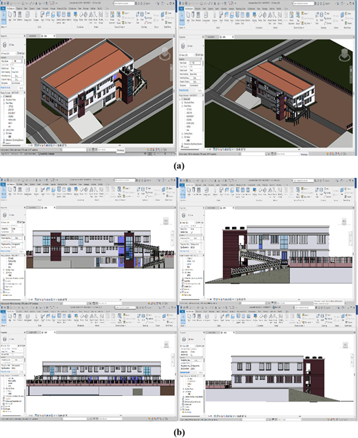
Digital model (BIM) development of case building (3D model and elevations)
Digital model (BIM) development of case building (3D model and elevations)
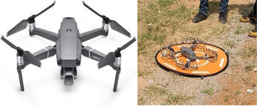
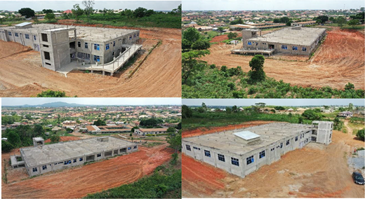
Aerial images taken by the drone showing the completion stage of the work
Aerial images taken by the drone showing the completion stage of the work
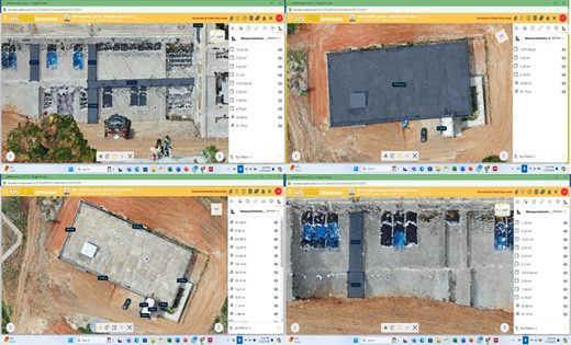
Measuring distance and calculating areas of completed works using point cloud data
Measuring distance and calculating areas of completed works using point cloud data
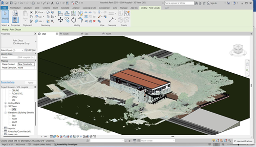
Showing point cloud data embedded on the BIM model for assessment of work done for payment and compared for verification, quality and work progress
Showing point cloud data embedded on the BIM model for assessment of work done for payment and compared for verification, quality and work progress
Drone specification
| Type | MAVIC 2 Pro |
|---|---|
| Sensor | 1” CMOS Effective pixels: 20 million |
| Lens | FOV: about 77o 35 mm format equipment: 28 mm Aperture: f/2.8–f/11 Shooting range: 1 m to ∞ |
| So range | Video: 100–6,400 Photo: 100–3,200 (auto) 100–12,800 (manual) |
| Shutter speed | Electronic shutter: 8–1/8,000 s |
| Still image size | 5,472 × 3,648 |
| Still photography modes | Single shot Burst shooting: 3 / 5 frames Auto exposure bracketing (AEB): 3 / 5 bracketed frames at 0.7 EV bias Internal (JPEG: 2 / 3 / 5 / 7/10 / 15/20 / 30/60 s RAW: 5 / 7/10 / 15/20 / 30/60 s) |
| Video resolution | 4K: 3,840 × 2,160 24 / 25/30p 2.7K: 2,688 × 1,512 24 / 25/30 / 48/50/60p FHD: 1,920 × 1,080 24 / 25/30 / 48/50 / 60/120p |
| Max video bitrate | 100 Mbps |
| Color mode | Dlog-M (10 bit), Support HDR video (HLG 10 bit) |
| Sensing system | Omnidirectional obstacle sensing 1 |
| Forward | Precision measurement range: 0.5–20 m Detectable range: 20–40 m Effective sensing speed: <14 m/s FOV: horizontal: 40°, vertical: 70° |
| Backward | Precision measurement range: 0.5–16 m Detectable range: 16–32 m Effective sensing speed: <12 m/s FOV: horizontal: 60°, vertical: 77° |
| Upward | Precision measurement range: 0.1–8 m |
| Downward | Precision measurement range: 0.5–11 m Detectable range: 11–22 m |
| Sides | Precision measurement range: 05–10 m Effective sensing speed < 8m/s FOV: horizontal: 80°, vertical: 65° |
| Operating environment | Forward, backward and sides: Surface with clear pattern and adequate lighting (lux > 15) Upward: detects diffuse reflective surfaces (>20%) (walls, trees, people, etc.) Downward: surface with clear pattern and adequate lighting (lux > 15) Detects diffuse reflective surfaces (>20%) (walls, trees, people, etc.) |

