

Transfer relations represent analytical solutions of the linear theory of circular arches, relating each one of the kinematic and static variables at an arbitrary cross-section to the kinematic and static variables at the initial cross-section. The purpose of this paper is to demonstrate the significance of the transfer relations for structural analysis by means of three examples taken from civil engineering.
The first example refers to an arch bridge, the second one to the vault of a metro station and the third one to a real-scale test of a segmental tunnel ring.
The main conclusions drawn from these three examples are as follows: increasing the number of hangers/columns of the investigated arch bridge entails a reduction of the maximum bending moment of the arch, allowing it to approach, as much as possible, the desired thrust-line behavior; compared to the conventional in situ cast method, a combined precast and in situ cast method results in a decrease of the maximum bending moment of an element of the vault of the studied underground station by 46%; and the local behavior of the joints governs both the structural convergences and the bearing capacity of the tested segmental tunnel ring.
The three examples underline that the transfer relations significantly facilitate computer-aided engineering of circular arch structures, including arch bridges, vaults of metro stations and segmental tunnel rings.
1. Introduction
The curvature of arches renders their structural analysis more challenging and expensive than that of straight beams. Transfer relations, representing analytical solutions of the linear theory of slender circular arches, were developed by Zhang et al. (2017). They are arranged, in a matrix-vector form, as follows: an 1 × 7 vector on the left-hand side, containing the kinematic and static variables at an arbitrary cross-section of the arch, is obtained as the product of a 7 × 7 matrix and an 1 × 7 vector, containing the kinematic and static variables at the initial cross-section of the arch. They serve as a powerful tool for structural analysis of arch structures.
The present paper is focused on structural analysis of three exemplary arches, based on the transfer relations.
Structural analysis of an arch bridge is the topic of the first example. In case of arches with low degrees of static indeterminacy and specific types of external loads, bridge designers may prefer analytical methods for structural analysis to numerical method. Concerning analytical methods, Fox (2000) reviewed the one of consistent deformations for pinned arches, which are statically indeterminate to the first degree. Melbourne (2008) presented a method based on Castigliano’s second theorem. Dym and Williams (2011) derived the governing differential equations of arches based on Sanders’ shell theory (Sanders, 1961) and variational calculus (Dym and Shames, 1973). Solutions of these equations for pinned or clamped arches, under radial and gravitational line loads, and for shallow arches, subjected to a concentrated axial load, acting at the end of the arch, were presented in Dym and Williams (2011) and Dym (2011). In most cases, arch bridges are complex in terms of boundary conditions and types of external loads, necessitating the use of numerical methods of structural analysis (Wei et al., 2019). However, significant pre-processing efforts may be involved, particularly in case of sensitivity analysis of arch bridges, frequently requiring several changes of the geometric dimensions of the arch and the number and arrangement of the hangers or the columns (Hemp, 1974; Cheng, 2010). To improve this situation, transfer relations are considered in this work. Sensitivity analysis of the arch bridge “Zollamtssteg” in Vienna, with regard to the number of hangers, was carried out.
Structural analysis of the vault element of an underground station is the topic of the second example. The motivation for this example is the development of underground space in large cities. It refers to both the increasing number of underground infrastructures (Chen et al., 2018) and the increasing scale of underground space (Sadaghiani and Dadizadeh, 2010). It has resulted in innovative underground structures and corresponding construction techniques, see e.g. Kivi et al. (2012), who developed a pre-supporting system consisting of arches and central columns, using it in the construction of a metro station in Tehran, Fang et al. (2012) who proposed a method for construction of metro stations by means of shallow tunneling, and Ding et al. (2019) who reported on a prefabricated large-span metro station in Changchun. The investigated underground station represents the first column-free metro station in Shanghai (Zhang et al., 2019c). It consists of a large-span vault without columns. The vault was constructed by a combined precast and in situ cast method (Zhang et al., 2020). It required subdivision of the vault into a number of identical elements. A typical vault element consisted of a precast part and an in situ cast part. Compared to the conventional in situ cast method, the period of construction, based on the combined precast and in situ cast method, was shortened significantly, Structural analysis of the vault element was carried out with the help of transfer relations. The discussion focused on the advantage of the combined precast and in situ cast method over the in situ cast method in the form of reducing the maximum bending moment of the vault element.
Structural analysis of a real-scale test of a segmental tunnel ring is the topic of the third example. Segmental tunnel rings typically consist of reinforced concrete segments and the joints connecting the segments (Ninić and Meschke, 2017). The structural behavior of the individual segmental tunnel rings is governed by the local behavior of the segment-to-segment joints (Zhang et al., 2019b). Modeling of the joints is a non-trivial task, because their complex contact mechanical behavior depends on many factors (Liu et al., 2017; Li et al., 2015; Zhang et al., 2019d). Among them are the geometric layout of the joints, the potential use of prestressed connecting bolts, the stresses acting in the contact zone and potential dislocations and relative rotation angles (Majdi et al., 2016). To investigate the structural behavior of segmental tunnel rings, many real-scale tests have been carried out, see e.g. Luttikholt (2007) for railway tunnels, Liu et al. (2016) for metro tunnels, Qiu et al. (2019) for gas transmission tunnels and Huang et al. (2019) for water conveyance tunnels. As regards the present work, access to the recorded experimental data of the test by Liu et al. (2016) provided the motivation to develop a hybrid method for structural analysis of segmental tunnel rings. The measured displacement discontinuities at the joints were used, together with prescribed external loads, as input for hybrid structural analysis. It was based on transfer relations, allowing to consider these discontinuities in a straightforward manner. This eliminates the interfacial nonlinearities that may result from:
bending-induced partial segment-from-segment separation (Gladwell, 1980; Janßen, 1983);
the material behavior, including crushing of concrete and yielding of the steel bolts (Tvede-Jensen et al., 2017); and
the time-dependent viscoelastic material behavior of concrete (Schlappal et al., 2017, 2019).
Thus, the developed method significantly simplifies structural analysis.
The three described applications from bridge and subsurface engineering were selected to underline the versatility of the transfer relations. They allow for computing analytical solutions of the theory of thin circular arches for highly statically indeterminate arch bridges, for statically determined vaults representing three-hinged arches and for three-times kinematic segmental tunnel rings.
The paper is organized as follows. The transfer relations are presented in Section 2. Sections 3–5 are dedicated to the aforementioned three examples. Section 6 contains the main conclusions drawn from the present study.
2. Transfer relations
The transfer relations read as (Zhang et al., 2017) follows:
where
In equation (1), the vector on the left-hand side contains the kinematic and static variables at an arbitrary cross-section, defined by the angular coordinate φ. These variables are the cross-sectional rotation θ; the radial and the tangential component of the displacement of the axis of the arch, u and v; the normal force N; the shear force V; and the bending moment M. The matrix on the right-hand side is the so-called transfer matrix. Its top-left six-by-six submatrix refers to the solution for an unloaded part of the arch. The mathematical expressions for some of the nonzero elements of this submatrix are given in equation (2), where R, EA, and EI denote the radius, the extensional stiffness and the bending stiffness of the arch, respectively. The first six elements in the last column of the transfer matrix in equation (1) refer to the superposition of analytical solutions for dead load, interfacial discontinuities of kinematic variables and point loads, given in Zhang et al. (2017), as well as for a uniform temperature change, given in Zhang et al. (2018), ground pressure, given in Zhang et al. (2019b) and the overload on the ground surface, given in Zhang et al. (2020). In equation (1), the vector on the right-hand side contains the kinematic and static variables at the initial cross-section of the arch (index“i”), i.e. for φ = 0. ui, vi, θi, Mi, Ni, and Vi are obtained from the boundary conditions (Zhang et al., 2017). Once they are known, the kinematic and static variables at an arbitrary cross-section can be obtained in form of a simple matrix-vector product, see equation (1). These relations serve as the vehicle for structural analysis of the three previously mentioned arch structures. The algorithm which steers structural analysis of arch structures is listed in Table 1.
Flowchart illustrating the use of the transfer relations for structural analysis of arch structures
| Input | Radius, extensional stiffness, and bending stiffness of the arch, R, EA and EI, and, if applicable, the values and the acting positions of external loads, e.g. point loads, interfacial discontinuities of kinematic variables, dead load, uniform temperature change, ground pressure, etc. |
| (i) | Determine three of the integration constants (ui, vi, θi, Mi, Ni and Vi) from the boundary conditions at the initial cross-section |
| (ii) | Determine the remaining three integration constants from the boundary conditions at the final cross-section |
| (iii) | Evaluate the transfer relations (1) for any cross-sections of interest |
| Output | Kinematic and static variables at any cross-section of interest |
The displacement field u is evaluated with the help of the computed radial and tangential displacement components, u and v. u is given as follows:
where er and eφ represent base vectors in the radial and the tangential direction, respectively, and r denotes the radial coordinate. The normal stresses σ and the shear stresses τ are obtained from:
where N and M stand for the normal force and the bending moment, respectively; I and S denote the second and the first moment of area, respectively, and b stands for the width of the cross-section.
3. Structural analysis of an arch bridge
The investigated arch bridge is the “Zollamtssteg” in Vienna [Figure 1(a)]. It consists of two parallel circular arches, resting on clamped supports, the bridge deck and two pairs of equally spaced vertical hangers/columns, connecting the deck and the arches [Figure 1(b)]. The number of each pair of hangers/columns is 21. The span L and the radius R of the arches are equal to 30.40 m and 16.73 m, respectively. The boundary conditions read as , where “f” represents the index of the final cross-section. The arches are made of steel with Young’s modulus amounting to 210 GPa. Their cross-sections are of “I” shape. The thickness of the flange and the web is equal to 2.6 mm and 4 mm, respectively. Both the width and the height of the cross-section amount to 50 mm. The extensional stiffness EA, the bending stiffness EI, and the dead load qa of the arches are given as follows:
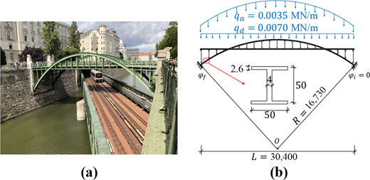
(a) Photo and (b) geometric dimensions of the investigated arch bridge “Zollamtssteg” in Vienna, Austria (length unit: mm)
(a) Photo and (b) geometric dimensions of the investigated arch bridge “Zollamtssteg” in Vienna, Austria (length unit: mm)
Herein, one half of the bridge, consisting of one arch, one half of the bridge deck, and one pair of hangers/columns, is investigated. The dead load, qd = 0.0070 MN/m, refers to one half of the bridge deck. It is carried by the arch via the hangers, above the bridge deck, and the columns, below the bridge deck.
The sensitivity of the load-carrying behavior of the arch with respect to the number of equally spaced hangers/columns, n, was investigated, considering dead load of the arch and the bridge deck. Dead load of the hangers/columns was not taken into account, because it is much smaller than that of the arches and the bridge deck. The sensitivity analysis followed an approach similar to the one described in Zhang et al. (2018). At first, classical structural analysis of the deck, representing a continuous beam with n intermediate supports (Figure 2), was carried out. The forces of the hangers/columns were equal to the support forces. Finally, structural analysis of the arch, subjected to n point loads, was accomplished by means of the transfer relations (1). n ranges from 1 to 30. Hence, altogether 30 analyses were performed. The maximum bending moments of the arch, , are determined (Figure 3). As the number of the hangers/columns n increases from 1 to 10, the maximum bending moment decreases by 60%. A further increase of n results in an insignificant decrease of the maximum bending moment of the arch. Therefore, with regards to the analyzed arch bridge, 10 equally spaced hangers/columns are sufficient for a good distribution of the deck weight.
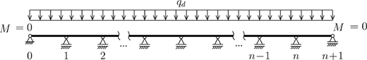
Sketch of the deck: statically indeterminate continuous beam with n intermediate supports
Sketch of the deck: statically indeterminate continuous beam with n intermediate supports
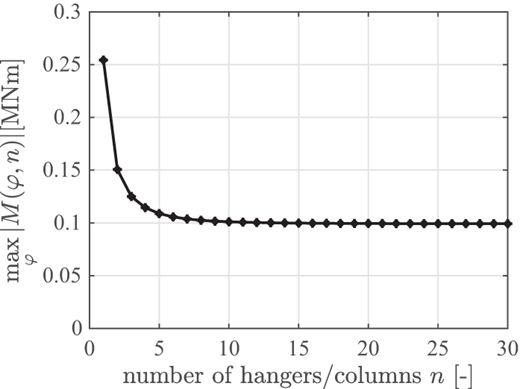
Sensitivity of the maximum bending moment of the arch with respect to the number of hangers/columns
Sensitivity of the maximum bending moment of the arch with respect to the number of hangers/columns
Knowledge of the internal forces allows for stress analysis. With the help of equations (4) and (5), the von Mises stresses are obtained from:
Increasing the number of the hangers/columns from 1 to 5, and further to 10 and 21, results in a decrease of the maximum von Mises stress from 36.98 MPa to 19.15 MPa, 18.23 MPa and 18.07 MPa (Figure 4). The maximum displacement decreases from 7.4 mm to 2.6 mm, as the number of the hangers/columns increases from 1 to 5. A further increase of this number, however, only results in an insignificant change of the maximum displacement.
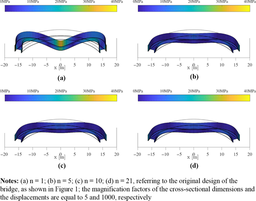
Distributions of the von Mises stresses in the deformed configuration of the investigated arches with different numbers of hangers/columns
Distributions of the von Mises stresses in the deformed configuration of the investigated arches with different numbers of hangers/columns
The transfer relations are appealing to structural analysis of arch bridges, because of the following reasons:
Compared to mesh-based numerical simulation methods, the transfer relations reduce the amount of preprocessing in the framework of sensitivity analysis of arch bridges with respect to number of hangers/columns. The former typically require re-meshing of the arch when either changing the number of hangers or the locations of their connection to the arch, because each of such connections requires node-to-node connectivity. However, the transfer relations allow to account for the forces and locations of hangers/columns by means of load integrals, i.e. in a straightforward manner. This advantage is non-trivial, because preprocessing (including mesh generation) generally dominates the time needed for performing structural analysis.
Compared to discretization-based numerical solutions, the transfer relations, representing analytical solutions, do not suffer from discretization errors. Therefore, there is no need for quantification of this error in form of a convergence study.
Transfer relations are computationally inexpensive, because the solution of a given problem only involves evaluations of the product of a 7 × 7 transfer matrix and a 7 × 1 vector.
4. Structural analysis of a vault element of a metro station
The metro station considered is the Wuzhong Road Metro Station in Shanghai, see the details described in Zhang et al. (2020). Its vault, which is part of the station, is a segment of a cylindrical shell. It consists of 56 identical arch elements, arranged in a parallel fashion along the axis of the vault. The width B, the span L and the radius R of the elements are equal to 2.95 m, 19.8 m and 15.1 m, respectively. The vault was constructed by a combined precast and in situ cast method (Zhang et al., 2020). Thus, a vault element consists of a precast part and an in situ cast part. The precast part serves as the permanent formwork of the in situ cast concrete, see Figure 5 for part of the permanent formwork. Each vault element consists of two precast arch segments. The shape of the cross-section of these segments is an upside-down π [Figure 6(a)]. The thickness of the flange amounts to 100 mm. The width and the height of the ribs are equal to 25 mm and 50 mm, respectively. The width B and the height H of the rectangular cross-section of the integral arch elements amounted to 2.95 m and 1.0 m, respectively. The strength class of the used concrete is C35. Its Young’s modulus is equal to 31.5 GPa.
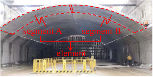
Photo of the precast part of the vault of the Wuzhong Road Metro Station in Shanghai, serving as a permanent formwork
Photo of the precast part of the vault of the Wuzhong Road Metro Station in Shanghai, serving as a permanent formwork
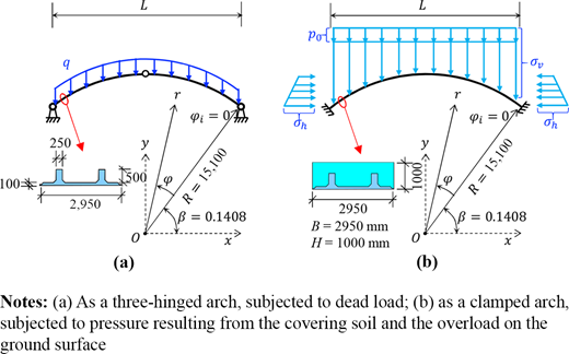
The loads depend on the construction program. The precast segments were produced in a factory. After curing, they were transported to the construction site. Two segments each are assembled to a three-hinged arch, serving as a permanent formwork. The arch carries the dead load of the integral arch, q = 0.059 MN/m [Figure 6(a)]. After hardening of the in situ cast concrete, the integral arch becomes a clamped arch, subjected to equivalent ground pressures in the vertical and the horizontal directions, denoted as σv and σh, respectively [Figure 6(b)]. These pressures are given as follows (Zhang et al., 2020):
where β denotes the inclination angle of the initial cross-section relative to the x-axis, hs stands for the height of the covering soil at the crown of the vault, p0 stands for the overload on the ground surface and γ and K denote the unit weight and the lateral pressure coefficient of the soil, respectively. As for the investigated vault element, β, hs, p0, γ and K are equal to 0.1408 rad, 2.65 m, 20 kPa, 20 kN/m3 and 0.65, respectively.
Two modes of structural analysis were carried out with the help of the transfer relations. The first one simulates the combined precast and in situ cast construction method. The results were obtained by superposition of results from structural analysis of the three-hinged arch, subjected to dead load, and results from structural analysis of the clamped arch, subjected to the ground pressure, see the magenta curves in Figure 7. The second mode simulates the conventional in-situ-cast construction method. The results were obtained from structural analysis of the clamped arch, subjected to both dead load and the ground pressure, see the green curves in Figure 7. The effect of the construction method on the deformed configuration and the distribution of the bending moments of the vault element is significant. This is underlined by the fact that the deflection at the crown of the vault element, constructed by the combined precast and in situ cast method, is by 308% larger than that obtained by the in situ cast method [Figure 7(a)], but that the maximum bending moment in case of the former is by 46% smaller than that in case of the latter, [Figure 7(b)]. However, the value of the deflection at the crown of the vault element, constructed by the combined precast and in situ cast method, is only 0.026% of the span of the vault. Hence, the percentage increase of this deflection compared to the one obtained by the in situ cast method is irrelevant. The effect of the construction method on the normal and the shear forces is insignificant [Figures 7(c) and 7(d)].
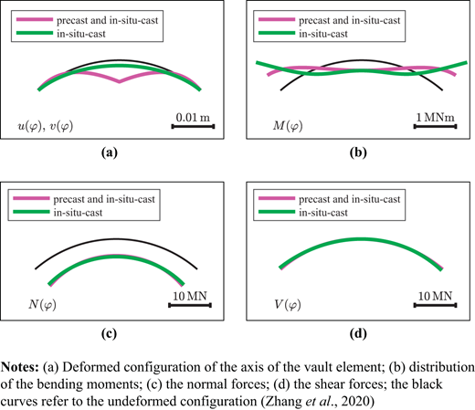
Analysis results for a vault element constructed by the combined precast and in situ cast method, see the magenta curves, and, alternatively, by the in situ cast method, see the green curves
Analysis results for a vault element constructed by the combined precast and in situ cast method, see the magenta curves, and, alternatively, by the in situ cast method, see the green curves
An advantage of using transfer relations for structural analysis of the vault element is the way of consideration of the boundary conditions. They are satisfied by means of determination of the six kinematic and static variables at the initial cross-section. The three boundary conditions at this cross-section directly provide the solutions for three of the six variables. The three boundary conditions at the final cross-section provide three linear equations for the remaining three kinematic and static variables at the initial cross-section. A change of the boundary conditions results only in a change of the six kinematic and static variables at the initial cross-section, whereas the transfer matrix remains unchanged. This is particularly useful for a comparative analysis of vault elements with different boundary conditions.
5. Hybrid structural analysis of a real-scale test of a segmental tunnel ring
The re-analyzed real-scale test of a segmental tunnel ring was carried out at Tongji University (Liu et al., 2016; Figure 8). The radius R of the centerline of the tested ring was equal to 2.925 m. The rings consisted of six reinforced concrete segments. Young’s modulus E, the uniaxial compressive strength fc, and the tensile strength ft of the concrete were determined from multiscale models (Königsberger et al., 2018; Hlobil, 2016), as 43.6 GPa, 62 MPa and 3.17 MPa, respectively. The width B and the height H of the cross-section of the segments amounted to 1.2 m and 35 cm, respectively. The ring was loaded all way up to its bearing capacity. This was done by means of three groups of altogether 24 equally spaced hydraulic jacks, acting on the outer surface of the ring. The experimental monitoring involved the jack forces and the displacement/rotation discontinuities, developing at the segment-to-segment joints, as well as the vertical and the horizontal convergences.
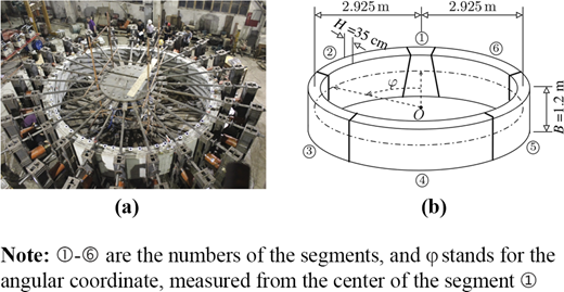
(a) Photo and (b) geometric dimensions of the analyzed segmental tunnel ring according to Liu et al. (2016) and Zhang et al. (2017), respectively
(a) Photo and (b) geometric dimensions of the analyzed segmental tunnel ring according to Liu et al. (2016) and Zhang et al. (2017), respectively
During the test, cracking of the reinforced concrete segments, a reduction of the initial contact area of the segment-to-segment joints, and crushing of concrete in compression at the joints was observed. Therefore, the analysis of the bearing capacity of the tested segmental tunnel ring requires consideration of the nonlinearities resulting from both cracking of the segments and the complex behavior of the joints, including segment-from-segment separation and the nonlinear behavior of the materials of the joints. Herein, a hybrid method (Zhang et al., 2017) was used for structural analysis of the tested ring. This way, the complex behavior of the joints was considered in a straightforward manner, because the measured relative rotations at the joints, together with the external loading, were used as input. Bending-induced tensile cracking of the segments requires the extension of the linear transfer relations to consideration of the nonlinearities resulting from such cracking.
The hybrid analysis consists of two load cases (Zhang et al., 2019a). This approach follows scientific work by Blom (2002) and by El Naggar and Hinchberger (2008). They assumed that the relative rotation angles at the joints result in rigid-body displacements of the segments. Load Case I refers to these rotations. They are estimated from monitored data, based on the Bernoulli–Euler hypothesis, and then post-processed such as to refer to rigid-body displacements of the segments, see Zhang et al. (2019a) for details. This post-processing is carried out with the help of transfer relations including the load integrals for the relative rotation angles at the joints. Based on the analysis of Load Case I, rigid-body displacements of the segments are obtained. Load Case II refers to the point loads, while the relative rotation angles are set equal to zero. In this case, the corresponding structural analysis is one of a closed ring without joints, subjected to point loads. To consider bending-induced tensile cracking of the six segments, they are subdivided into 34 elements. The length of the elements in the tangential direction is approximately equal to the distance of neighboring cracks. The elements contain a crack band in the middle and an undamaged zone on each one of the two sides. The extensional stiffness and the bending stiffness of the crack band is quantified by a multiscale model for tensile softening of concrete (Hlobil, 2016). Then, the effective bending and extensional stiffnesses of the damaged element are quantified, using the Voigt–Reuss–Hill estimate (Hill, 1952). These stiffnesses are constant within the elements. They are used for simulations of the segmental tunnel ring, based on the linear transfer relations. Superposition of the two load cases completes the nonlinear hybrid analysis of the segmental tunnel ring. This is admissible, even though the analysis of Load Case II is nonlinear, because Load Case I only results in rigid-body displacements and the equilibrium conditions of the structure are formulated in the undeformed configuration.
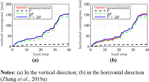
The model-predicted convergences are compared with corresponding experimental measurements (Figure 9). Their agreement underlines the usefulness of the chosen analysis approach. It is notable that rigid-body displacements of the segments (see the green curves in Figure 9) are responsible for approximately 95% of the convergences, whereas the deformations of the segments (see the black curves in Figure 9) are only responsible for the remaining 5%. Therefore, the relative rotation angles at the joints govern the convergences of the analyzed segmental tunnel ring.
The normal stresses of the concrete are evaluated from the obtained internal forces, the effective stiffnesses of the elements and the constitutive model of the concrete (Zhang et al., 2019a). Then, the level of loading of the concrete is quantified by the stress levels ζ, defined as (Hellmich et al., 2001):
where ω denotes the damage variable, which is equal to the crack density parameter by Budiansky and O’Connell (Budiansky and O’Connell, 1976). ζ = 1 indicates that concrete cracks in tension and ζ = –1 that it crushes in compression. When the bearing capacity was reached, ζ was equal to 1 at the inner surface in the crown and the bottom regions as well as at the outer surface in the two lateral regions, see Figure 10 for the distribution of the stress levels in the deformed configuration. However, the blue color, associated with ζ = –1, does not appear. Because the development of plastic hinges requires the compressive stress of concrete to reach the compressive strength, i.e. ζ = –1, there are no plastic hinges inside the segments. Further analysis of the joints has shown that the bearing capacity of the segmental tunnel ring is a consequence of the development of plastic hinges at the two top joints and the two lateral joints.
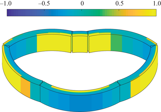
Distribution of the stress levels in the deformed configuration at the bearing capacity; the magnification factors of the cross-sectional dimensions and the displacements are 1 and 10, respectively
Distribution of the stress levels in the deformed configuration at the bearing capacity; the magnification factors of the cross-sectional dimensions and the displacements are 1 and 10, respectively
Herein, the relative rotation angles at the joints are post-processed such that they refer to a symmetric mode of rigid-body displacements of the segments. A generalized mode of rigid-body displacements was recently considered in Jiang et al. (2020). In addition, the described hybrid method of analysis of segmental tunnels requires measured relative rotations at the segment-to-segment interfaces. If such measured quantities are not available, it is necessary to resort to a classical mode of analysis of such tunnels. To this end, linear transfer relations are combined with a nonlinear interface law (Zhang et al., 2019b).
The hybrid approach eliminates the need to consider the interfacial nonlinearities and, thus, significantly simplifies structural analysis (Zhang et al., 2017). The transfer relations are very valuable for such hybrid structural analysis, because they consider, in a straightforward manner, the relative rotation angles at the joints. As for finite element methods, prescribing these relative rotations, however, is a challenging task.
6. Conclusions
Transfer relations, representing analytical solutions of the linear theory of circular arches, were used for computer-aided engineering analysis of an arch bridge, a vault of a metro station, and a segmental tunnel ring. The following conclusions are drawn from these three examples:
Increasing the number of hangers/columns of arch bridges results in less concentrated loading of the arch, rendering a reduction of the maximum bending moment of the arch. For the investigated arch bridge, ten equally spaced hangers/columns are sufficient for a good distribution of the deck weight. Further increase of this number results in an insignificant reduction of the bending moments.
As regards the vault element of the metro station at Wuzhong Road, Shanghai, a combined precast and in situ cast method of construction results in a decrease of the maximum bending moment by 46%, compared to the one obtained by the conventional in situ cast method.
The hybrid method allows for re-analysis of the bearing capacity of the tested segmental tunnel ring. The analysis results show that the local behavior of the joints governs both the structural convergences and the bearing capacity.
It is interesting to compare the used approach for structural analysis based on transfer relations to the alternative and very popular approach of numerical analysis based on the finite element method (FEM) for curved beams. Notably, results from FE simulations converge, with increasing discretization efforts (i.e. with increasing fineness of the used FE meshes), toward analytical solutions. Thus, every application of the FEM requires a convergence analysis, involving at least one coarser FE mesh and typically two consistently refined FE meshes. Thereby, mesh generation takes a significant amount of time, particularly so in the presently discussed context of linear structural analysis. This underlines the usefulness of the transfer relations, because they provide direct access to analytical solutions of the linear theory of thin circular arches. The resulting advantages, demonstrated by the three presented examples, are summarized as follows:
Transfer relations reduce the complexity of structural analysis of circular arches to that of structural systems consisting of straight beams. These relations are particularly attractive for sensitivity analysis regarding, e.g. the number of hangers/columns of arch bridges, because they can be easily specialized for different numbers of these structural elements.
Transfer relations are beneficial to a comparative analysis of vault elements with different boundary conditions, to which they can be easily specialized by means of the integration constants.
Transfer relations are very valuable for hybrid structural analysis of segmental tunnel rings, because they can consider, in a straightforward manner, the relative rotation angles at the joints by means of load integrals.
Financial support by the Austrian Science Fund (FWF), provided for the project P 281 31-N32 “Bridging the Gap by Means of Multiscale Structural Analyses”, is gratefully acknowledged. In addition, the first author is indebted to the National Natural Science Foundation of China (Grant No. 51908424), the Shanghai Pujiang Program (Grant No. 19PJ1409700) and to the Austrian Federal Ministry of Education, Science and Research (BMBWF) (Grant No. ICM-2019-14045) for financial support of this work. The second author is also indebted to the National Natural Science Foundation of China (Grant No. 51578409), for financial support of this work.
