This paper studies the response of building integrated photovoltaic (BIPV) floor tiles under normal thermo-mechanical conditions and superimposed short-term sustained loads. While the thin glass covers are in general minimally affected by ordinary thermal effects, the typical BIPV section suffers for possible loss of mechanical capacity, due to the sensitivity of the constituent materials, especially the encapsulant. Also, the features of fixing systems have further influence on the mechanical response.
3D numerical models are inspired from real BIPV tiles and used to investigate the coupled thermo-mechanical performance of BIPV tiles under ordinary conditions. The effects of temperature variations are highlighted in terms of deflection, stress and bending stiffness.
Key mechanical performance indicators of typical use for laminated glass are critically discussed for the examined BIPV floor tiles. As shown, the serviceability deflection check of BIPV tiles is a key parameter of their performance assessment, which implicitly suffers from the progressive modification of the bending stiffness with increasing temperature.
Structural glass members are usually designed as load-bearing elements in terms of serviceability deflection and ultimate tensile stress verifications. One of the most influencing parameters in their mechanical analysis is represented by the shear flexibility of the interlayer in use to bond the glass panels. This aspect is even more pronounced for BIPV solutions, where both the glass covers and the encapsulant are subjected to non-uniform temperature scenarios due to ordinary heating, whilst their load-bearing role and mechanical capacity should be in any case preserved. This study shows the key role of thermo-mechanical considerations for similar systems, even under ordinary operational conditions.
1. Introduction
Building integrated photovoltaic (BIPV) solutions are increasingly used in constructions (Batista et al., 2025). Modular units with glass-glass covers can be adapted to many design needs (Yin et al., 2021; Rosa, 2020), such as balustrades, roofs (Teka et al., 2023; Del Pero et al., 2024), facades (Corrao, 2018; Sureshkumar Jayakumari et al., 2024; Bedon et al., 2019; Karunyasopon et al., 2024), prefabricated walls (Chen et al., 2003), floors (Eder et al., 2019), etc.
BIPV floor tiles, in particular, can integrate the principles of renewable energy generation with architectural needs for innovative pedestrian systems, transforming conventional walkways and floor solutions into interactive power-generating surfaces. Beyond the scope of green energy generation and sustainability, there are however many multi-functional aspects that should be properly taken into account for the optimal design and performance assessment of BIPV floors, especially to satisfy structural and mechanical demands (Zhang et al., 2018; Meng et al., 2021; Misara and Pornnimit, 2011; Youssef et al., 2016). Mechanical and thermo-physical modifications that take place in the constituent components are in fact implicitly associated to additional effects for the load-bearing components (Bedon et al., 2019), and thus for the assessment of the BIPV performance. As such, even complex thermal and mechanical phenomena could interact with the energy generation process. Dedicated standards are available for certification and testing (IEC 61215–1; IEC 61730–2; IEC 63092–2), but even more studies are required.
In this paper, attention is given to the mechanical analysis of BIPV floor tiles with glass-glass covers and mechanical point-supports to study their structural performance under short-term sustained loads in more depth (i.e. accidental 30-second pedestrian load). The study takes inspiration from commercially available BIPV floor tiles, and its advantage comes from thermo-mechanical FE numerical modelling tools that are used for their analysis. A primary focus is given to the performance assessment of the thin glass covers and to the typical serviceability demands that are expected for load-bearing pedestrian components made of glass (CNR-DT210/2013Feldmann et al., 2023; CNR-DT210/2013). Glass itself is known as a brittle-in-tension construction material and to pose major challenges for structural design in terms of verification of tensile stress peaks (CNR-DT210/2013Feldmann et al., 2023; CNR-DT210/2013; Belis et al., 2026) and post-fracture residual performance (Bedon et al., 2025a, b). Stress peaks can particularly affect the glass section in the region of holes or point-fixings. Besides, the serviceability verification of deflections in presence of ordinary design loads is commonly expected to represent the governing design check especially for large-size and slender or fairly restrained glass members (CNR-DT210/2013; Feldmann et al., 2023), such as facade panels or balustrades. For pedestrian systems, finally, no specific standard requirements exist in terms of vibrations, and the definition of specific comfort limits for glass structures is still and open question (Bedon and Fasan, 2019).
In this paper, a numerical study is carried out to study the structural performance of modular BIPV floor tiles, showing that relatively squat and rigid BIPV tiles can severely suffer for uncomfortable deflections, rather than high tensile stress peaks.
For comparative purposes, the deflection limit values for the serviceability check are taken from (CNR-DT210/2013). More complex mechanical model to account for human-structure interaction phenomena and to elaborate specific comfort perception limits are disregarded for the scope of this study (Bedon and Fasan, 2019; Hassen et al., 2024).
As shown, the out-of-plane bending response of a BIPV tile can be fairly captured by simplified mechanical models based on the consolidated effective thickness concept, which are of typical use for 2-ply glass sections. Also, the stress distribution in the glass covers largely differs from a BIPV tile at ambient temperature. For the examined configuration, the deflection analysis is shown however to represent the governing parameter for the performance assessment, which is rather unusual for a rigid member. Finally, the fundamental vibration frequency can represent a useful monitoring parameter for degradation analysis.
2. Research assumptions
2.1 Scope and limits
The present study investigates the response of BIPV floor tiles under normal operating thermal conditions, which means that the maximum expected temperatures are in the order of ≈90 °C. Such an assumption largely differs from the BIPV performance assessment under extreme scenarios, such as fire (Bedon et al., 2025a, b), but requires in any case specific methodologies of analysis and assessment.
In this regard, it is important to remark that this study is limited to ordinary conditions, while even more severe configurations should be separately investigated and addressed, for enhanced safety and durability optimization purposes. For example, the present outcomes do not apply and cannot be extended to extreme and accidental temperature scenarios like hot spot (Dhimish et al., 2018); long-term mechanical loads associated to creep phenomena in the interlayer (Bosco et al., 2020; Dusane et al., 2023); possible debonding and loss of adhesion (Bedon and Massi Pavan, 2024); variable installation features or ambient conditions (Chiteka et al., 2022; Keddouda et al., 2024).
Whilst ordinary conditions are relatively simple, they are sufficiently complex to require careful consideration. Structurally speaking, due to the interconnected thermal and mechanical phenomena, the operating BIPV tile can be fairly investigated as a 2-ply glass section. For the selected thermal scenario, glass material does not suffer in fact for mechanical modifications and could be treated as a linear elastic. The consolidated, simplified mechanical calculations based on the equivalent thickness concept (Galuppi and Royer-Carfagni, 2012) are robust and efficient for different mechanical loading and boundary conditions (see also Section 4). Their key feature is the use of an equivalent secant modulus of elasticity for the encapsulant, to capture a specific temperature and time loading scenario. Besides, they cannot capture the effects due to progressive, non-uniform thermal scenarios. The thermal stresses in simple glass elements could be eventually addressed by means of additional consolidated analytical closed-form formulations (Foraboschi, 2017; Galuppi et al., 2024). Besides, the layout specification and temperature-dependent response of BIPVs would make again challenging their structural analysis.
2.2 Methods and findings
This study poses the attention on BIPV tiles (0.5 m × 0.5 m their size, with 6 mm thick glass covers) in ordinary conditions, focusing on the typical mechanical phenomena and on their performance assessment, based on literature indicators.
The mechanical performance (i.e. stress and deflection indicators for the load-bearing glass covers) is assessed based on performance indicators that are of common use for the structural analysis of 2-ply laminated glass members (CNR-DT210/2013). In particular, to further emphasize the role of ordinary temperature variations, the effect of a superimposed short-term distributed load is taken into account, as in use for the mechanical design of pedestrian systems (with q = 3 kN/m2 the magnitude of the distributed pressure, corresponding to an equivalent 30-second pedestrian load).
The final goal is to guide experts towards a more in-depth analysis of ordinary operating conditions, promoting the use of complex modelling strategies to optimize design, safety and maintenance of BIPV tiles.
To this aim, the reference FE model described in ABAQUS to represent the selected BIPV tile is first thermally validated towards experimental temperature measurements that are collected from a set of BIPV floor tile samples. Temperature measurements are particularly used to assess the thermal transmission through the thickness of the composite BIPV section, considering the uncertainties of model calibration.
It is emphasized that:
Whilst moderate temperatures are achieved in the BIPV components, the modification of common material properties with temperature – as well as the non-uniform temperature increase in the BIPV section – should be properly taken into account for the cross-section detailing.
The simplified estimates “in cold conditions” (i.e. disregarding the temperature sensitivity of materials and the non-uniform thermal exposure) roughly capture the deflection and stress trends for the examined BIPV tiles, which indeed suffer for a marked stiffness relaxation of the encapsulant and a progressive weakening effect for the composite glass-glass load-bearing section.
The role of mechanical restraints has major effects, for the selected configurations.
As a consequence, even the glass covers that are still elastic, the global out-of-plane bending stiffness decreases and accordingly the deflection and stress demand increase.
Finally, whilst the limited size of the examined BIPV tiles could suggests a certain out-of-plane rigidity and high stiffness, it is shown that the combined features of the BIPV composition and the use of discrete point-supports result some important mechanical effects that can be efficiently quantified with the fundamental vibration frequency. First, the vibration frequency could represent a valid practical tool. Secondly, thus parameter could be used to improve the pedestrian comfort (Bedon and Fasan, 2019).
3. Examined BIPV system
For the present study, at the time of the experiments, a commercial BIPV tile was chosen as an example of typical tile. Compared to other commercial products, minor variations could take the form of different size, cross-section detailing or fixing detailing. The herein described geometrical features were taken into account to inspire the model description and perform parametric calculations, based on literature material properties.
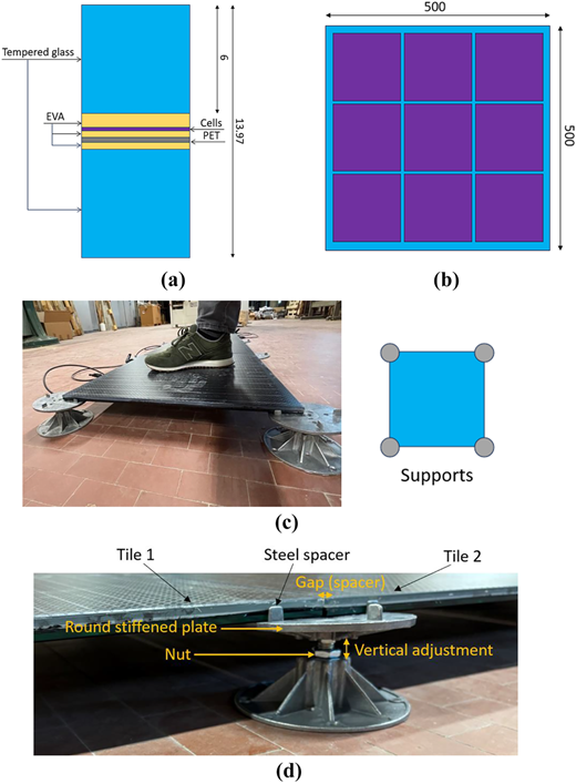
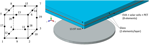
More in detail, the reference system consists of a glass-glass BIPV flooring solution, which takes the form of a square modular unit with size 0.5 m × 0.5 m. The resisting cross-section has a total thickness of 13.97 mm, and includes a 6 mm thick (anti-slip) glass cover on top, EVA encapsulants (1.52 mm in total thickness), embedded solar cells (0.2 mm thick) and a 0.25 mm thick PET layer. Finally, the back cover is composed of a 6 mm thick glass layer. The solar cells have square shape, with edge dimensions of 156.75 mm (3 × 3 matrix). Figure 1 (a) shows the cross-section composition and the geometrical layout, while Figure 1(b) schematizes the cell arrangement (front view). Tempered glass was used for the top and bottom covers.
Round mechanical point-supports are used at the corners of the modular unit, see Figure 1(c) and (d). This solution provides support to glass by contact only, without the use of additional metal fasteners and can be adjusted to fit the desired height from the ground, by tightening of the nut of its bolted connection (Figure 1 (d)). Possible relative rotations of the top round stiffened plate are disabled. Once the BIPV floor tiles are installed and adjusted in their final position (with a maximum of four tiles for each fixing system), these devices can be assimilated to rigid discrete supports for the glass covers in contact. Such a technical detailing allows to create large glazed surfaces by installing a matrix of adjacent BIPV modules. The direct contact along the edges of glass is avoided by four small spacers that are interposed between the BIPV tiles (Figure 1 (d)).
4. Analytical mechanical model
4.1 Effective thickness
The structural analysis of BIPV systems under sustained loads has been investigated by many researchers, such as (Teka et al., 2023), where the effects of different mechanical restraints have been taken into account in terms of expected deflection and glass thickness optimization.
Considering the BIPV module as a 2-ply laminated glass section, analytical mechanical analysis of the reference floor tile can be also carried out – under simplified assumptions in cold conditions – by checking the serviceability deflection (and ultimate stress) demand/capacity ratio of the glass covers. In order to take into account equivalent material properties for the loading configuration of interest (CNR-DT 210/2013), the most important tasks regard the description of the mechanical restraints, the cross-section schematization and the material characterization (especially for the EVA encapsulant).
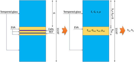
In this regard, the practical concept of effective thickness for the glass covers can be recalled from the literature and used to preliminary assess the mechanical performance of the BIPV system. According to (CNR-DT 210/2013; Galuppi and Royer-Carfagni, 2012) the Sandwich section can be preliminary reduced to a 2-ply laminated glass plate, by disregarding the solar cells (as well as other electrical components), see Figure 2.
It is thus assumed that the glass covers have thickness h1 = h2 (E the modulus of elasticity of glass and ν the Poisson's ratio), and the encapsulant has a total thickness hint (with Gint the equivalent shear modulus). The effective thickness for deflection and stress analysis can be thus respectively calculated as (Galuppi and Royer-Carfagni, 2012):
and
with:
The coupling coefficient, which assumes the limit values of 0 and 1 for the “layered” (i.e. weak shear bond between the glass covers) and “monolithic” (i.e. rigid bond) configurations respectively.
Moreover, in Eqs (1)-(3):
In Eq. (3), finally, Ψ is a coefficient able to account for the actual aspect ratio and mechanical loading/boundary configuration for the 2-ply section. Assuming that the BIPV tile is subjected to a uniformly distributed load, and considering that the reference tile has square shape with edge 0.5 m, according to (Galuppi and Royer-Carfagni, 2012) it is assumed that Ψ = 45.601 × 10⁻⁶ mm-2.
4.2 Mechanical performance indicators
Structural glass components are commonly verified in terms of deflection and stress parameters (CNR-DT 210/2013; Feldmann et al., 2023). The deflection limit for a BIPV tile according to Figure 1 considering the load-bearing role of the glass covers – can be assessed based on (CNR-DT 210/2013), and the proposed performance indicators that are recommended for the design of structural glass elements and systems.
More in detail, following (CNR-DT 210/2013), the reference deflection value wlim for a point-supported glass panel can be defined as the minimum between 1/100 of the span and 50 mm. For the presently examined BIPV tiles, this limitation results in wlim = 4.4 mm. However, the examined BIPV tiles are used for pedestrian surfaces, which means that a more conservative deflection limit could be also taken into account from (CNR-DT 210/2013), by referring to specific floor restrictions. In this last case, it is required to calculate wlim as the minimum between 5 mm or 1/500 the distance of supports, which means wlim = 0.88 mm for the present study. Such a rigid deflection limitation derives from the need of avoiding large deflections and possible discomfort for pedestrians under normal serviceability conditions (CNR-DT 210/2013; Feldmann et al., 2023; Bedon and Fasan, 2019).
Similarly, the ultimate tensile stress analysis should prevent that the maximum stress peaks in the glass covers could exceed the material strength (CNR-DT 210/2013; Feldmann et al., 2023). The use of fully tempered glass ensures higher resistance and improved capacity against possible thermal shock (Bedon et al., 2025a, b; Galuppi et al., 2024), especially in comparison to float glass (Wang et al., 2014). The material tensile strength has a characteristic value of 120 MPa (EN 572–1). Besides, floors and pedestrian systems are usually recommended to include a minimum of three glass layers in the resisting section, for safety and redundancy needs (CNR-DT 210/2013; Feldmann et al., 2023). The post-cracked stress analysis is in fact mandatory for structural systems made of glass (CNR-DT 210/2013; Feldmann et al., 2023), and many literature studies emphasized the effects of unfavourable operational conditions on structural glass pedestrian systems (Bedon and Fasan, 2019). Also, possible spontaneous failure mechanisms should be considered (Callewaert et al., 2011).
Another key performance indicator for BIPV pedestrian tiles can be represented by their fundamental vibration frequency. To avoid discomfort and annoyance for pedestrians, a flooring system and component should be able to offer a minimum vibration frequency of 8 Hz (Bedon and Fasan, 2019). Whilst small BIPV tiles can be expected to have higher vibration frequency, as shown in this paper, its variation and sensitivity to temperature should be properly assessed.
4.3 Preliminary analytical results
In cold conditions, the analytical modelling assumptions summarized in Section 4.1 can provide sufficient feedback for a preliminary mechanical analysis of deflection (and stress) demands, which can support the optimal and safe dimensioning of the glass covers against the imposed mechanical loads.
Whilst this approach fully disregards any superimposed thermal action, it can help to derive some feedback about the role of BIPV components and their sensitivity in terms of mechanical performance.
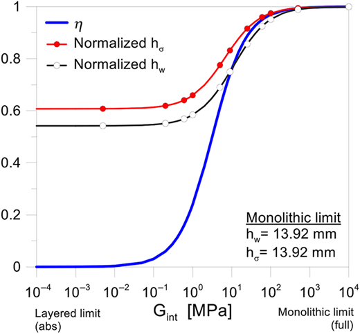
In this regard, Figure 3 shows the modification of the reference parameters previously defined in Section 4.1, as a function of the shear modulus of the encapsulant, Gint. The effective thickness values for deflection and stress analysis are proposed in normalized form, as a function of their maximum value at the “monolithic” limit. The weakest is the shear bond for the glass covers and the smallest is the bonding coefficient η, and consequently the calculated effective thicknesses, which progressively decreases to the “layered” bound.
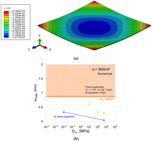
Based on the effective thickness values of Figure 3, a dedicated FE model was developed to estimate the expected deflection under imposed mechanical loads, by taking into account the actual point-supported restraint configuration for the tile (Figure 4 (a)).
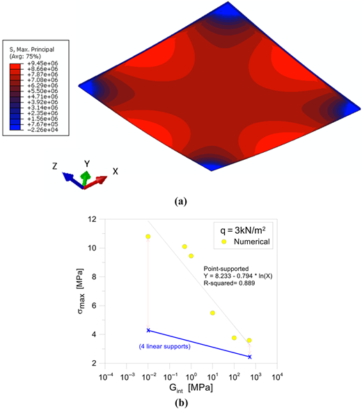
As far as the shear bonding of the encapsulant decreases, see Figure 4 (b), the BIPV tile loses significant bending stiffness and is subjected to increasing deflections for a given constant mechanical load. Figure 4 (b), more specifically, shows the example for the BIPV tile under a uniformly distributed, accidental load q = 3 kN/m2 (30-seconds its conventional duration, according to (CNR-DT 210/2013)).
The mechanical performance is in fact assessed by considering the short-term response of the BIPV system, i.e. as in presence of an accidental load q which represents the prevailing loading contribution. This assumption strongly simplifies the mechanical analysis of the laminated glass section. Additional viscoelastic phenomena that typically affect the shear performance of the encapsulants in use can be in fact disregarded (CNR-DT 210/2013; Feldman et al., 2023; Galuppi and Royer-Carfagni, 2012). In other words, any modification in the mechanical properties of the materials (particularly the EVA layer) can be associated to temperature variations only, rather than a combined effect of loading time and temperature (CNR-DT 210/2013). Also, such an assumption well agrees with the features of the pedestrian load that is taken into account for the analysis. The numerical results are compared as a function of Gint, and towards the deflection limit for a flooring system, based on (CNR-DT 210/2013). Notably, the expected deflection for the same BIPV tile with four linearly supported edges (4L) would be in the order of wmax,4L = 0.36 mm with weak shear bond (Gint = 0.001 MPa), which means ˜ 4.7 times smaller than the solution with four point-supports at the corners, as for the present study (see Figure 4 (b)).
Also, the estimates from the stress analysis are those of a typical monolithic glass plate in cold conditions, with the assigned mechanical loads and point-supports, see Figure 5(a) and (b). The principal stress peaks can be detected in Figure 5 at the mid-span section of the edges in tension, with up to ≈9–10 MPa in presence of a weak encapsulant (Gint = 0.001 MPa). The corresponding stress peak with the 4L setup is ≈ two times smaller, and associated to a rather different distribution of stress peaks compared to Figure 5 (a).
5. Temperature analysis under ordinary operational conditions
5.1 Experimental temperature measurements
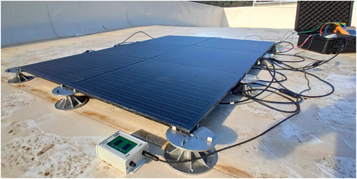
The first numerical check of thermal calibration was carried out with the support of on-site experiments, in order to assess the typical temperature range for the examined BIPV samples under ordinary operational conditions and the capacity of the reference FE model to capture the thermal evolution in the thickness of the BIPV section. To this aim, the electrical specifications of the PV modules tiles are described in Table 1. The experimental analysis was performed in November 2024 in Trieste (Italy), on a set of 6 modular units (2 strings of 3 series BIPV module tiles).
The specimens were positioned on the top roof of one of the campus buildings, with maximum exposure to solar radiation (Figure 6). The BIPV modules were exposed to sun radiation for a time interval of ≈3 h, starting from 10.30 a.m.
The instrumentation consisted of an HT I-V500 W IV curve tracer used in combination with a solarimeter with reference cell and a contact temperature probe (PT1000) for measuring the module surface temperature. The I-V500 W allows the acquisition of complete I-V characteristics on individual modules or short strings in the field and, in the configuration adopted, simultaneously records the irradiance of the plane of the array and module temperature to associate each electrical scan with the environmental conditions.
Irradiance was measured using the HT304 N reference cell (50–1400 W∙m–2, ±3% accuracy), mounted coplanar with the BIPV tiles in the same plane as the array. The module temperature was recorded by placing the PT300 N probe (−50 °C ÷ 105 °C) in the centre of the unexposed (bottom) BIPV glass cover, using an adhesive tape to ensure good thermal contact. The temperature and irradiance values reported in this paper are derived from a larger on-site campaign, in which the electrical quantities and full I-V curves of the BIPV tiles were collected for future works related to thermo-electrical modelling.
5.2 Temperature-dependent numerical model
A thermal FE numerical model was first developed to track and capture the temperature field of the reference experimental scenario. Each BIPV constituent layer and component was numerically reproduced in ABAQUS (Simulia, 2025), as an independent part. The bonding of adjacent layers was accounted via rigid “tie” surface constraints. The reference simulations included a first “heat transfer” transient analysis, to apply the thermal boundaries, and study the temperature distribution in the BIPV components. Following a preliminary sensitivity study and literature experiences (Machina et al., 2012; Louter et al., 2021; Perkovic et al., 2025; Bedon and Wang, 2025), a refined mesh pattern was taken into account, based on the use of 20-node heat transfer elements (DC3D20 type). DC3D20 bricks are fully integrated, 3D solid, 20-node quadratic isoparametric elements with 3 × 3 × 3 integration points (Figure 7). Their key feature is that they have only one active degree of freedom (DOF 11) at each node, corresponding to the nodal temperature.
By considering the geometrical features of the selected BIPV composition and layout, according to Figure 1 (a), the reference FE assembly included DC3D20 brick elements for all the sample components, namely: the top/bottom glass covers, the EVA encapsulant, the PET layer and the embedded solar cells, as well as the steel point-fixings. In this last case, more in detail, the top round stiffened plate of Figure 1 (d) was geometrically simplified with a circular steel plate, which was rigidly fixed to ground. As shown in Figure 7, the contact of the bottom glass cover and the steel plate was limited to one-fourth the top circular surface of steel, according to the geometry reported in Figure 1. For the heat transfer analysis, a rigid “tie” constraint was interposed between glass and steel.
Overall, the accuracy of temperature predictions was ensured by defining two brick elements in the thickness of each glass cover and eight elements in the thickness of the encapsulant/cells. The final choice of such a mesh schematization (with 10 mm the edge size of elements) resulted in ≈25,000 elements and ≈150,000 DOFs for the heat transfer step. The model robustness is also discussed in Section 5.3. The heat transfer temperature-time estimates were used both for temperature comparisons with the experimental measurements and as thermal boundaries for the associated mechanical step (Louter et al., 2021; Perkovic et al., 2025; Bedon and Wang, 2025).
Following the heat transfer thermal step, the reference FE model was in fact adapted for introducing the predicted thermal effects in the associated mechanical step, by combining them with the 30-seconds superimposed mechanical load q. This means that the DC3D20 heat transfer elements were replaced by 20-node brick elements with quadratic interpolation of displacements (C3D20 type), having three translational DOFs for each node (i.e. 60 DOFs for each brick element), by keeping the same mesh pattern and node/element numbering. Considering the different element type, the total number of solid elements for the mechanical step still resulted in ≈25,000 like for the heat transfer step, while the number of DOFs increased three times, up to ≈450,000.
The mixed effect of time-varying temperatures and superimposed short-term mechanical loads was considered by means of a coupling solving strategy, in which the nodal temperatures at each time instant of the thermal analysis were imported from the heat transfer step and transferred to the corresponding nodes in the mechanical step (Louter et al., 2021; Perkovic et al., 2025; Bedon and Wang, 2025). The mechanical load q was uniformly distributed on the top surface of glass. Finally, a surface-to-surface contact interaction was interposed between the steel round plate and the corner of glass, to reproduce the real mechanical contact. To this aim, a hard contact behaviour was considered in the normal direction, in order to account for the possible separation in tension (i.e. during bending). At the same time, the glass-to-steel static friction coefficient was set in 0.3.
Considering that short-term, 30-seconds mechanical loads were only examined in the present study (as being well representative of a pedestrian moving load on tiles), possible viscoelastic and creep phenomena in the EVA encapsulant were disregarded (Belis et al., 2026), and the progressive degradation of the material was associated to the increasing temperature only. Notably, a similar modelling strategy should be further elaborated before it could be applied to different scenarios and configurations, where the effect of long-term mechanical loads or even variable installation and ambient conditions could be relevant (Bosco et al., 2020; Dusane et al., 2023; Bedon and Massi Pavan, 2024; Chiteka et al., 2022; Keddouda et al., 2024).
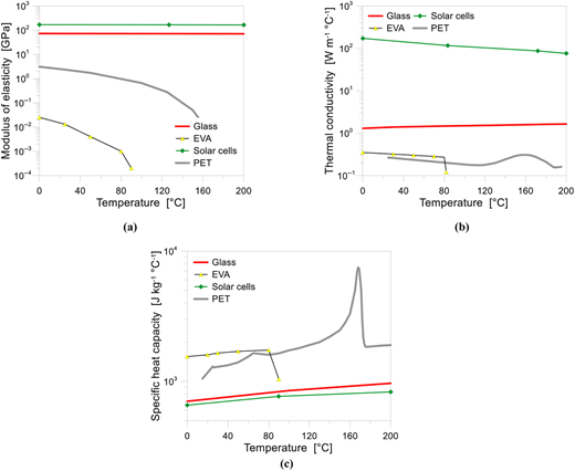
The input properties for all the relevant materials composing the examined BIPV tile (glass, EVA, solar cells, PET), as well as their sensitivity to temperature variations, are reported in Figure 8 and were taken into account from previous literature applications on thermo-mechanical performance assessment of BIPVs, see (Bedon et al., 2025a, b; Bedon and Wang, 2025). In this regard, it is important to remind that the presently examined thermal range was limited to temperatures lower than 100 °C, which are associated to totally different phenomena compared to fire (Louter et al., 2021; Perkovic et al., 2025; Bedon et al., 2025a, b; Bedon and Wang, 2025). For clarity of presentation, the temperature-dependent material properties in Figure 8 are in any case extended to a maximum of 200 °C.
More in detail, glass was numerically described in the form of a temperature-dependent linear elastic material, similar to (Bedon et al., 2025a, b; Bedon and Wang, 2025). Notably, its modulus of elasticity progressively decreases with the increasing temperature, but its sensitivity to the examined temperature range was rather small (Figure 8 (a)). In parallel, its thermal conductivity and specific heat capacity were described according to Figure 8 (b) and (c).
A special attention was given to the EVA encapsulant, which is well-known characterized by viscoelastic and creep phenomena, as it happens for the common interlayer materials (Belis et al., 2026). In this study, the possible material degradation was associated with the increasing temperature only. For the BIPV tiles, a short-term mechanical load (i.e. pedestrian moving load) was in fact taken into account. According to (Hana et al., 2019; Elkilani et al., 2024; Belis et al., 2026) and others, short-term loads are associated to a rather stiff and instantaneous response of EVA interlayer materials, which does not induce viscoelastic effects. In other words, the temperature-sensitivity was detected in this study as the governing influencing parameter for the purpose of the present investigation.
In these hypotheses, the EVA encapsulant was modelled with a temperature-dependent linear elastic law. More in detail, due to the lack of specific experimental material characterizations, the temperature-dependent modulus of elasticity of the EVA encapsulant was described according to Beinert et al. (2017), while the thermal conductivity was estimated based on Jia and Zhang (2022). The specific heat capacity was finally defined as reported in Figure 8 (c).
For the description of the solar cells, an elastic-plastic material was taken into account, and its input properties were derived from (Desai, 1985; Morris and Hust, 1961). The four-point bending experiments and simulations based on beam theory assumed in Bedon and Wang (2025) provided an average modulus of elasticity equal to 166 GPa at room temperature, which well agrees with the additional three-point bending tests performed in (Bedon et al., 2025a, b) at room temperature. To account for the effect of thermal exposure, its temperature-dependency was described based on Liu (2021). The interposed PET layer was finally characterized as reported in Figure 8, based on the material properties adopted for modelling in Bedon and Wang (2025).
To implement the reference FE model, care was spent for the preliminary description of thermal exposure and contributions in the BIPV components (Bedon et al., 2025a, b; Bedon and Wang, 2025). According to literature, it was assumed that only the top glass and the solar cells could absorb part of the incident solar irradiation GPOA. The internal heat generation due to absorption of the top glass cover is in fact given by:
where Aglass and Vglass are the exposed surface and volume of the top glass cover, while αglass = 0.005 is the effective absorptivity (Limane et al., 2023). To account for the amount of solar radiation that is transformed to internal heat, the approach by (Zhou et al., 2017; Siddiqui et al., 2012) was taken into account:
where ηc represents the temperature-dependent electrical conversion efficiency of the solar cells (up to 24% for more recent products). In general, ηc can be expressed as (Evans, 1981):
In Eq. (11), Tref is the electrical efficiency at standard test condition; βref [1/°C] is the solar radiation coefficient; Tcell and Tref = 25 °C are the cell operating temperature and the reference temperature respectively. This linear relation accounts for the reduction in the conversion efficiency with the increasing temperature. As decreases, a larger fraction of the absorbed solar radiation is converted into heat, resulting in an increase in the term. This introduces a thermo-electrical coupling in the model, affecting the temperature and, consequently, the thermally induced stresses.
Moreover, in Eq. (10), Acell and Vcell denote the exposed area and the corresponding volume of material for the solar cells, while αcell = 0.9 is the absorptivity of sunlight. Finally:
where = 0.93 represents the effective absorptance of solar cells and τ = 0.92 is the transmissivity of the top glass cover (Evans, 1981).
5.3 Model robustness and mesh sensitivity
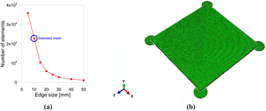
In terms of temperature distribution in the BIPV components, as also expected, a primary effect was found to derive from the mesh features. This was also associated to additional sensitivity of the corresponding mechanical analysis. The adopted regular mesh pattern was in fact chosen to capture local thermal phenomena but preserving the computational cost of simulations, as well as provide stable results in terms of stress and deflection estimates. This means that a double sensitivity study was carried out to assess (1) the thermal and (2) the mechanical response (at ambient temperature) of the examined BIPV tile. Overall, the size of mesh elements was varied between 5 mm and 50 mm (with intermediate steps of 10, 15, 20, 25, 30 and 40 mm, see Figure 9(a) and (b)), and the final mesh pattern with 10 mm edge size was selected from the comparison of preliminary results.
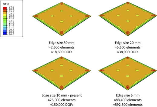
For the temperature prediction, see Figure 10, no relevant variations were noted in terms of thermal estimates in the central region of the tile. The predicted temperature for the experimental control point (i.e. centre of the bottom glass cover, see Section 5.1) was in fact associated to minimum effects due to mesh, quantified in a decimal part only of Celsius degree. Besides, the mesh pattern mostly affected the local thermal estimates (i.e. at the corners of the BIPV tile) and thus the corresponding mechanical results. Figure 10 shows an example of selected contour plots of temperatures in the top glass cover. Minor scatter in the temperature distribution at the corners can be noted only when reducing the edge size of brick elements to 20 mm, or even less.
The final mesh pattern was set in a 10 mm edge size, in order to achieve appropriate consistency for both thermal and mechanical results. The choice was supported not only by thermal estimates as in Figure 10 but also by preliminary mechanical predictions for the same BIPV tile. In doing so, an additional influencing parameter was represented by the total CPU time required by each simulation.
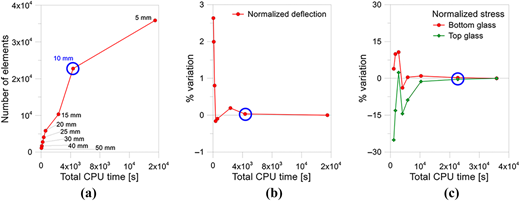
In this regard, Figure 11 reports some selected results from the mechanical analysis of the BIPV tile subjected to the assigned distributed load q. Figure 11 (a) shows the number of elements and the total CPU time associated to each mesh configuration, with evidence (blue circle) of the adopted model for the present study. The BIPV tile was initially investigated at ambient temperature, to emphasize the effects of mesh features only. More in detail, a major sensitivity to mesh features was observed for the local stress estimates in the glass covers. In terms of mechanical response of the examined BIPV tile, Figure 11 (b) shows in fact the trend of the normalized deflection, when changing the mesh size. The maximum deflection scatter – compared to the more refined mesh estimates – was calculated in about ≈3%. Less than 0.2% scatter was obtained for the mesh size of 25 mm. At the same time, Figure 11 (c) shows the variation of the normalized stress peak in glass (top and bottom covers), by changing the mesh size. In this case, the calculated scatter was estimated in about ≈1% for the 15 mm pattern, but drastically increased by increasing the edge size to 25 mm or even more. In both Figure 11 (b) and (c) it can be thus seen that the adopted mesh pattern was found able to provide stable results, as well as a good compromise between accuracy and computational cost.
6. Numerical results and discussion
6.1 Temperature estimation
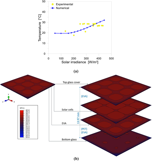
Following the experimental setup of Section 5.1, the attention in the analysis of results was primarily focused on the temperature peaks and trends in the centre of the unexposed glass cover (bottom surface). A sufficiently good match was obtained from the numerical analysis, compared to the experimental temperature measurements, as it can be seen from Figure 12 (a) and (b). This comparative output suggests that – even under the uncertain calibration of the constituent materials (especially their sensitivity to temperature) – FE simulations can provide useful feedback for the analysis of such a complex kind of problems.
The added value of a full 3D FE model is represented by the local and global investigation of temperature distribution in all the BIPV components. This allows to study – at the component level – the non-uniform distribution and the associated effect in terms of mechanical performance. In this sense, Figure 9 (b) shows a typical contour plot for the examined modular unit, and highlights – as expected – the different temperature spread in the BIPV components, glass covers included.
From a structural/mechanical point of view, it is important to remind that the temperature range under the examined operational conditions is limited to ≈40–50 °C, for the monitored experimental scenario. During summer season, these temperatures are expected to rise up significantly, up to ≈85 °C, which is in line with product specifications (Table 1) but also associated to different effects that should be investigated in detail, including also possible variations in the BIPV layout, section and composition, as well as scale effects. Most importantly, it is shown from the present study that major thermally induced mechanical effects in the glass covers derive from the non-uniform temperature spread under ordinary conditions, and from the possible effects due to the combined action of mechanical loads that act on the top glass cover.
6.2 Stress distribution in the glass covers
The stress analysis in the glass covers was carried out by adapting the thermal model of Figure 7 for a static general step with imported nodal temperatures at each time interval of the analysis. This means that the heat transfer elements were replaced by C3D20 brick elements for the BIPV components. Similarly, the loading and boundary conditions were properly modified from the thermal analysis, in order include in the analysis the effect of point-supports at the corners and the temperature sensitivity of the constituent materials. Considering that a 30-second mechanical load was used only as prevailing design action, further possible viscoelastic and creep phenomena were disregarded in the present investigation. This means that the present modelling strategy should be further elaborated before it could be applied to general thermo-mechanical scenarios, i.e. different exposures, mechanical loading configurations or even installation features.
The distribution and propagation of tensile stress peaks – which are of primary interest for the mechanical assessment of the glass covers integrity – revealed maximum values that are not relevant for fully tempered glass, i.e. much lower than the typical design tensile strength.
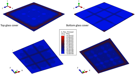
Indeed, the numerical study showed that the estimated stress peaks are affected by the non-uniform temperature spread in the BIPV section. Figure 13 shows in fact a typical example of maximum principal stress distribution for the top and bottom glass covers, at a selected time interval of the thermo-mechanical analysis corresponding to ≈35–40° in the solar cells and in glass. The non-uniform stress distribution emphasizes the local effect of point-supports at the corners, as well as the presence of the embedded solar cells. Most importantly, at the mid-span section of the glass edges in tension, the stress values are still in line with those of Figure 5, based on the simplified effective thickness approach (cold conditions). On the other side, it is possible to see that additional localized stress peaks of Figure 13 are indeed predicted in the order of ≈35 MPa, which are (in average terms) about ≈2–3 times higher than the stress values reported in Figure 5 (cold conditions), and remark a mostly different stress distribution for the glass components, that a mechanical analysis in cold conditions could not capture.
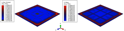
Minor deviations were observed by comparing the maximum principal stress values with Von Mises stresses. Figure 14, in this regard, is derived from Figure 13, by rescaling the legend and blue-to-red spectrum values for the top cover.
Considering the effects of similar phenomena, the use of coupled thermo-mechanical models could guide producers towards a possible optimization of the constituent layers, which includes an in-depth analysis both under ordinary conditions and even more under extreme accidents.
6.3 Bending stiffness and out-of-plane response
A further efficient and practical assessment of the mechanical performance of the BIPV system and its sensitivity to the applied loads can be carried out in terms of out-of-plane bending response analysis.
According to Eqs (7) and (8), the effective bending stiffness Deff of the BIPV Sandwich section can in fact be expected as:
and a major influencing parameter is represented by the shear stiffness of the encapsulant, as well as any possible relaxation of the encapsulant itself due to the progressive temperature increase (i.e. Figure 8).
The bending stiffness Deff can thus suffer for possible unfavourable operational conditions, and hence represent a practical performance indicator for diagnostic purposes. Accordingly, the bending stiffness can be estimated as a function of the effective thickness for deflection hw (Eq. (1)).
An implicit approach to track any possible stiffness modification, in this context, is represented by the analysis of the fundamental vibration frequency of the BIPV floor tile (Bedon and Massi Pavan, 2024). For a linearly supported BIPV module with continuously restrained edges, the theoretical fundamental vibration frequency is in fact given by:
in which a, b are the edge dimensions, n = 1 and m = 1 for the first vibration mode and m* the weight per unit area. Eq. (14) can be thus adapted (with the support of FE models) to account for the specific boundary condition (i.e. point-supports as in the present study), as well as for possible variations in Deff during normal conditions.
In this regard, Figure 15 shows the vibration frequency change for the BIPV under ordinary operating conditions and point-supports at the corners. The thermal scenarios are derived from Figure 12. The fundamental vibration frequency f1,4P is iteratively calculated, for different operating temperatures, from a coupled mechanical modal analysis of the FE model of Figure 12. The numerical results are then compared as a function of the average temperature Tcell,avg that is measured – for each one of those scenarios – in the solar cells. Also, the percentage variation is calculated for f1,4P, as a function of its value at ambient conditions (Tcell,avg = 20 °C).
It can be seen from Figure 15 that even a relatively moderate temperature variation in the BIPV tile components (which can be fully disregarded in terms of mechanical performance of the glass covers) has indeed some mechanical effects on the response of the BIPV tile as a Sandwich section. Accordingly, a frequency reduction of about ≈10% (or more) can be expected under normal operating conditions, and even more pronounced mechanical effects can be expected under higher accidental temperatures (Bedon et al., 2025a, b). Overall, the trend of Figure 15 confirms the role of coupled thermo-mechanical models for possible diagnostic purposes and section optimizations for in-service BIPV tiles. Certainly, the results of Figure 15 are limited to the specific configuration that has been explored in this study, but suggests the potential of the monitoring approach and the role of thermally induced phenomena for the BIPV Sandwich section.
6.4 Comparison of performance indicators and thermal sensitivity
In addition to the BIPV section detailing, the use of bespoke point-supports as in Figure 1 represents an additional influencing parameter, which makes the bending response of the system mostly different from a linearly supported tile (i.e. Figure 4 (b) and Figure 5 (b)) and possibly emphasizes some local phenomena. As such, it requires specifications also in terms of frequency analysis, compared to classical formulations.
For example, the performed numerical study showed that the fundamental vibration frequency of the examined BIPV tiles can be roughly estimated:
with f1,4S given by Eq. (14), and:
Which means that the actual frequency suffers for the effect of point-supports but also for the bonding stiffness of the encapsulant, and particularly is limited by the bound limits at the “layered” (f1,4P,abs) and “monolithic” (f1,4P,full) configurations.
Besides, it can be more efficient to correlate the frequency trends to the shear modulus of the encapsulant (Gint) and the average operating temperature.
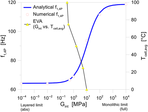
Figure 16, in this regard, shows the vibration frequency change as a function of Gint. It is calculated both analytically, based on Eq. (15), and numerically in ABAQUS (with a glass plate of effective thickness, derived from Eq. (1)). The trend of shear modulus for the EVA encapsulant is also recalled, as a function of the temperature (from Figure 8). It can be seen – as known – that the encapsulant has limited rigidity, and also it decreases with a moderate temperature increase.
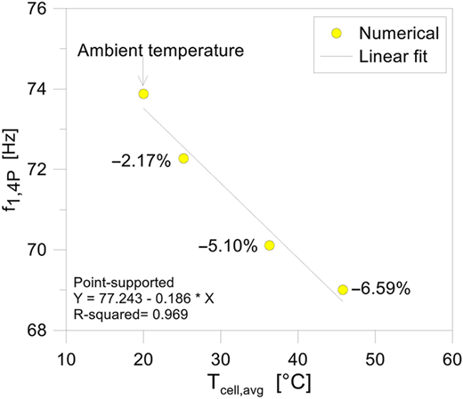
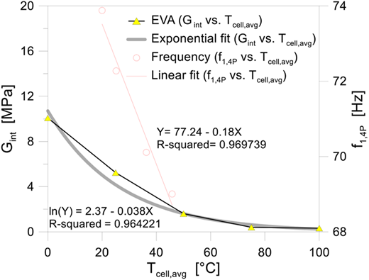
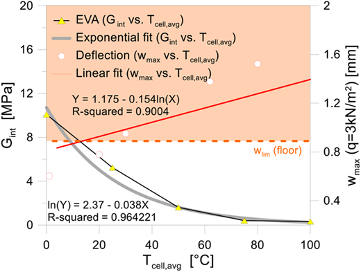
Introducing the refined FE model of Figure 12 (in place of the effective thickness one) for the frequency analysis under different operating conditions, it is possible to correlate the trend of shear stiffness Gint for the encapsulant with the corresponding vibration frequency f1,4P. Figure 17 shows a typical example for the examined configuration and material properties. More in detail, the numerical values of f1,4P are reported as a function of the average temperature in the solar cells, which is rather identical to the average temperature in the EVA encapsulant. Additional comparative results are presented in Figure 18 in terms of numerical deflection.
In Figure 17, it is interesting to note that the f1,4P are comprised between ≈74 Hz (at Tcell,avg = 20 °C) and ≈68 Hz (Tcell,avg = 45 °C), which corresponds (based on Figure 12) to a rather weak shear bonding contribution of the encapsulant. This outcome suggests that the glass covers are mostly “uncoupled” when the BIPV floor tiles are subjected to possible mechanical loads at normal operating conditions. Also, the “layered limit” is expected to occur for relatively low internal temperatures, in the order of ≈80–90 °C.
In terms of vibrational comfort assessment, there are no doubts that similar BIPV tiles are still rather stiff even under normal operating temperatures, and any possible discomfort of pedestrians can be fully disregarded. The measured vibration frequency, in the less unfavourable case, is in fact calculated in the order of ≈63 Hz, which corresponds to a fully rigid pedestrian system for customers (Bedon and Fasan, 2019).
From a mechanical point of view, however, this phenomenon is associated to a progressive reduction of bending stiffness and thus a progressive increase of the corresponding bending deflection, which could also represent a possible critical condition for glass strength and deflection verifications. As such, possible cross-sectional optimization strategies are particularly recommended for unusual boundary conditions and restrains, as well as for severe operating conditions that could further manifest these possible effects. Also, the introduction of specific performance indicators for the comfort prevention of pedestrians could enforce the design and maintenance of similar systems.
7. Conclusions
The mechanical analysis of glass-glass BIPV systems is rather challenging, due to a multitude of phenomena and interconnected effects. Structurally speaking, the thin glass covers are required to protect the embedded electrical components but also to ensure the optimal mechanical functionality and load-bearing capacity. Their design and detailing in terms of thickness and size is thus a priority for many reasons.
According to practical conventional strategies for the design and verification of 2-ply structural glass members, the serviceability deflection and ultimate stress are key performance indicators that can be used to ensure a safe mechanical performance of these systems. Besides, many influencing parameters should be taken into account, due to the intrinsic features and functionality of BIPV tiles. This study, in particular, showed that the non-uniform temperature spread during normal operating conditions still represent a key factor for design and functionality optimization under in-service conditions.
In this paper, the attention was in fact focused on the mechanical performance assessment of point-supported BIPV floor tiles of common use for pedestrian systems. A commercial product, with 0.5 m × 0.5 m its size with 6 mm thick glass covers, was chosen to inspire and preliminary validation a numerical model in ABAQUS.
It was shown that:
Compared to the use of consolidated and efficient, but simplified literature approaches based on the use of effective thickness for laminated glass sections, the coupled thermo-mechanical phenomena in BIPV tiles can induce major variations in the stress distribution for the glass covers.
Additional influencing parameters are represented by the combined effect of mechanical restraints and temperature-dependent material properties: while glass still behaves elastically under moderate temperature changes, this is not the case of the encapsulant materials, which suffer for the temperature increase and reduce the bonding effect for the glass covers of the Sandwich BIPV section. Accordingly, even a minor relaxation can lead to a reduction of the associated bending stiffness, maximizing the effect of possible mechanical loads. For the present study, for example, it was shown that the effect of a 30-second conventional pedestrian load induces tensile stress effects that are apparently negligible for the glass covers. Indeed, the associated deflection progressively increases with the encapsulant relaxation.
An implicitly associated issue is related to vibrations comfort for pedestrians: while the bending stiffness of the BIPV section modifies, the fundamental vibration frequency of the system also decreases. For the examined scenario, a vibration frequency decrease of about ≈7% was observed under ordinary operating conditions, compared to cold conditions. Higher percentage variations can be rationally expected for different section layouts and fixing systems.
To improve the design and safety optimization of BIPV tiles, possible practical recommendations are as follows:
The glass covers should be verified against stress and deflection by taking careful consideration of thermal scenarios and induced effects. An efficient strategy is the use of complex thermo-mechanical models in which the progress of thermal and mechanical loads can be progressively captured.
The design and featuring of the resisting cross-section could take benefit from this refined analysis under ordinary conditions, as the predicted stress and deflection values can significantly differ from estimates in cold conditions.
The use of temperature-sensitive materials – also for the analysis of BIPVs under ordinary conditions – should be preferred.
The design and featuring of mechanical restraints should be carried out by taking care of the interconnected effects (both thermal and mechanical), such as stress concentrations, or deflection increase, etc.
In addition to the stress and deflection analysis for the glass covers, the out-of-plane bending stiffness assessment can represent a powerful performance indicator, particularly for pedestrian systems where possible discomfort could also arise. To improve both the structural safety and comfort level of BIPV tiles, their minimum vibration frequency should be in any case higher than 8 Hz like for pedestrian systems. At the same time, its sensitivity to temperature (and even accidental events) should be properly monitored and tracked to prevent both premature failure and discomfort. A tentative scatter for alert could be set in 5% frequency variation.