The purpose of this paper is to analyze the micro-motion of the cylinder block.
Based on the elasto-hydrodynamic lubrication, a numerical model for the cylinder block/valve plate interface is proposed, with consideration of the elastic deformations, the pressure-viscosity effect and asperity contacts. The influence-function method is applied to calculating the actual deformations of the cylinder block and the valve plate. The asperity contact model simplified from Greenwood assumption is introduced into the numerical model. Furthermore, the relationship between the micro-motion and the operating condition, the sealing belt width is discussed, respectively.
The results show an increase in the discharge pressure causes the tilt state and the vibrating motion getting worse, which can be eased by improving the rotational speed, the sealing belt width and the ratio of external and internal sealing belt width.
The proposed research can provide a theoretical reference for the optimizing design of cylinder block/valve plate pair.
1. Introduction
Swash plate axial piston pumps have been widely used in fluid power systems for their benefits of high power density and efficiency (Yang and Pan, 2015; Canbulut et al., 2009; Shen et al., 2017). As part of displacement chambers are filled with high pressure oil, the cylinder block tends to tip against the valve plate at a tiny zone, and the tipping point varies with the cylinder block rotating. Compared with the rotation, the tipping movement is very weak, so the dynamic variations can be regarded as micro-motion, and it is believed that analysis on the micro-motion of the sliding parts has a significant effect on reducing the time and cost during the design process of axial piston pumps.
Most interest for the cylinder block/valve plate pair lies in the interface performance. The Maha Fluid Power Research Center leaded by Ivantysynova has achieved significant achievements about the interface modeling, Wieczorek and Ivantysynova (2002), Huang and Ivantysynova (2003), Jouini and Ivantysynova (2008), Baker (2009), Zecchi (2013) and Chacon (2014) gradually developed a multi-physics model with consideration of the dynamic term, the elasto-hydrodynamic effect and the thermal effect, which represents the most advanced simulation model. Han et al. (2015) established a partial lubrication model by accounting for the asperities, which implied a better prediction of film thickness and pressure. Wang et al. (2018) revealed the lubricating characteristics for tilt and non-tilt states of the cylinder block, but the dynamic term was not considered.
In addition, some researchers have paid attention to the cylinder block tilt motion. Manring (2000) discussed factors causing the cylinder block tipping failure and proposed an important design criterion, and the non-dimensional tipping criterion equation was further developed by Shin and Kim (2014). Jiang and Yan (2017) explored effects about the rotation speed and the pump structure on the tipping tendency. Yamaguchi (1990) experimentally studied the cylinder block dynamic and found the cylinder block more severe oscillation with the increasing inlet pressure. Kim and Jung (2003), Kim et al. (2005) mounted sensors on the cylinder block and found out the relationship between the film thickness and the operating condition. Bergada et al. (2008, 2012) conducted a series of measurements about the cylinder block dynamic, and another similar work was done by Zhao (2010), but limited to low pressure and speed. Xu et al. (2017) and Zhang et al. (2018) justified that the inertia moment of the piston-slipper assembly at high speed would intensify the cylinder block tilting effect with leakage growing in evidence.
Though plenty of investigations about the cylinder block are admirable, the micro-motion of the cylinder block has been scarce investigated. Therefore, this paper aims at developing a coupled fluid-structure mathematical model for the cylinder block/valve plate interface, furthermore, the effect of the operating condition and the sealing belt width on the micro-motion is analyzed.
2. Mathematical model building
2.1 Micro-motion of cylinder block
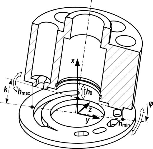
The cylinder block is primarily loaded by oscillating pressure forces resulting from the chamber pressure, which is a function of time and angular position, and the other oscillating force in the axial direction is the frictional force between the piston and cylinder block. The resultant oscillating axial force and the derived moment cause the cylinder block lift away or squeeze to the valve plate. Obviously, the micro-motion changes periodically with the rotational angle. Figure 1 shows the micro-motion of the cylinder block, which can be described by the tipping position φ, the tilt slope k and the mean gap h0, these parameters can also express the film height with non-deformation:
where Rv is the radius of the external seal ring. Considering the deformations reach value close to hcv, the nominal film thickness can be given by:
where δ is the combined deformation for the interface, which can be calculated by the influence-function method (Shi and Wang, 1998; Jiang and Yan, 2019).
2.2 Reynolds equation
The particular form of the Reynolds equation in polar coordinates is shown below. The left terms represent the hydrostatic pressure, the terms on the right hand refer to the hydrodynamic effect and the squeeze effect, respectively:
where pf is the fluid pressure, ω is the rotational speed and μ is dynamic viscosity of the film, which can be expressed as:
where μ0 is the viscosity at atmospheric pressure, αp is the pressure coefficient.
Theoretical researches indicate that, the oil film thickness reaches values close to the combined surface roughness in some small regions, therefore, it is necessary to take the asperity contact into consideration. Some assumptions are developed for this model: Firstly, there are no interactions between asperities, which share the same radius of curvature at the peak, while the whole distribution of the asperity heights is rather close to the standard Gaussian distribution, and the bulk deformation has no influence on the asperity deformation (Greenwood and Tripp, 1971; Greenwood and Williamson, 1966). Secondly, asperities are evenly distributed (Jiang and Yan, 2019). Thirdly, the mating surface of the cylinder block is covered with rigid half spherical asperities, and that of the valve plate is regarded as an elastic half space (Popov, 2009).
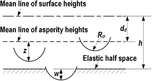
The contacting geometry of cylinder block/valve plate is shown in Figure 2 (Chang et al., 1987). z is the asperity height, w is the vertical deformation, Rσ is the radius of curvature (Shi et al., 1996), dd is the difference of the mean line of the surface and the mean line of the asperities (Sojoudi and Khonsari, 2010).
The asperity deformation can be defined as:
where:
where σ0 is the composite root-mean-square (RMS) surface roughness, which can be calculated as:
where σc and σv are the RMS roughness values of the cylinder block and the valve plate, respectively. Theoretically, the contact of the cylinder block/valve plate interface is plastic, the asperity contact pressure pe and the contact area ae can be calculated as (Abbott and Fristone, 1933; Johnson, 1985):
where H is the hardness of the softer material. The areal density of asperities in contact is:
where ρσ is the areal density of asperities (Li, 2002). Thus, the contact area coefficient is:
In this study, assuming the addition of the asperity pressure does not appreciably change the distribution of the film pressure, so the total separating pressure is:
2.3 Force balance
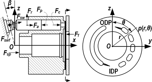
The micro-motion of cylinder block is determined by the external forces as shown in Figure 3. The flow ports on the valve plate are divided into two types, discharge port and intake port, which are separated by the outer dead point (ODP) and the inner dead point (IDP).
The resultant pressing force and tilting moment in y- and z-axis acting on the interface can be expressed as:
where n is the piston index, β is the swash plate angle, A0 is the area of the kidney port of the cylinder block, pn is the displacement chamber pressure, Fsp is the spring force, Rf is the piston pitch radius, f is the frictional coefficient and Fsw is the swash plate reaction force, which can be calculated:
where Fp is the pressure force acting on the piston, Fr is the centrifugal force of the piston-slipper assembly, Fcr is the pressing force between the cylinder and the piston:
The bearing capacity of the interface can be calculated as:
The cylinder block is in dynamic equilibrium, which follows:
3. Numerical calculation
Assuming the first piston starting from the ODP, and the periodic angle for a pump with 9 pistons is 40°, which is defined as one loop. The fluid-structure interaction problem associated with the elasto-hydrodynamic lubrication (EHL) is approached through a partial iteration in coupled solving the fluid and structure domains.
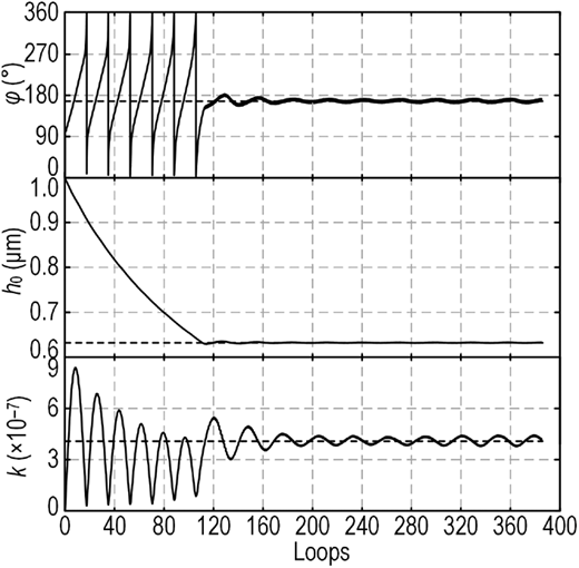
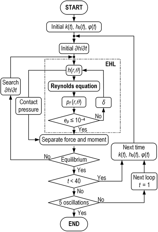
To obtain more precise micro-motion, a stricter criterion of the iterative calculation is presented as (17). It is found that the simulation results present damped oscillations, sometimes the decay is slow, as shown in Figure 4. It can be noticed that the procedure starts to fluctuate around a constant value after about 120 loops; therefore, it is proper to select the loop which is closest to the mean line within the oscillating waves as the final calculating result after at least five oscillations. Figure 5 is the workflow of the simulation:
4. Analysis and discussion
4.1 Effect of operating condition
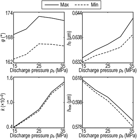
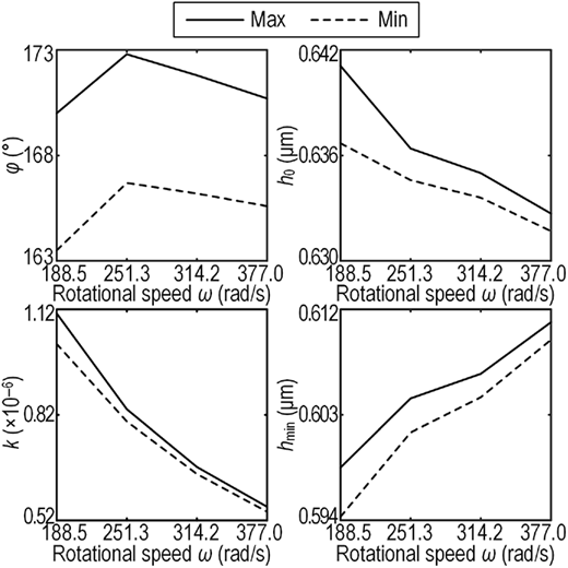
The main factor influencing the micro-motion is the operating condition, which contains the discharge pressure and the rotational speed, Figures 6 and 7 is the simulation result corresponding to the discharge pressure and the rotational speed, respectively.
The tipping position φ presents similar variation with pressure and speed increased, and the maximum value is within the IDP. In fact, a greater value of φ means the opening position of the tilt slope is closer to the discharge region, and that will increase the danger of the film decompression and cause the cylinder block unstable running.
Figure 6 shows that the mean gap h0 and the tilt slope k display inverse variation to the minimum gap hmin, which is a supplementary parameter for the analysis. At a constant speed, an increase in pressure leads to h0 and k increased, hmin decreased, which demonstrates a higher pressure aggravates the tilt state. This plot also indicates that the vibrating motion is get more violent when the pressure is higher, since the variation scopes are increased. However, the tilt state and the vibrating motion could be eased by improving speed, which can be illustrated by Figure 7.
4.2 Effect of sealing belt width
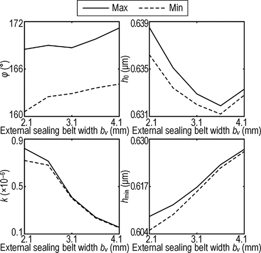
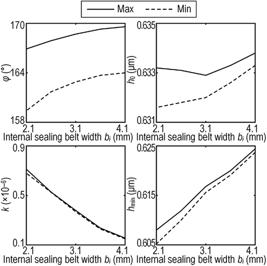
A proper sealing belt width is one of the optimal design of axial piston pumps, Figures 8 and 9 show the relationship between the micro-motion and the external/internal sealing belt width, respectively. Generally, the effect of increasing the external/internal sealing belt width is similar: plots of the tilt slope k identify that the tilt state is eased with the increase of sealing belt width, while the tipping position φ is approaching the IDP, which increases the possibility of film decompression. Furthermore, the vibrating motion is weakening as the sealing belt width increased.
For the cylinder block force balance, the external and internal sealing belt width is a shift between the relationship, as a consequence, λ, the ratio of external and internal sealing belt width is analyzed in this part, which is shown in Figure 10. It can be seen that all the parameters are decreased, indicating that the running stability is getting higher and the tilt state is eased when the ratio λ is getting larger. Additionally, the thinner minimum gap hmin implies more serve abrasion on the external sealing belt. In total, λ should be improved as far as possible in the design:
5. Conclusions
In this paper, the detailed concepts of the cylinder block micro-motion was proposed, and an integrated numerical model was built to observe the influence of the operating condition and the sealing belt width on the micro-motion of the cylinder block.
The cylinder block has a regular micro-motion, which is a function of time and the angular position, reflecting the cylinder block dynamic variations. The simulation results indicate a higher discharge pressure can aggravate the tilt state and the vibrating motion, which can be eased by improving the rotational speed, the sealing belt width and the ratio of external and internal sealing belt width. However, improving the sealing belt width can cause that the tipping position approaches the inner dead point, which might lead to the film decompression, while improving the ratio can result in a thinner minimum gap, which might lead to more abrasion.
Supported by National Natural Science Foundation of China (No. 51775131) and The Tribology Science Fund of State Key Laboratory of Tribology (No. SKLTKF17B12).