The Thames Tideway Tunnel project represents a significant advancement in London’s urban wastewater management, aimed at improving the health of the River Thames by way of intercepting combined sewer overflows (CSOs). This deep tunnel system manages 34 CSOs and directs combined sewage to Beckton Sewage Treatment Works through the existing Lee Tunnel. The operational strategy focuses on effectively managing liquids, solids and gases by minimising CSO discharges to river while protecting vital infrastructure. The system employs a comprehensive supervisory control and data acquisition framework for real-time monitoring and control, which is integrated with advanced hydraulic and air management systems to mitigate odour issues and meet regulatory CSO discharge standards. The testing and commissioning processes, both pre- and post-installation, involved rigorous testing and careful integration with the Lee Tunnel, ensuring seamless functionality. Furthermore, innovative inspection protocols are being developed to maintain the system's integrity, using both traditional and emerging cutting-edge technologies such as robotics and drones for efficient and safe asset assessments. Ultimately, the Thames Tideway Tunnel stands as a cornerstone of London’s urban wastewater management, putting safety, sustainability, operational excellence and environmental stewardship at the forefront.
1. Introduction
The Thames Tideway Tunnel project is a deep tunnel system controlling 34 combined sewer overflows (CSOs) by transferring combined sewage by way of the Lee Tunnel to Beckton Sewage Treatment Works (STW). This project was the third and last in a series of projects undertaken to improve the water quality of the tidal River Thames and some of its tributaries, as part of the London Tideway Improvement Programme (see Figure 1 in Grant and Bailey (2025) in this issue). The first was the upgrade by Thames Water to its five tidal Thames STW – Mogden, Beckton, Crossness, Riverside and Long Reach – to remove the chronic dissolved oxygen sags in the rivers linked to STW effluent discharge. The second was the Lee Tunnel project, delivered by Thames Water, which comprised a 7 km long storage and transfer tunnel from Abbey Mills Pumping Station (PS) to Beckton STW for the interception of the Abbey Mills PS CSO, the largest CSO in the system.
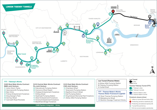
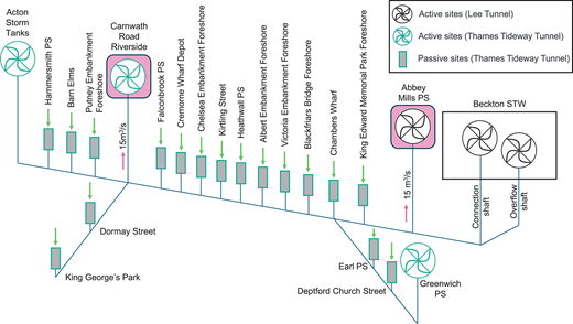
To control its 34 CSOs, the Thames Tideway Tunnel project comprises 24 sites (Figure 1), with the following purposes:
tunnel boring machine drive sites (six)
tunnel boring machine reception-only site (one)
CSO flow interception and tunnel boring machine reception sites (two)
CSO flow interception and short connection tunnel construction sites (eight)
CSO flow interception sites with shafts directly connected to tunnels (two)
CSO flow interception sites that also divert a portion of flows from combined sewers into the tunnel system (three)
sites to modify the sewer network locally (two).
The combination of sewer network management and the partial diversion of flows from combined sewers resulted in not all 34 CSOs needing to be intercepted or locally modified.
The Thames Tideway Tunnel project was delivered by Bazalgette Tunnel Limited (known as Tideway) with some local sewer modifications and the Beckton Storm Tunnel delivered by Thames Water (see Fricker et al. (2025) in this issue).
The CSO interception and tunnel system of the Thames Tideway Tunnel project connects to the Lee Tunnel at Abbey Mills PS and, together, these two systems are known as the London Tideway Tunnels (LTT) (Figure 1). The combination of connecting a new large tunnel system into the Lee Tunnel, an operational deep tunnel system, and works being delivered by two clients presented interesting circumstances unique to this project, such as the following.
The Thames Tideway Tunnel system could not be tested as a system until it was connected to the Lee Tunnel and the Lee Tunnel needed to be taken out of service to make the connection.
There was a significant difference between the operation of the Lee Tunnel and the LTT, with the former having a gravity overflow to the Tideway CSO (located at Beckton STW) and the latter having a pumped overflow to the Tideway CSO by way of the Beckton Storm Tunnel recently constructed by Thames Water.
Asset ownership split. On completion of construction, Tideway will own, operate and maintain the deep vortex drop tubes, concrete shafts and tunnels, while Thames Water will own, operate and maintain the near-surface interception structures (see Grant and Bailey (2025) in this issue).
At the time of writing (October 2025), all sites have been activated, dry system tests undertaken with faults and observations rectified, and two storm tests were successfully completed in July 2025. The teams await a significantly larger storm to conduct the third full-tunnel storm test.
2. Operating strategy
The Thames Tideway Tunnel system operates intermittently, as it is a storm water system, and its operation requires the management of three forms of matter that enter it
liquids – in this case combined sewage (raw sewage combined with rainfall runoff) associated with CSOs
solids – materials and sediment conveyed by way of combined sewage through the tunnel system
gases – primarily air vented in and out of the tunnel system.
2.1 CSO management
The operating strategy for LTTs’ combined sewage flows had three performance objectives – minimise CSO discharges to the River Thames, protect infrastructure assets and be easy to operate.
To minimise CSO discharges to river, LTT limits the following.
The annual CSO volume and frequency of discharges to the river for a typical year from the most polluting CSOs.
The average discharge frequency of the Abbey Mills PS CSO more significantly than those discharging to the tidal Thames, because it discharges to Channelsea River, which is a sensitive tidal tributary of the River Lea.
The CSO discharges in the western reaches of the tidal Thames more than those in the lower reaches, because the upper reaches are used extensively for recreational purposes, such as rowing near Putney.
CSO schemes involving deep storage/transfer tunnels have significant risks associated with adverse transient conditions during filling of both the hydraulic (combined sewage) and pneumatic (air) systems. Transient conditions are the temporary changes in flow that occur when systems transition from one steady state to another. To protect the tunnels and shafts from these risks (Hon et al., 2017), the operating strategy incorporates the following safety measures.
Inflows into the tunnel system at the large CSO sites are proactively limited and stopped during larger storms to prevent potentially damaging transient conditions such as pressure surges and double filling bores that can lead to air-pocket trapping.
To prevent overfilling, inflows into the tunnel system will stop when the combined sewage level in the tunnels reaches set levels before the tunnel system is full. All inflows have to be pumped out of the LTT system, because it has no gravity overflow to the Tideway CSO (unlike the former Lee Tunnel system). Furthermore, the pump capacity is limited. Therefore, inflow must be stopped at some point to maintain a freeboard and protect against flooding at the interception and shaft sites.
The operating strategy had to be easy to understand and needed to avoid complex forecasts, multiple modes of operation or complicated decision making processes.
The operating strategy is set out in the LTT Operating Techniques (OTs), which identify the rules to control the capture and conveyance of the combined sewage in a manner consistent with the performance objectives of the system.
The LTT OTs are a set of operating rules based on fill levels within the tunnel system. They prioritise protecting the most sensitive water bodies, primarily the River Lea followed by the western reaches of the tidal Thames, while incorporating inflow and level controls to protect the LTT assets. When a site’s tunnel isolation penstocks are closed, the flows intercepted at that site are diverted to the river. The LTT OTs include the following.
Two modes of operation – ‘wet weather’ (default) and ‘extreme wet weather’.
Inflow control limits at selected large flow sites. One tunnel isolation penstock closes pre-emptively at these sites and then all penstocks close when inflow control limits are reached to protect the tunnel system and minimise transient condition risks during high flows.
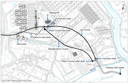
As the level in the tunnel system rises, the following sequence occurs. Tunnel isolation penstocks at lower priority sites are closed first when the LTT are 85% full. Then, the Tideway PS pumps flow through the Beckton Storm Tunnel (Figure 2) to the Tideway CSO for discharge to the river when the LTT are 92% full during wet weather or 81% full during extreme wet weather to make more storage space available for flows from the western CSOs and Abbey Mills PS CSO during larger rainfall events. Then, the tunnel isolation penstocks at the western CSOs close when the LTT are 96% full. This is followed, lastly, by the tunnel isolation penstocks closing at the highest priority CSO interception at Abbey Mills PS when the LTT are 98% full.
Under the extreme wet weather mode, the tunnel isolation penstocks at all sites that discharge into the River Thames are closed at a lower level when the LTT are 57% full to reserve tunnel volume for storing combined sewage from Abbey Mills PS that would otherwise go into the River Lea during an extreme storm. Inflow control limits at a selected site are initiated at the start of extreme wet weather mode.
The default mode of operation is the wet weather mode. The operating system is manually switched to extreme wet weather mode when the 24-hour weather forecast is for more than 22 mm of rain. The 22 mm depth of rainfall is equivalent to a greater than three-year return period 2-hour catchment-wide storm.
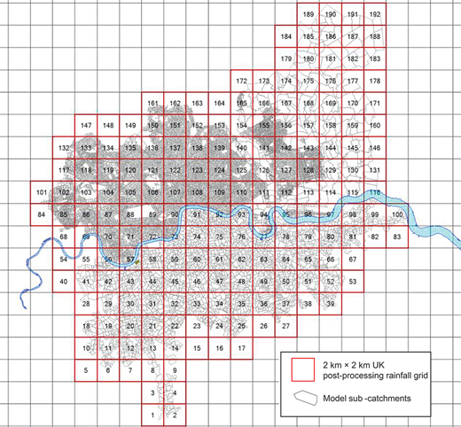
Tideway and Thames Water receive weather forecasts from the UK Met Office four times a day, which are 24-hour forecasts of catchment-wide weighted average rainfall, with rainfall weighted on an impermeable/impervious area within a 2 km × 2 km Met Office forecast grid across the catchment (Figure 3). The Tideway LTT supervisory control and data acquisition (SCADA) system is set to alert the operator when the forecast rainfall is greater than 22 mm. Additional control measures are incorporated into the default mode of wet weather operation that safeguard the system by pre-emptively closing one tunnel isolation penstock and initiating inflow control at selected sites when the tunnel fills to 35% full if an extreme storm event materialises due to an incorrect weather forecast.
Through this operating strategy, the tunnel system is controlled in a manner that results in less than five CSO discharge events to the River Thames in a typical year, and only one discharge into the River Lea on average once every 10 years.
For most storm events, the system captures and treats flows that would have been discharged to the river, in particular flows with the most concentrated sewage (known as the ‘first flush’) following a storm. For larger storms, once the conditions that led to the tunnel isolation penstocks being closed have abated, the penstocks will reopen, enabling flows to enter the tunnel system again and stop being discharged to the river. The opening sequence uses level setpoints in the reverse order of the closing sequence so that discharges to the river stop in the order of receiving water sensitivity, which means Abbey Mills PS discharges stop first.
2.2 Materials and sediment
The materials and sediment conveyed by the combined sewage from the sewer network and into the tunnel system are managed primarily by the design of the tunnel inverts and the floors of chambers having gradients that are self-cleansing (Plant et al., 2023).
2.3 Air management
The project’s Development Consent Order (HMG, 2014) requires the system be operated in accordance with the Air Management Plan (Thames Water, 2013), which is reflected in the LTT air management system.
The LTT air management system integrates the active ventilation plants and air treatment units installed by Thames Water for the Lee Tunnel with the ventilation plants and air treatment units installed by Tideway for Thames Tideway Tunnel into a comprehensive system designed to minimise the formation of hydrogen sulphide and meet regulatory requirements. The Thames Tideway Tunnel has three active ventilation plants (at Acton Storm Tanks, Carnwath Road Riverside and Greenwich PS) and 17 passive ventilation plants. Air treatment units are provided at all sites (Figure 1). Active sites are provided with ventilation fans and passive sites are not. Active ventilation plants were provided at Abbey Mills PS and Beckton STW during construction of the Lee Tunnel.
Minimising air entrainment that could lead to large air pockets becoming trapped in the system during tunnel filling is principally managed by de-aeration structures incorporated into the CSO interception works (see Fricker et al. (2025) in this issue). Air entrainment is further minimised by the operating control modes.
The air management system operates under specific control modes as follows.
Tunnel empty. Air is extracted and treated at Carnwath Road Riverside and Abbey Mills PS to ensure that there is an average of one full air change per day. This helps minimise the formation of hydrogen sulphide. Air inflow from strategically placed inlet dampers and through the air treatment units at passive sites balances the air extracted from the active ventilation sites.
Tunnel filling. With head space (active site’s shaft not yet air-locked), air is extracted and treated at each of the active sites (Acton Storm Tanks, Carnwath Road Riverside, Greenwich PS, Abbey Mills PS and Beckton STW) at the maximum rates for each site. Together with the de-aeration system at each site, this helps to minimise air entrainment/air pockets that could cause pneumatic effects such as geysers at the shafts. Without head space (tunnel level risen such that an active site’s shaft is air-locked), active air sites operate at their minimum rate to prevent over-extraction of air from the filling shafts.
Tunnel static. Active air sites operate at their minimum rate to prevent over-extraction of air.
Tunnel emptying. Active air sites operate at their minimum rate as the dropping level draws in additional air from the passive sites.
Air released from the active and passive sites is treated through activated carbon media in the air treatment units.
3. System control
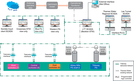
The LTT system is controlled by a SCADA system. This system enables automatic system operation as well as providing an operator interface to manually control the flow of combined sewage and air.
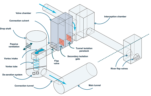
Three main works contractors (MWCs) designed and built the tunnels and the CSO interception infrastructure. Their works included the provision of control panels at each site, enabling local control if necessary. Figure 4 shows typical standard hydraulic components of a CSO interception, with the sizes of each component varying in line with the hydraulic design flow at the respective site. CSO capture into the tunnel system is automated by the site’s tunnel isolation penstocks, which are normally open but will close based on the operating strategy set out in the LTT OTs.
The system integrator contractor (SIC) provided telemetry units at each site and an overarching SCADA system, known as the Tideway LTT SCADA (Figure 5), enabling automated control and remote control. The SIC also ensured that the Tideway LTT SCADA system was integrated with Thames Water’s Regional and Lee Tunnel SCADA systems. Five remote client workstations were provided (Figure 5) – two from where the system could be controlled (only one in control at a time) and three from where the system could be only viewed.
3.1 CSO control
The rules of the LTT OTs to control the opening/closing of the tunnel isolation penstocks rely on the flow rates entering the system and the level of combined sewage in the tunnel system. The system design incorporates monitors and sensors into the works to provide the necessary data and the SCADA system incorporates control flags that react when flow/level setpoints are reached in order to automate penstock control in accordance with the operating rules.
Level monitors in the shallow sub-surface interception works at each site are used to derive flow rates into the tunnel and are therefore an essential element of inflow control. Level monitors in the shafts are used to derive combined sewage levels in the tunnel system. Proximity switches are used to determine whether penstocks are open or closed. Hydraulic or electrical actuators are used to open/close the penstocks. Battery uninterruptible power supplies are provided, which ensure that – in the event of power or communications failures – the tunnel isolation penstocks are closed.
Data from the level monitors located upstream of the new river flap valves are sent to Thames Water. Thames Water uses this level data to determine when a CSO is discharging to the river – information that Thames Water provides to the Environment Agency as part of their reporting obligations.
3.2 Air control
The LTT system includes a complementary air management system to reduce the risk of odour releases and meet the regulatory requirements for odour and hydrogen sulphide (Georgaki et al., 2017).
As described in Section 2.3 the air management system has four modes of operation. Figure 6 shows the pattern that applies during the ‘tunnel empty’ mode, when the air is changed once per day. The control flags in the SCADA system that automate fan speeds all use tunnel level data.
The air treatment units have hydrogen sulphide, temperature and pressure monitors upstream and downstream of the carbon media. The SCADA system raises alarms when pairs of monitors detect a set difference. The hydrogen sulphide monitoring data are used to determine the efficiency of the air treatment units. The differential pressure monitoring data provide information on activated carbon media performance and future media replacement requirements.
4. System commissioning
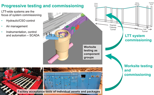
System commissioning comprised testing of the whole LTT system. Before system commissioning could begin, an extensive series of tests were carried out for the works at each site. These included off-site factory acceptance tests of plant and equipment and then worksite testing of component groups of plant by the MWCs, followed by integrated site acceptance testing with the SIC’s systems (Figure 7). Once all Tideway’s sites were considered ready to be put into operation, the next step was to physically join the Thames Tideway Tunnel infrastructure to the Lee Tunnel.
4.1 Integration with the Lee Tunnel
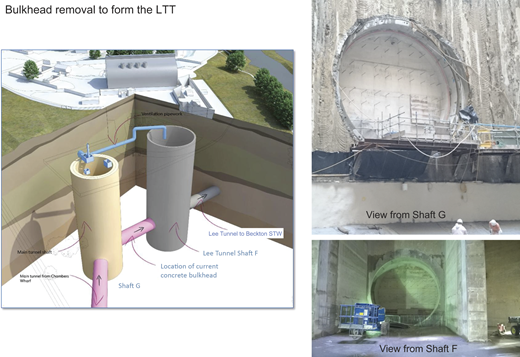
Thames Water needed to take the Lee Tunnel out of service to enable Tideway to remove the barrier separating the two tunnels 66 m underground (Figure 8). The works had to be completed within 14 days during a period when less than 5 mm rainfall was forecast to minimise the risk of discharges to Channelsea River. Thames Water also had to modify parts of the Lee Tunnel so that the two tunnels could be incorporated into one system.
With only three small discharges to Channelsea River during maintenance outages since 2016, the Lee Tunnel has intercepted the Abbey Mills PS CSO with an average of 5 million m3 of combined sewage captured every year. Since the Lee Tunnel was commissioned, the water quality in Channelsea River and the River Lea has steadily improved, with 14 fish species found in a 2023 survey. The risk was that – without the Lee Tunnel in service – any rain over 5 mm could cause a discharge, harming the environment within the Channelsea and Lea Rivers. To manage this, Thames Water
studied weather forecast patterns to choose the best time to start
shortened the work period to finish safely within 14 days
agreed on a mitigation plan with the Environment Agency, including using hydrogen peroxide dosing if needed
led an incident management team to ensure the work was started at the correct moment, done safely and on time.
On removing the barrier, the Lee Tunnel operation – which had a gravity overflow to the Tideway CSO – ceased, and Thames Water started to operate the LTT, which has no gravity overflow. Instead, discharge to the Tideway CSO is now pumped by way of the Tideway PS and the recently constructed Beckton Storm Tunnel. Removal of the barrier also connected the Beckton STW and Crossness STW catchments.
Each STW is fed by a network of sewers, known as a sewerage system or catchment. Usually, each catchment is independent and not connected to others, which means they can be managed and operated independently. Once the LTT became operational, the two sewerage catchments north and south of the River Thames became connected, allowing Thames Water to manage excess flows during storms dynamically. Previously, these catchments were operated independently, sending dry weather flow sewage to Beckton STW in the north and Crossness STW in the south. Now, when it rains, the two catchments operate as one system, with combined sewage from the Crossness catchment entering the LTT system and controlled from Beckton STW in terms of pump-out by way of the Tideway PS. Two large existing PSs – one in each catchment (Abbey Mills PS in the north and Greenwich PS in the south) – can now divert large flows into the Lee Tunnel and the Greenwich connection tunnel, respectively, to be treated at Beckton STW.
4.2 Site activation
The staged process of bringing each Thames Tideway Tunnel interception site into operation was known as site activation. Tunnel isolation penstocks and secondary isolation gates had been closed at all the CSO interception sites before the barrier to the Lee Tunnel was removed at Abbey Mills PS. Once the barrier had been removed, all the Thames Tideway Tunnel’s tunnels and shafts became operational sewers, which changed the working environment, requiring a more restrictive permit-to-work process.
Each sewer connection to the tunnel system (from the CSO interceptions and combined sewer partial diversions) was carried out sequentially. The Tideway System Commissioning Manager, the relevant MWC, the SIC, the relevant NEC3 Project Manager (NEC, 2013), Thames Water and Tideway were all involved in the process of agreeing the go ahead for each connection (activation). This milestone was the point at which CSO flows would be captured into the LTT and the point at which the CSO discharge permit became operational. The sites were ‘activated’ between August 2024 and February 2025.
The activations involved temporary flume removal, the installation of final connecting pieces to join the new works to the existing sewer network and the opening of the tunnel isolation penstocks and secondary isolation gates. As part of the activations, the local site control systems were fully tested (end to end) and integrated into the Tideway LTT SCADA system.
Once activated, combined sewage that would have been discharged to the river was intercepted and flowed into the tunnel system for transfer to Beckton STW for treatment.
4.3 Dry system testing and storm testing
4.3.1 Dry system testing
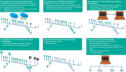
Once all of the sites had been activated and the necessary documentation accepted, a series of integrated dry system tests was undertaken to validate that the system was ready for flow interception, ready to manage odours, the controls worked as expected, plant operated satisfactorily in automatic mode and reporting requirements were understood. Six dry system tests were carried out (Figure 9) in ‘dry weather’ using simulated tunnel level changes, comprising
tunnel isolation penstock opening and closing tests
air management tests to validate correct fan and air treatment facilities operation
inflow control tests
tunnel isolation penstock exercising inhibited when penstocks were needed for tunnel isolations
CSO discharging to the river data transmission tests
control system failure and recovery tests.
4.3.2 Storm testing
Once issues that came to light in the dry system tests had been resolved, the system was ready for storm testing. The purpose of storm testing was to demonstrate that the system operated in compliance with the LTT OTs and validate that the system reacted to filling and emptying events in the correct way. The timing of the storm tests was weather dependent. The tests comprised
storm test 1: half-tunnel levels in extreme wet weather mode (completed)
storm test 2: half-tunnel levels in wet weather mode (completed)
storm test 3: full-tunnel levels in wet weather mode (awaiting large enough storm)
storm test 4: automated operations for a 30-day period (yet to commence).
The aim of the storm tests was to test the entire system performance including tunnel level control, air management, CSO discharge monitoring and odour using both permanent (SCADA) and temporary monitoring equipment. In particular, the following were tested.
Tunnel hydraulics with tunnel isolation penstock response (open/close) to controls as specified by the LTT OTs as tunnel levels and flows rise and fall.
Air management as tunnel fills and empties during storms.
The LTT SCADA, which controls hydraulic and ventilation systems and provides monitoring/alarm data to operations.
Before a sufficiently large storm event occurred to enable storm testing to commence, smaller rainfall events were monitored. Data from permanent air and hydraulic level instruments were validated against temporary installations. A key lesson emerged regarding the level monitoring instruments used for control and compliance reporting. Initially, radar instruments were deployed in deep shafts, while ultrasonic instruments were used in near-surface structures. The level measurement data from instruments installed in the connection culverts were used to calculate flow rates entering the tunnel system, which govern the operation of the tunnel isolation penstocks. With an extended dry period, coinciding with an exceptional year for high-temperature records in London, it became evident that thermal fluctuations were compromising the accuracy of the ultrasonic level sensors. This led to erroneous flow calculations during dry conditions, despite no actual inflows. This phenomenon was termed ‘ghost flows’.
Following a detailed investigation by the MWCs and their instrumentation suppliers, it was determined that the ultrasonic sensors were susceptible to temperature-induced measurement drift. As a corrective measure, all ultrasonic instruments were replaced with radar-based level sensors, including those used to detect discharge events to the river, to ensure reliable and temperature-resilient flow monitoring.
The original system commissioning plan proposed two half-tunnel storm tests. However, due to an extended period of dry weather, a revised approach was adopted. This involved a hybrid test combining storm test 1 and storm test 2 at quarter-tunnel level and then at half-tunnel level. The system operated largely as expected and the control infrastructure performed reliably, with no major faults or disruptions that were considered critical to operations either during or after the test. Mass balance calculations confirmed consistent flow data, and hydrogen sulphide treatment was effective across all sites.
In analysing the storm, the test demonstrated several notable system characteristics due to the high inflow volumes, which led to rapid filling, causing the tunnel isolation penstocks to cycle through opening and closing in quick succession, when switching between weather modes and the different testing setpoints of quarter- and half-tunnel modes. Despite this, the tunnel isolation penstocks responded correctly to setpoint triggers.
Importantly, this storm condition highlighted a critical control aspect related to hydraulic and air ventilation performance in light of rapid oscillation waves created during filling and stopping of the Tideway PS. During the peak of the storm, it was observed that the waves generated from rapid filling in the tunnel caused cycling of the ventilation fans in quick succession between tunnel filling and tunnel emptying modes. This more pronounced dynamic behaviour, driven by the intensity of the storm event, revealed some unique characteristics in the air management system that warranted further consideration and additional dampening of how the Tideway LTT SCADA determines tunnel filling and emptying conditions. Faults and observations were logged for resolution in preparation for the third storm test (at full-tunnel setpoints) and fourth storm test (automated operation).
The observations of rapid wave oscillation while the tunnel was only partially full highlighted one of the benefits of the progressive storm testing adopted as part of system commissioning. This allowed further fine tuning of both hydraulic and air management systems as observed in half-tunnel mode to be completed before full-tunnel testing.
5. Operational tools
Originally, an LTT strategic network model was developed and used for over 10 years to model the LTT system and its integration with the wider sewerage network of both Beckton STW and Crossness STW catchments. The software used was Autodesk’s InfoWorks ICM (Autodesk, 2025a). This catchment model was used to demonstrate CSO compliance, optimise the system design and develop the integrated operational control rules of the LTT system. It was also used to provide hydraulic design flows and boundary conditions used in other modelling tools, including Ansys computational fluid dynamics (CFD) digital models (Ansys, 2025) and physical models. The CFD and physical models were used with a feedback loop to improve the catchment model. The model was also used to further validate the future performance of the LTT as significant storm events were experienced during the period of construction.
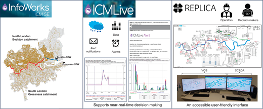
Tideway has recently updated the LTT strategic network model to the latest available network model from Thames Water and created the LTT detailed network model using Autodesk’s ICMLive software (Autodesk, 2025b), which is a live modelling tool that integrates hydraulic models and live data such as weather forecast and tide level data. It provides a forecast look-ahead of network performance and can alert users, either through email alerts or data export, when specified conditions change (e.g. forecast rainfall, flow or level data). Thames Water also uses ICMLive for its catchment models, which were used very effectively in collaboration with the MWCs. Examples at Hammersmith PS and King Edward Memorial Park Foreshore are described elsewhere in this issue (Eccles et al. (2025) and Gonzalez et al. (2025) respectively).
The next step was to transition the LTT detailed network model to make it a more dynamic operational tool to be used for system commissioning. Forecast rainfall data and tide level are now being used with the LTT ICMLive model to simulate forecast rainfall 5 days, 48 h and 24 h ahead and full-tunnel filling 5 days, 48 h and 24 h ahead of time to facilitate go/no-go decision making for storm testing. Email alerts and key datasets are generated and shared with the MWCs, the SIC, Thames Water and Tideway’s system commissioning team to enable planning of activities such as closed-circuit television (CCTV) recording and odour sampling during storm testing. Figure 10 shows an example of an email rainfall alert with hydrographs.
The final piece of creating the operational model of the LTT system, known as the LTT virtual operating system (VOS), brings the dynamic modelling platform into an accessible user-friendly environment for users with Jacob’s Replica software (Jacobs, 2025) (Figure 10). Tideway built the LTT VOS, which provides a hands-on simulation training tool for future users of the Tideway LTT SCADA, in particular the LTT operators. It uses source data of storm events derived from the ICM LTT model and creates an interface similar to SCADA, which the operators are more familiar with.
The benefits of developing the ICMLive model and the LTT VOS can be summarised in three broad categories.
Knowledge management. During system commissioning, it was mainly used to support go/no-go decisions. In the longer term it will be an essential tool for analysis and continuous learning – firstly in optimising the operational protocol, which is weather dependent, and secondly to ensure seamless integration with the existing treatment works and sewer network for effective CSO control.
Training. It provides a virtual environment for new operators to learn and test the tunnel system without the concern that operations could be impacted. It allows operators to safely test drive and practice tunnel operation and decision making during storms, including in infrequent failure mode or contingency operations where a nimble fast reaction is required to ensure safe tunnel operation.
Performance management. It is anticipated that it would be used to demonstrate compliance with the agreed LTT OTs and hence regulatory compliance and overall fit-for-purpose status of the physical asset.
Use of the ICM, ICMLive and the LTT VOS together can lead to better information management and subsequent analysis. This can lead to better decision making that will, in turn, improve operational efficiency and save money in the long term.
6. Inspections
With multiple sites across a wide area (all connected to deep tunnels) entering the LTT system, this is a huge and complex undertaking in operation. With the system being a live sewer and without the temporary infrastructure used for access throughout construction, any human access needs to be meticulously planned to ensure not only the safety of the inspection team but also to minimise any environmental impact from the system being shut down to facilitate access. Even if access was only needed through one or two shafts, the whole system has to be isolated from the sewer network at every site; while the system is isolated, the River Thames and the River Lea are no longer protected from CSO discharges. Furthermore, deep tunnels and shafts carrying combined sewage are hazardous places for people to be. These considerations led to a design philosophy that sought to minimise the frequency and duration for which people needed to enter and work in the system at depth, including
long design lives to minimise maintenance of the structures
self-cleansing velocities in tunnels and benching in shafts to minimise sediment buildup
no mechanical plant located in the base of shafts or inside the tunnels; mechanical and electrical plant is located in near-surface structures, and instruments in shafts are located at high level with access arrangements provided.
Despite these measures, the tunnels and shafts will need to be inspected periodically to verify that the system is behaving as expected and to proactively confirm ongoing structural integrity. The inspections will focus on the general condition of tunnel/shaft linings, tunnel-to-tunnel connection points, tunnel-to-shaft junctions, locations where repairs were carried out in the construction phase and review of the system for sediment levels.
There will be an inspection of part of the LTT system after storm tests as part of system commissioning and another prior to final ‘maintenance handover’ to Thames Water (see Grant and Bailey (2025) in this issue). These inspections will be an opportunity to assess whether the current plan of inspecting tunnels and shafts every 10 years is appropriate.
When the application for development consent was submitted in 2013, it was envisaged that tunnel inspections would be carried out using specialist motorised vehicles and the smaller diameter connection tunnels would be inspected on foot. Since then, developments in robotic and drone technology presented Tideway with an opportunity to explore alternative inspection methodologies to reduce the need for people to enter deep confined spaces. Trials are ongoing, but the expectation is that the inspections prior to final maintenance handover to Thames Water will be done remotely, using a remotely operated vehicle in the tunnels and using drones, cameras and laser scanners (light detection and ranging (LiDAR)) in the shafts. However, as further developments are required before it can be confirmed that remote inspections will be acceptable, person-entry inspections continue to be planned for.
The MWCs have prepared detailed person-entry tunnel inspection plans. Particular challenges with the LTT system include the following.
The need for inspections to be completed in a short timeframe to minimise the risk of CSO discharges that would cause adverse environmental impact.
Scheduling inspections when river temperatures are low enough to minimise the impact of CSO discharges on river ecology if they were to occur.
The requirement for double isolation, with both tunnel isolation penstocks and secondary isolation gates being closed at all sites. The former can be controlled remotely by the SCADA system, but the latter need to be manually deployed.
Over-pumping and management of trapped flows while the system is isolated at all CSO interception sites.
The uncovering, and subsequent reinstatement, of covers buried under hard landscaping to enable access for personnel and equipment to be lowered down shafts, with the use of cranes with secondary standby cranes available.
System ventilation designed, physically verified and implemented to provide a safe working environment within the tunnels.
A communications system able to support effective communication within the tunnels, with minimal installation/removal below ground.
Bespoke emergency response plans and dedicated confined space emergency rescue teams to support the inspection and enact emergency evacuation and rescue of any injured personnel during an entry.
Inspections of the near-surface structures will be undertaken by specialist drones with the use of 4K video (video content with a horizontal resolution of approximately 4000 pixels), image capturing and enhanced LiDAR scanning capability. For structures with limited lines of sight, for example within some high-level connection culverts, personnel entry or use of CCTV is also proposed.
7. Conclusions
Since August 2024, when the first CSO interception was ‘activated’, the Thames Tideway Tunnel project has been improving the health of the River Thames by capturing and diverting millions of cubic metres of combined sewage for treatment before it enters the river. The transition from construction into operation has been hard work, yet extremely rewarding and inspiring. The system is controlled by balancing the need to reduce the volume and frequency of CSO discharges to the river with the need to protect the tunnels and shafts from hydraulic and pneumatic risks, such as geysers, using control rules that are not complex to implement. The commissioning teams from Tideway, Thames Water, the three MWCs (Bam Nuttall, Morgan Sindall and Balfour Beatty (west section), Ferrovial Construction and Laing O’Rouke (central section) and Costain, Vinci Construction Grands Projets and Bachy Soletanche (east section)) and the SIC (Amey) worked tirelessly and collaboratively at each stage of the commissioning process, which involved thorough testing and careful integration with the Lee Tunnel to ensure that everything ran smoothly.
An exciting workstream involved preparing for the deep shafts and tunnel inspections as new inspection methods are being introduced, blending traditional approaches with cutting-edge technology such as robotics and drones for safer and more efficient inspections.
Overall, the Thames Tideway Tunnel, as a key component of the LTT, has been a best practice example of delivering a significant upgrade to a major urban sewerage system, emphasising clear advances in safety, sustainability, operational efficiency and environmental protection.
Acknowledgements
The authors would like to acknowledge Thames Water’s Wastewater Modelling Team (Geoffrey Brown and Richard Seabert) for their input into creating the LTT ICMLive model and Autodesk’s Daniel Moreira and Tideway’s Jamie Glover for helping troubleshoot the LTT ICMLive setup. Special thanks go to Ingrid Lagerberg (Systems Engineering Lead) and Edward Lewis (Project Manager) for their contributions to this paper.