


1300007 Giant new Kattupalli yard and port puts India at forefront of Asian shipping
By Tatamangalam S. Ananthakumar and Karatha Jayesh (February 2014)
Contribution by Sydney Xavier
It would be interesting to learn more about the planning and technical considerations that led to the choice of Kattupalli in Tamil Nadu as the preferred site for India's new shipbuilding yard and port (Ananthakumar and Jayesh, 2014). For example, the ship production output of 465 000 t is very impressive but where will the workload come from? What are the soil, seismic and wind conditions and what reinforcement cover was used in this extreme marine environment? Where are the quarries, and were local road and rail infrastructure upgraded as part of the project?
Authors' reply
With regard to location, the government of Tamil Nadu was keen to promote trade and development of Kattupalli port was a natural consequence. Unfortunately, the authors are not in a position to comment on the commercial prospects.
Soil strata are predominantly silty sand with an intermediate clay layer and dense sand at the bottom. The piles rest on dense sand at a maximum depth of 52 m. Kattupalli falls under zone III as per IS 1893 (part 1):2002 (BIS, 2002) and the port is designed to be earthquake resistant in compliance with the code provisions. For structural design, a basic wind speed of 60 m/s as per IS 875 (part 3) requirements (BIS, 1987) has been adopted. Reinforcement cover is 75 mm for pile foundations and 50 mm for superstructure works. Maximum aggregate size is 20 mm.
Rock was sourced mainly from two quarries located at Chettipuniyam (90 km away) and Srikalahasti (110 km). Road connectivity between the Kattupalli and the adjacent Ennore port is in progress, but rail connectivity was not envisaged in the first phase of Kattupalli.
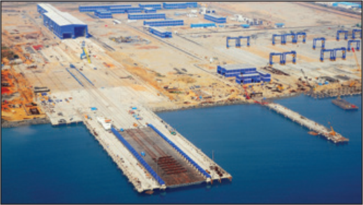
Given the exposed location, how was the port designed against earthquakes, wind and corrosion?
Given the exposed location, how was the port designed against earthquakes, wind and corrosion?
REFERENCES
1200034 Delivery of subway line 9 in Seoul, South Korea – lessons in public–private partnering
By In Keun Lee and Jong-Ho Shin (November 2013)
Contribution by John Parker
Lee and Shin (2013) comment on the death toll per km during construction of Seoul subway lines, noting the significant and welcome improvement from 2·1 deaths/km on line 1 in the 1970s to 0·31 deaths/km on the first phase of line 9.
However, phase 1 of line 9 is 25·5 km long and this rate equates to eight deaths in total. To reduce the total expected number of deaths below 1 on the 14 km second phase of line 9, the death rate would need to improve by a factor of more than 4.
What lessons have been learned from phase 1 that will allow such an improvement to be achieved? Are any other initiatives in place?
Authors' reply
From the start of construction of line 9, a systematic safety approach was introduced including regular site visits by experts, strict safety-checking procedures and enforcement against unsafe practices. Most activities were organised and executed by the client, Seoul metropolitan government.
However, some participants passively followed the safety system rather than actively implementing it. As such, though the safety management system worked well, there were limits to achieving higher standards. Much of the reduction in the death toll on line 9 was also due to developments in technology, improvements in site management and increased social concerns on health and safety generally.
An analysis of the accidents in phase 1 shows that most were fully or partly related to personal carelessness of behalf of the individuals involved. Achieving further reductions in the death toll requires a greater recognition of safety and active involvement in the safety programme of all participants. A social environment also needs to be created on site which discourages all unsafe practices.
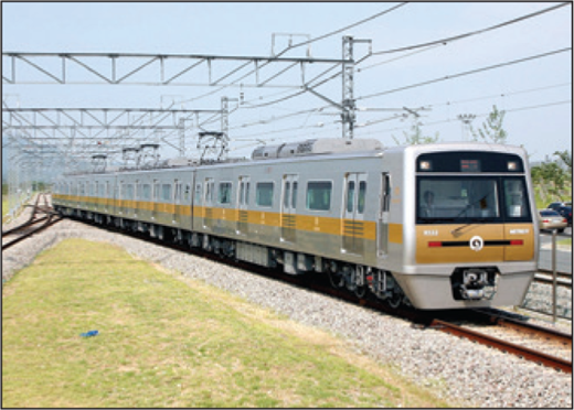
Eight people died constructing the first phase Seoul subway line 9
Eight people died constructing the first phase Seoul subway line 9
REFERENCE
1200038 The importance of understanding computer analyses in civil engineering
By Alistair Borthwick, John Carpenter, Barry Clarke, Roger Falconer and Jon Wicks (August 2013)
Contribution by Richard Dean
Borthwick et al. (2013) provided an excellent if partial antidote to the illusory magic of finite-element software. The geotechnical perspective occupied the least space in the paper but probably involves the most uncertainty and the most need for caution and research.
The authors correctly assert that, ‘routine [ground] investigations do not provide [adequate] data’, and that, ‘UK ground investigations are often not fit for purpose’. The situation is worse in less affluent parts of the world, where investigation, laboratory equipment and training are scarce and/or may be error-prone. There are also huge areas of the globe where there are frozen, collapsible, expansive, liquefiable and/or residual soils, the properties of which differ from the transported soils and reconstituted soils that are often used as the basis for constitutive models.
Furthermore, there is a wide and confusing variety of apparently different constitutive models available in the literature, a relative absence of comprehensive and detailed scientific validation, a relatively small number of mainly simpler models available in commercial software, and an inherent inadequacy of many of these in terms of anisotropy and cyclic-loading capabilities.
There also seems to be a great need for education about scales, broadness of scope and lateral variability. For instance, a minor slope failure affecting a small region of a soil body may be identified by software as ‘the’ important, limiting issue because it occurs before a missed but much more serious and major failure affecting tens or hundreds of metres. Or vice versa. This can lead to a hurried and expensive remediation of the wrong problem.
Another example would be where a single computer analysis is done based on a single set of soil parameters and soil type presences and layer thicknesses, rather than the multiple analyses needed to explore both parameter value uncertainty and system uncertainty.
There is finally the issue of validating computer software products. Do they do what they say they do correctly? Do they correctly refuse/warn about soil parameters that are obviously wrong? Does the help system and documentation adequately identify the appropriate uses and limitations of the software?
How can ICE help resolve these issues?
Authors' reply
The contributor confirms that the use of numerical methods in geotechnical engineering is fraught with problems and that the use of numerical methods has to be treated with caution.
Numerical methods linked with appropriate ground investigation and the correct constitutive model performed by someone competent in those methods are a valuable means of gaining an insight into the uncertain behaviour of the ground using scenario analyses. Unfortunately, as the contributor points out, there are many instances where this is not the case.
It is clear that, if numerical methods are going to be more widely used in geotechnical engineering and with confidence, there is need to select the appropriate constitutive model using representative geotechnical and geological models but including an assessment of hazards, which takes into account local variations.
There is also a need to develop a full understanding of the changes that are imposed on the ground, which creates the need for an appropriate structural model. Indeed, it would be better to move towards an analysis of the soil structure problem. This raises a number of challenges that the contributor has highlighted.
It is clear an adequate ground investigation is required, which has been highlighted on many occasions over the years. Moreover, those using commercially available software should be aware of the assumptions and limitations of the computer codes. It is also clear that those interpreting ground investigation data and using these techniques should be competent to do so. However, this is not always the case. This example illustrates the need for engineers to develop appropriate skills, which is a requirement of professionally qualified engineers.
In addition to individual members taking responsibility for their professional development, ICE is also considering how to resolve the issues raised in the paper in other ways that support the broader engineering community. For example, the ICE structures panel has been investigating the production of a verification and validation manual.
The authors believe that continuing professional development activities and university education will eventually encompass the need for a critical expert attitude towards analysis – it is a matter of time and resources.
Contribution by John Endicott
Figure 5 of Borthwick et al. (2013) shows the 2004 retaining wall collapse at Nicoll Highway in Singapore. The caption states, ‘investigations suggested the most likely cause lay in the design of the retaining wall, which proved insufficient to resist the earth pressure. This was attributed to the use of an inappropriate soil model, which overestimated the soil strength at the site and underestimated the forces on the retaining walls in the excavation.’ This is incorrect. In fact, the committee of inquiry found that the government's experts had come to premature conclusions partly because there was a lack of data made available before the inquiry. Their first reports did blame incorrect use of Plaxis and asserted that forces on the walls were underestimated. However, it later became apparent that the forces measured in the struts at the location of the failure were as low as 2/3 of the design values – the design for the wall allowed for 1·5 times the forces that were being measured.
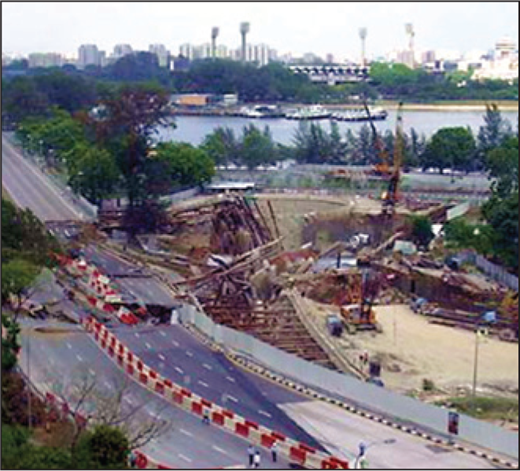
The Singapore highway collapse was not entirely due to incorrect soil modelling
The Singapore highway collapse was not entirely due to incorrect soil modelling
It was apparent that some of the connections of the struts to walers were failing weeks before the collapse and it was later realised that the connections were not able to sustain the design loads at levels 7, 8 and 9. Level 9 was the lowest at the time. The Singapore government later employed an expert in structural steel, who carried out laboratory tests that confirmed the inadequacy of the connections.
The final report of the committee (Magnus et al., 2005) attributes the initiation of failure to failure of the connections at level 9 followed by level 8. Total collapse was due to inadequacy of the system to redistribute the forces that arose due to the loss of the strutting.
All experts in their second meeting considered the state of the diaphragm walls as interpreted from deflections measured by inclinometers at the failure location. They concluded that even when the connection at level 9 was beyond repair there was only one plastic hinge developed in the diaphragm walls. There was rotation about the bottom of the wall but there was no other hinge necessary for a mechanism to develop.
It is true that Plaxis was used by a method that Wong Kai Sin from the National University of Singapore said, 2 months before the collapse, was not correct. However nothing was done about it at the time. In the event, although the wall did not have an appropriate factor of safety, nevertheless when the level 9 connection was failing the wall had a reserve of capacity.
The Singapore government's experts' first reports in effect said that their use of Plaxis demonstrated that the collapse was due to base failure of the soil below excavation level and kick-in of the toes of the walls. They considered no other matter. A quick look at the inclinometer data showed that their use of Plaxis was not right.
Even by noon on the day of the collapse, when the workers had given up trying to repair the level 9 connections, the toes of the diaphragm walls to either side of the area of the collapse had not moved forwards. It was unfortunate that experts, when asked to write reports on the reasons for the collapse, did not look at the relevant data that showed the mechanism of deformations right up to imminent total collapse.
Authors' reply
The authors are very grateful to the contributor for this important correction to our comments about the Nicoll Highway collapse. This emphasises the points raised in the paper and highlighted by the previous contributor.
REFERENCES
1200043 London Olympic Park underpass leads to better understanding of cast iron
By Martin Kirk (August 2013)
Contribution by Mike Mulheron, David Jesson and Paul Smith
Kirk (2013) explores the reserves of strength demonstrated by cast-iron structures and suggests that, where fatigue is not an issue, it is safe to increase the allowable stress limit in tension to 75 MPa.
This is significantly above the limits suggested by BD 21/01 (46 MPa; HA, 2001) and traditional limits on working stresses in cast-iron members (23 MPa).
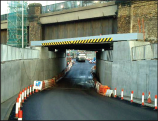
Understanding graphitisation of cast iron can ensure the right analytical approach
Understanding graphitisation of cast iron can ensure the right analytical approach
While there is no doubt that cast iron can demonstrate significant tensile strengths, work on cast-iron water mains suggests that caution is required: variability of tensile performance, the brittle nature of observed failures and degradation processes, such as graphitisation, can all affect structural performance (Belmonte et al., 2007).
Our work has shown that the nature of the graphitisation process is likely to determine the appropriate analytical approach: loss-of-section (ultimate tensile strength and remaining wall thickness) or fracture mechanics (defect size and stress intensity factor) (Jesson et al., 2013).
Could the author explain how the analysis undertaken took into account the potential for deterioration, particularly inside the sewer pipe, and its likely consequences?
Author's reply
I confirm that no specific studies on graphitisation were carried out. It should be noted that the bridge owner carries out maintenance and replacement of elements in line with its maintenance regime.
With the bridge being some 150 years old, various components such as barrels and hangers have been replaced over the last few decades. The study concentrated on the change due to the construction of the new underpass and leaving it in position permanently.

