

Yachihe Bridge in China is the longest steel-truss, cable-stayed bridge in the world and the tenth longest overall. Completed in 2016, its 800 m main span carries the new Guiyang–Qianxi dual carriageway over the Yachihe River gorge. It is also the first cable-stayed bridge to be erected using a cable crane, and its concrete-box-girder side spans feature the first use of cable anchorages in the middle of the outer web. Furthermore, geometry alignment during deck closure was achieved by adjusting cable forces rather than by using counterweights. This paper describes the configuration and numerical analysis of the innovative cable anchorage, discusses the challenges and solutions involved in using a cable crane for construction and details the novel closure techniques adopted for the steel-truss deck.
1 Introduction
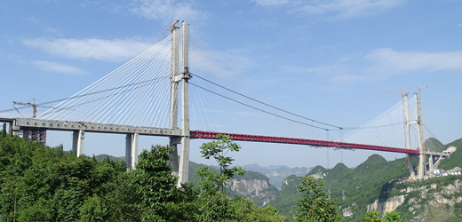
Yachihe Bridge has set a new record as the world’s longest steel-truss cable-stayed bridge (Figure 1). The dual carriageway bridge, which is also the tenth longest cable-stayed crossing, is part of the new 72 km Guiyang–Qianxi highway in Guizhou province, southern China.
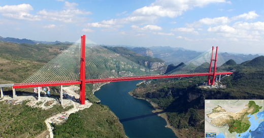
Yachihe Bridge is the tenth largest cable-stayed bridge in the world and a striking landmark on the new Guiyang–Qianxi highway
Yachihe Bridge is the tenth largest cable-stayed bridge in the world and a striking landmark on the new Guiyang–Qianxi highway
The highway has been delivered by Road & Bridge International under a US$1·2 billion engineer, procure, construct, operate and transfer contract. It has cut journey times between Guiyang and Qianxi from 150 minutes to just 50 minutes.
Yachihe Bridge was designed by Second Highway Consultants and built by Road & Bridge South China Engineering for a contract sum of US$116 million. Construction consultancy was carried out by Tongji University. Work on the bridge started in August 2013 and it opened to traffic in July 2016.
The bridge is a hybrid cable-stayed structure (Figure 2). The 800 m main span is a steel-truss deck and the side spans are twin-box concrete girders 27·7 m wide and 8·2 m deep. The pylons are ‘H’ shaped with heights of 243 m and 258 m on the Guiyang and Qianxi sides, respectively.
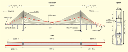
Additional stiffness is provided by side-span piers located 76 m and 148 m from each pylon. The decks are supported by 192 site-assembled multi-strand stay cables. These are arranged in fan configurations and vary from 103 m to 425 m long, with the heaviest weighing 43 t.
The bridge is in remote, mountainous terrain and 305 m above an unnavigable river. Large-scale excavation was also prohibited for environmental reasons. These constraints limited the side spans to 220 m, making the ratio of side span to main span of 0·275 the smallest of the top ten cable-stayed bridges (Table 1).
Top ten cable-stayed bridges built in the world (main spans in bold)
| No. | Name | Year | Span arrangement | Deck type | Main span | ||
|---|---|---|---|---|---|---|---|
| Length: m | Side-to-mainspan ratio | Deck | Erection | ||||
| 1 | Russky Bridge | 2012 | 384+1104+384 | 0·348 | Hybrid | Steel box | Derrick crane |
| 2 | Sutong Bridge | 2008 | 500+1088+500 | 0·460 | Steel box | Steel box | Derrick crane |
| 3 | Stonecutters Bridge | 2009 | 289+1018+289 | 0·284 | Hybrid | Steel box | Derrick crane |
| 4 | Edong Yangtze River Bridge | 2010 | 275+926+275 | 0·297 | Hybrid | Steel box | Derrick crane |
| 5 | Tatara Bridge | 1999 | 270+890+320 | 0·303, 0·360 | Hybrid | Steel box | Derrick crane |
| 6 | Normandy Bridge | 1995 | 357+856+357 | 0·417 | Hybrid | Steel box | Derrick crane |
| 7 | Jiujiang Yangtze River Bridge | 2013 | 232+818+358 | 0·284, 0·438 | Hybrid | Steel box | Derrick crane |
| 8 | Jingyue Yangtze River Bridge | 2010 | 398+816+230 | 0·488, 0·282 | Hybrid | Steel box | Derrick crane |
| 9 | Incheon Bridge | 2009 | 340+800+340 | 0·425 | Hybrid | Steel box | Derrick crane |
| 10 | Yachihe Bridge | 2016 | 220+800+220 | 0·275 | Hybrid | Steel truss | Cable crane |
To balance the weight of the steel truss main span, unusually large and heavy concrete box girders were used for the side spans. This also afforded the opportunity to develop an innovative anchorage for the stay cables, which are anchored in large holes in the middle of the outer webs.
The site constraints also ruled out conventional use of derrick cranes, barges and incremental launching (Isohata and Hanzawa, 1997) for erecting the steel truss deck. After extensive research, a cable crane was adopted – a world first for cable-stayed bridge construction.
This paper describes the configuration and numerical analysis of the innovative cable anchorage, discusses the challenges and solutions involved in using a cable crane for construction and details the novel closure techniques adopted for the steel-truss deck.
2 Innovative cable anchorage solution
The anchoring of stay-cables in a bridge deck is a key element of cable-stayed bridge design. Two main factors need to be considered. Firstly, connections between the cables and deck need to be reliable so that the large cable forces can be safely and efficiently transferred into the deck. Secondly, the cable anchorage zone needs to provide enough space and access for cable installation, stressing, maintenance and replacement.
There are three commonly used cable anchorage types for concrete box girders, as shown in Figure 3. Figures 3(a), 3(b) and 3(c) show stay cables anchored respectively at a cross beam within the girder, under the outer web of the girder and under the bottom flange of the girder. For Yachihe Bridge, the stay cables were anchored in the middle of the unusually deep outer webs.
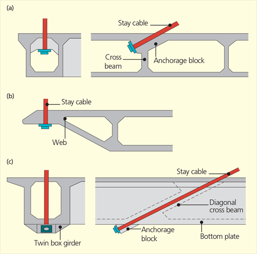
Common stay-cable anchorage types: (a) cable anchored at cross-beam within the girder; (b) cable anchored at web outside the girder; (c) cable anchored at bottom slab of the girder
Common stay-cable anchorage types: (a) cable anchored at cross-beam within the girder; (b) cable anchored at web outside the girder; (c) cable anchored at bottom slab of the girder
The cables are anchored in 2 m dia. circular holes in the 8·2 m deep, 0·7 m wide box-girder outer webs at 8 m centres. The webs are thickened 0·25 m each side for 1·2 m around each hole, and are stiffened laterally with post-tensioned cross-beams. Vertical stiffening is provided by 32 mm post-tensioning bars with a tensile strength of 1030 MPa. These are fixed to the top and bottom of the webs at 0·8 m intervals between holes.
The holes themselves are lined with 60 mm thick curved steel plates connected to cable guide pipes (Figure 4). The plates and pipes are cast into the webs as prefabricated units complete with shear studs and anchor blocks, ensuring smooth and effective load transfer between the deck and the cables.
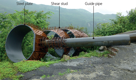
Prefabricated steel anchorage housings were cast into the concrete box side-span girders every 8 m
Prefabricated steel anchorage housings were cast into the concrete box side-span girders every 8 m
A detailed analysis of the innovative cable anchorage solution was carried out to investigate its structural performance. A local three-dimensional finite-element model was established using Ansys 15.0 software (Figure 5). There were 446 325 solid elements in the elastic model, with girders and anchorages simulated by Solid95. Stay cables, longitudinal and vertical prestressed tendons and formwork travellers were also included in the model. Structural information including geometries, cross-sections and material properties were taken from the proposed design drawings.
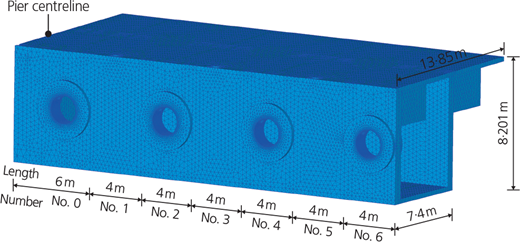
Numerical three-dimensional model for side-span cable anchorage zone analysis
Numerical three-dimensional model for side-span cable anchorage zone analysis
Two load cases were considered in the model. Load case 1 was the maximum cantilever stage during construction, with the first seven segments of the concrete deck activated (0 to 6). The concrete deck was temporarily fixed at the pier centreline during the cantilever construction stages to avoid lateral and longitudinal movements.
Load case 2 was the most unfavourable condition after completion, based on a combination of dead loads, live loads, temperature loads and settlement. The forces and displacements at the boundaries of the cable anchorage zone were taken from the global finite-element model.
Figure 6 shows the principal tensile and compression stress contours under load cases 1 and 2. Numerical results at each end of the concrete deck section under analysis were distorted due to boundary effects in the completed condition, so only the results of segments 1–4 are shown in Figures 6(c) and 6(d).
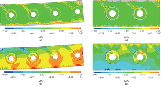
Stress contour of side-span cable anchorages: (a) principal tensile stress during construction; (b) principal compression stress during construction; (c) principal tensile stress after completion; (d) principal compression stress after completion (stress in MPa)
Stress contour of side-span cable anchorages: (a) principal tensile stress during construction; (b) principal compression stress during construction; (c) principal tensile stress after completion; (d) principal compression stress after completion (stress in MPa)
It can be seen from Figure 6 that the concrete deck is mainly under compression with principal tensile stress less than 0·9 MPa and principal compression stress under 10 MPa. The exception is stress concentration zones at the top and bottom of the deck caused by the prestressed tendons and formwork travellers. Figure 6 also shows that tensile and compression stresses along the guide pipes are larger compared with the other stresses in the webs.
The principal tensile stresses are mainly caused by shear, which is due to the vertical components of cable forces and self-weight of the concrete deck. The vertical prestressed tendons were therefore arranged around the holes to resist shear.
The numerical analysis revealed that the cable anchorage solution exhibited good structural performance. It also facilitated construction, avoiding the need for temporary working platforms for cable erecting and stressing.
3 Innovative construction solution
Construction of cable-stayed bridges requires rigorous preparations and careful attention to achieve satisfactory results from quality, productivity and safety perspectives. For Yachihe Bridge, the situation was more critical than usual due to the following factors.
Conventional construction methods, such as a derrick crane picking up and lifting deck segments from below, were not possible as the site was in a steep gorge with limited access by road and river.
Steel trusses are more rigid than steel box girders and the error adjustments are restricted by high-strength bolt connections, thus sophisticated geometry control was crucial to achieve successful closure of the main span.
A tight construction schedule and frequent stoppages due to poor weather required rigorous management of available working time.
A 350 t capacity cable crane was adopted for erection of the main-span steel-truss deck segments (Figure 7). This consisted of load-bearing main cables, hoisting cables, traction cables, saddles, anchorages, trolleys and an electrical system. The saddles were mounted on 3·5 m cantilevered brackets at upper cross-beams of the pylons (Figures 7(c) and 7(d)) and provided support and guidance for the main cables.
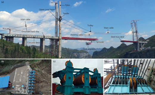
A 350 t capacity cable crane was used to erect the main span: (a) main components of the crane; (b) main cable anchorage; (c) main cable saddle prior to installation; (d) main cable saddle in situ (view from underneath)
A 350 t capacity cable crane was used to erect the main span: (a) main components of the crane; (b) main cable anchorage; (c) main cable saddle prior to installation; (d) main cable saddle in situ (view from underneath)
The main cables consisted of two sets of 12 wire ropes of 60 mm diameter, with a span-to-rise ratio of 13. The deck segments are suspended from four trolleys running on the main cables. Traction cables moved the trolleys horizontally and hoisting cables moved the segments vertically in relation to the trolleys.
Static and dynamic load tests were carried out on the crane before it was put into service to check safety and serviceability and also to understand its structural behaviour and fundamental characteristics (Hu and Shen, 2014).
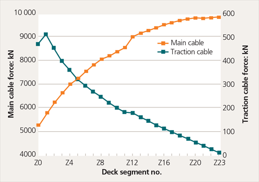
Figure 8 shows main cable forces and traction cable forces during erection of steel truss segments Z0–Z23. The main cable force increased gradually as the deck cantilever length grew longer and the maximum tension was up to 9853 kN. However, the traction cable force decreased from 513 kN to 10 kN as the deck length extended, finally reducing to nearly zero when closure segment Z24 was erected.
Main cable forces and traction cable forces towards the side spans to offset horizontal deformations towards the middle during use of the cable crane.
Main cable forces and traction cable forces towards the side spans to offset horizontal deformations towards the middle during use of the cable crane.
4 Construction challenges
As the bridge and cable crane shared the same pylons, the pylons deformed horizontally towards the centre – up to 100 mm at the pylon tops – during erection of the deck segments. The deck vertical deformations and stay cable tensions were also changed by the cable crane loading, which increased the complexity for bridge alignment and cable force control during construction.
To reduce the cable crane influences on the bridge, four additional groups of temporary anchored back-stays were used between the pylons and the ground beyond the side spans. Each back-stay consisted of 12 steel strands of 15 mm diameter.
By stressing the back-stays with jacks to certain values determined by numerical analysis, the pylons were pre-cambered towards the side spans to offset horizontal deformations towards the middle during use of the cable crane.
The deck segments were joined with high-strength frictiongrip bolts and each joint typically took 3–4 h to complete, during which ambient temperature could change. However, the cable crane was more sensitive to temperature variation than the steel truss. Taking Z10 segment as an example (cantilever length 188 m), the vertical displacement of cantilever tip and cable crane would be 10 mm and 23 mm respectively if the temperature rose by 1°C.
The incompatibility of the cable crane and bridge movements due to temperature change could have resulted in the new segment weight being transferred from the cable crane to the bridge cantilever tip before all the bolts had been tightened. This could have put shear loading into the bolts, for which they are not designed.
To avoid the bolts bearing shear forces, the following measures were adopted.
The new segment erection time was carefully arranged to take place between 2.00 a.m. and 7.00 a.m., during which the ambient temperature was stable.
Sufficient electric wrenches were provided to tighten the highstrength bolts at the top and bottom chords simultaneously, so construction time was shortened.
Shear forces were mainly borne by the webs of top and bottom chords, so high-strength bolts at the webs were tightened first, followed by the top and bottom plates of the chords.
Temporary connections between cantilever tips and the new segment were made using a specified percentage of drift pins and temporary bolts with diameters larger than the high-strength bolts (Figure 9).
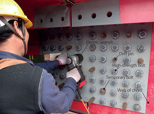
Splice plates and high-strength friction-grip bolts were used to join the steel truss segments together. Temporary drift pins and bolts helped to minimise the risk of putting shear loads into the bolts
Splice plates and high-strength friction-grip bolts were used to join the steel truss segments together. Temporary drift pins and bolts helped to minimise the risk of putting shear loads into the bolts
5 New closure techniques
Cable-stayed bridges are statically indeterminate structures with stay cables suspending decks. As such they are much more flexible than conventional continuous bridges, especially for long-span cable-stayed bridges (Freire et al., 2006).
On Yachihe Bridge, the cantilever length was nearly 400 m before main-span closure. This posed special problems for the bridge closure given the high precision requirements for the steel-truss deck bolted connections, the large deformations in the vertical and lateral directions, and expansion and contraction under temperature variations.
Deck configuration adjustment is a key step prior to closure of a cable-stayed bridge. Substantial counterweights are usually the first choice for getting appropriate vertical alignment of the cantilever tips (Ishikura et al., 2012; Mison et al., 1997; Morgenthal et al., 2010). However, in this case the geometry adjustment was achieved by optimising cable forces.
The bridge stiffness was relatively small for nearly 400 m long cantilevers. If all stay cables (1–24) had been tensioned to their final state, the vertical deformations of the cantilever tips (Figure 10) would have been 1·96 m higher compared to the final alignment, and at an angle of 1·179°.
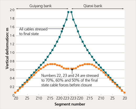
Geometry alignment of the deck before closure – the cantilever tips were brought nearly level by optimising cable forces of the outer segments
Geometry alignment of the deck before closure – the cantilever tips were brought nearly level by optimising cable forces of the outer segments
By optimising tensioning of stay cables during erection (Chen et al., 2000; Janjic et al., 2003), stay cables 1–21 were stressed to their final state and cables 22, 23 and 24 (both in the side and middle spans) were tensioned to 70%, 60% and 50% of their final forces, respectively. This reduced the deck deformations to 0·62 m higher than the final alignment with an angle of only 0·007°, meeting the closure precision for high-strength bolt connection.
Considering deviations would occur between the expected deck alignment and geometry in situ during construction (Kite et al., 2012), a small amount of counterweights were applied to the cantilever tips and their effects on the deck vertical deformations are shown in Table 2.
Deformation of the deck cantilever tips using counterweights
| Counterweight: t | 2·8 | 5 | 8 | 10 | 12 | 15 | 20 |
| Deformation: mm | −9 | −16 | −25·6 | −31·9 | −38·3 | −47·9 | −63·9 |
The bridge closure was scheduled for May 2016. Local temperature statistics from 2005 to 2015 were collected (Figure 11) and analysed for predicting the temperature during closure construction as the weather was very changeable at the site.
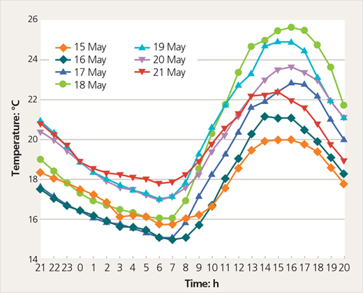
Average daily temperatures from 2005 to 2015 were analysed to help predict the closure temperature
Average daily temperatures from 2005 to 2015 were analysed to help predict the closure temperature
In total, 48 h of field observations of cantilever tip geometries and temperatures were carried out immediately before closure to determine the length and construction temperature of the closure segment. The premise of field observation was that the observation conditions should be as close as possible to conditions during closure, including bridge boundaries, weights and locations of temporary loads.
Concrete blocks of an equivalent weight to the closure segment were suspended by the cable crane at the centreline of the main span (Figure 12). Subsequently, the distances, elevations, axes of two cantilever tips, environmental temperature and top and bottom chord temperatures were measured every 2 h.
Concrete weights equivalent to the closure segment were hung from the cable crane at mid-span in the 48 h monitoring period before closure
Concrete weights equivalent to the closure segment were hung from the cable crane at mid-span in the 48 h monitoring period before closure
Figure 13 shows the field-measured results for a 24 h period. It can be seen that the variable amplitudes of distance, axis and elevation of cantilever tips were around 237 mm, 180 mm and 100 mm, respectively in a day. Geometric alignment of the two cantilever tips was largely affected by the temperature and solar radiation, and the temperatures of the environment and the bridge were stable from 0.00 a.m. to 7.00 a.m. with 2°C variation, which was best for the closing construction.
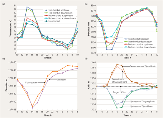
Field observation results during closure: (a) environmental and chord temperatures; (b) horizontal distance between cantilever tips; (c) elevation of cantilever tips; (d) axis of cantilever tips
Field observation results during closure: (a) environmental and chord temperatures; (b) horizontal distance between cantilever tips; (c) elevation of cantilever tips; (d) axis of cantilever tips
The closure segment was prefabricated in a factory and transported to the site in advance. After field observation, the closure segment was cut and drilled in situ to suit the gap between the two as-built cantilevers. The erection of the closure segment was carried out on 18 May 2016 when the temperature was approximately 18°C.
The procedures of closure segment erection were as follows.
Cable crane transported and lifted the closure segment to the gap between the cantilever tips.
Cable crane adjusted the vertical position and angle of the closure segment, followed by installation of splice plates and tightening high-strength bolts on the Qianxi side.
Waited for ambient temperature to rise to the predicted closure temperature, then jacked the deck from both pylon positions while installing splice plates and high-strength bolts on the Guiyang side.
Simultaneously dismantled the temporary fixings between the pylons and the deck.
Continuously observed dial gauges at both ends of side spans to verify the deck could move freely in the longitudinal direction when temperature changed and that closure construction was successful.
6 Conclusions
Yachihe Bridge was opened to traffic in July 2016 and became the longest steel-truss, cable-stayed bridge in the world. The bridge alignment was smooth and the actual geometry matched well with the defined alignment after completion.
It is now a prominent landmark with spectacular and striking features. The bridge has overcome its harsh environment through a number of innovative and unique solutions both in its design and construction.
The bridge success shows that its innovative design, construction and closure techniques have been proved. In summary, the following conclusions can be drawn.
The innovative cable anchorage solution adopted for the concrete box girders has good structural performance, with vertical prestressed tendons arranged around the anchorage zone. This kind of cable anchorage is suitable for concrete girders with large dimensions and is convenient for stay-cable erection.
Yachihe Bridge demonstrates that a cable crane can be successfully used for deck erection of a cable-stayed bridge. The bridge pylons also can be used as supports for the cable crane, helping to reduce the project cost. Temporary grounded back-stays and well-organised construction sequences can overcome the challenges caused by the bridge and cable crane sharing the same pylons.
A cable crane can span large valleys and rivers, so is particularly suitable for bridge construction in mountainous terrain. In addition, cable cranes can have a large lifting capacity and provide precise horizontal and vertical positioning, enabling large prefabricated deck segments to be erected, saving construction time and improving build quality.
For bridge closure construction, geometry alignment and adjustment can be made by cable force optimisation during erection rather than with large counterweights. Field observations are necessary and important to determine the length and construction temperature of the closure segment.

