
Completed in 2021, the new Pooley Bridge in Cumbria is the UK’s first stainless-steel road bridge. It replaced an iconic 1764 stone bridge that was destroyed in a storm. The enforced 18 km detour meant a replacement was quickly needed, but the World Heritage location demanded a high-quality design too. The solution was an elegant and innovative stainless-steel structure that has become a tourist attraction in its own right. This paper describes the design, offsite manufacture and construction of the multi-award-winning crossing.
1 Introduction
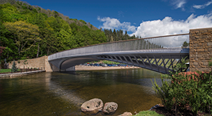
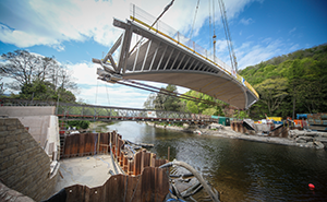
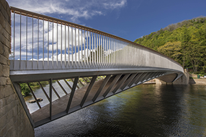
Pooley Bridge in Cumbria is the UK’s first stainless-steel road bridge. It is a 40 m single-span open-spandrel arch bridge, carrying a single road lane and two footpaths over the River Eamont with a composite stainless-steel-and-concrete structure (Figure 1). Its width varies between 7.5 m and 9.5 m.
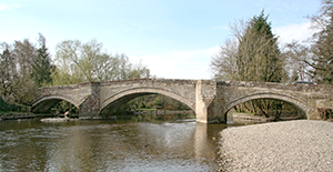
The bridge is located at the outflow of Ullswater in the Lake District National Park, in a site of special scientific interest (SSSI) both for ecology and geomorphology. The destruction of the old bridge by storm Desmond in December 2015 separated the local village – to which the bridge gives its name – from its tourist trade, and local farmers from their pastures, with an 18 km detour. Described as the ‘jewel in the crown’ of Cumbria’s infrastructure recovery programme (Alderson, 2018), the new bridge replaced a listed three-span stone-arched 1764 packhorse bridge, one of 784 bridges damaged and destroyed in Cumbria during the storm and associated flooding (APM, 2021; Figure 2). The bridge’s destruction is described by Matthews and Hardman (2017) and its reconstruction by Tennant (2022).
The requirement for the project was to replace the bridge quickly with a structure that respected the location in the Unesco World Heritage site of the Lake District and that reduced flood risk complying with Environment Agency (EA) requirements.
The challenges to the project were numerous. They included: managing the many stakeholders involved in the project; obtaining unanimity of approval for the design and construction process; building on a site constrained by a mountainside; working in residents’ and café gardens; coping with poor riverside ground conditions; and avoiding causing any future flooding.
The environmental challenges included: working in a site of special scientific interest; EA constraints for working on a salmon river with restrictions due to fish breeding in the gravel shoals; vibration limits from driving sheet piles; gusting winds; and rapid changes in river levels.
Another challenge was the requirement in this tourist village to keep it accessible and minimise the period of vehicle access closure due to the 18 km diversion to reach the other side when vehicle access was prevented. There were also the logistical difficulties of getting large structures and plant to site down Lake District lanes, plus construction during the Covid-19 pandemic. Added to all this was the novelty of the structural form, developing the architect’s concept design into a buildable structure and the lack of design codes for a stainless-steel composite structure.
2 Concept design, structural form and material choice
Three months after the destruction of the 1764 bridge, Cumbria County Council had quickly installed a temporary Bailey road bridge restoring connectivity. Bridge specialist Knight Architects, in collaboration with Mott MacDonald, was then appointed by the council in mid-2017, after a tender process, for the concept design of a new bridge following stakeholder engagement. The objective was to conceive a flood-resilient and future-proof bridge, complying with the current technical standards and the EA regulations, that was supported by the community.
The engagement process involved listening to the community and focusing on its common aspirations to conceive a unanimously supported design that met its need for a high-quality crossing to replace the bridge that gave its name to the village. Various options were shown to the villagers and the process of consultation and the development of the concept design is described in an Institution of Civil Engineers webinar (ICE, 2021).
The chosen bridge design pays homage to its predecessor and other references of British bridge heritage, notably Telford’s Craigellachie cast-iron arch River Spey bridge, and looks to the future, becoming a fitting addition to the site thanks to its lightness and transparency, sitting in the landscape but not dominating the view.
In addition to being a crossing, the bridge was conceived by Knight Architects as a high-quality public space over the river. The footpaths, which are wider at the centre, provide a place for people to stop, talk and admire the landscape. The clear span design does not impede river flow and is resilient to potential future floods as water will be able to flow safely through the structure.
The bridge has a unique structural layout, to avoid horizontal reactions, and a novel composite cross-section configuration (Figure 3). The composite structure is a transparent open-spandrel tied arch with 7.5 m long hidden back-spans that transfer the horizontal component of the arch compression to the deck. This makes it possible to deliver an arch avoiding horizontal reactions given the variable ground conditions, which became apparent after ground investigation.
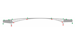
It is an exceptionally slender open-spandrel arch, with a rise of only 3 m over a span of 40 m. The bridge geometry is complex with curvature in both planes. The single clear span minimises environmental impact by eliminating in-river working and mitigates flood risk by reducing obstruction to the river flow during flood events.
The deck of the bridge is of composite construction; the lower arch is of reinforced concrete and tapers from 9 m wide at mid-span to just 1.5 m wide at its bearings. Thrust from the arch is transferred through back-spans concealed within the reinforced concrete gravity abutments and into the top deck by way of bespoke rear link bearings held with 2 m long pre-tensioned anchorages.
The bridge was pre-cambered to take into account dead load and superimposed dead load based on practical experience of other schemes. The pre-camber was limited to 2/3 of the calculated deflection
Lean duplex stainless steel 1.4162 (2101) was selected for the ‘exoskeleton’ of the bridge structure based on both its high strength and excellent durability (Backhouse and Badoo, 2020). The yield strength of duplex 1.4162 (2101) is slightly higher than duplex-grade steel 1.4462 (2205) and 30% higher than carbon steel (S355). The corrosion resistance of lean duplex is equivalent to that of austenitic stainless steels, such as 1.4404 (316L).
Given the site constraints and aesthetic requirements, a weight-sensitive solution was essential. This was supported by the client’s whole-life-cost assessment which demonstrated that lean duplex steel provided a cost-effective solution when considering maintenance savings, removing the need for sandblasting and painting above the river over the 120 year design life (Table 1).
Mechanical properties
| Material | Yield strength: MPa | Tensile strength: MPa | Initial modulus of elasticity: MPa | Density: kg/m3 | Strength-to-weight ratio: kNm/kg | Thermal expansion: ×10−6/°Ca |
|---|---|---|---|---|---|---|
| Carbon steel (S355) | 355 | 490 | 210 000 | 7850 | 62.4 | 11 |
| Austenitic stainless steel (1.4404/316l) | 220 | 520 | 200 000 | 8000 | 65.0 | 16 |
| Duplex stainless steel (1.4462/2205) | 460 | 640 | 200 000 | 7800 | 82.1 | 13 |
| Lean duplex stainless steel (1.4162/2101) | 480 | 680 | 200 000 | 7800 | 85.7 | 13 |
For T ≤ 100°C
The term ‘lean’ relates to the lower alloying content of 1.4162 compared with duplex-grade materials. This lower alloying content reduces the material cost. Lean duplex and duplex steels have a lower coefficient of thermal expansion, which is 20% lower than austenitic steel, which makes composite construction with concrete viable due to reduced interface shear (Table 2).
Overview of duplex alloys and corrosion resistance
| Grade to EN 100088 (BSI, 2014) | Composition: % | Corrosion resistance (PRE)a | |||
|---|---|---|---|---|---|
| Chromium (Cr) | Nickel (Ni) | Molybdenum (Mo) | Nitrogen (N) | ||
| 1.4162 (2101) | 21 | 1.5 | 0.3 | 0.22 | 26 |
| 1.4462 (2205) | 22 | 5.7 | 3.1 | 0.17 | 35 |
| 1.4404 (316L) | 18 | 10 | 2 | — | 24 |
PRE = pitting resistance equivalent = Cr + 3.3Mo + 16N
3 Detailed design
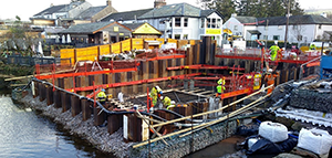
The abutments are conventional reinforced concrete ground-bearing structures constructed within sheet-piled cofferdams. These conceal the back-spans and provide access for bearing inspection and maintenance by way of watertight flood doors. The western abutment is founded on medium-dense sands and gravels, whereas the eastern abutment is founded on stiff glacial clay.
Settlement calculations were undertaken using Rocscience Settle3D software that predicted a differential settlement of 8 mm across the front bearings and a maximum total settlement of 33 mm under dead load. A sensitivity analysis was carried out to establish the critical magnitude of differential settlement that would overstress the structural elements, and this was found to be in the order of 50 mm. A settlement monitoring regime was put in place and trigger levels agreed with the technical approval authority (Table 3).
Settlement monitoring results; predicted values are in parentheses
| Locationa | Front bearing settlement: mm | Rear bearing settlement: mm |
|---|---|---|
| East abutment | 0 (10) | 0 (10) |
| West abutment | 0 (2) | 4.5 (2) |
Accuracy of reflective monitoring points ± 1 mm
The actual settlement at the east abutment was much smaller than predicted, which the geotechnical feedback report attributed to the lack of recovery of consolidation settlement from the original masonry bridge structure loading.
The upper deck is simply supported on the top chord of the bridge with a clear span of 9.2 m. Load is transferred from the upper deck into the lower arch at the crown and by way of the spandrels. The lower chords are in compression and the shear studs perform two functions: lateral restraint to the steel members and load transfer into the concrete arch.
The depth of the upper deck was limited to 250 mm, which gave a slenderness (span/effective depth) of 46, rendering a conventional in situ concrete slab impractical. The structural solution adopted was a composite slab with a 15 mm thick stainless-steel deck plate with stiffening ribs at 0.8 m centres. The deck plate supported the weight of the wet concrete in the temporary condition, and it was pre-cambered by 20 mm. In the absence of any codified design guidance for stainless-steel composite structures, the provisions of EN 1994 (BSI, 2004) were adopted.
Vehicle restraint was provided using a trief kerb detail that provides a passive system containing and redirecting vehicles into the carriageway without additional road restraint. This represented a departure from the UK technical standards for vehicle bridges but was substantiated by testing by the Transport Research Laboratory (TRL), to comply with a normal containment level of N1 as per EN 1317 (BSI, 2010).
Hydrodynamic loading was considered in the design and loss of one spandrel considered as an accidental load case, although the risk of tree impact was considered low from the catchment land use assessment. This approach enabled the adoption of a lightweight stainless balustrade system in keeping with the visual aesthetics of the concept design. The lower reinforced concrete arch was 300 mm thick and varied in width from 9.2 m at mid-span to 1.5 m at the bearing positions. The arch provides lateral restraint to the slender lower chord sections with shear studs between the chord and arch to transfer of longitudinal and vertical shear forces.
The concrete grade for both the upper deck and lower arch was C50/60 in accordance with EN 206 (BSI, 2013) and the detailed design incorporated links for resistance of both compression and shear force. The lower arch was cast before lifting the bridge in place and the bridge could not be lifted until the design strength was achieved. Concrete temperature maturity sensors were cast into the arch to enable real-time monitoring of the in situ strength gain using a smartphone app. The monitoring demonstrated that the 28 day cube strength was achieved after just 12 days, and when the bridge was lifted was more than 80 N/mm2.
Lateral fixity was achieved using a fixed bearing at the upstream west abutment and a single-degree-of-freedom-of-movement bearing at the upstream east abutment. The downstream bearings were fully released to allow for lateral thermal expansion of the structure.
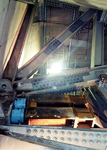
The front bearings were polytetrafluoroethylene-coated spherical bearings that were selected in preference to conventional pot bearings to avoid the need for inspection and maintenance following immersion during flood events. The rear link bearings were designed to resist the uplift loads of 3000 kN and weighed 2.8 t. They were the largest bearings of their type manufactured by Ekspan (Figure 4).
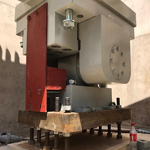
The rear link bearings were designed to resist 3000 kN uplift and weighed 2.8 t each
The rear link bearings were designed to resist 3000 kN uplift and weighed 2.8 t each
Provision for future bearing maintenance was considered from the outset. The rear bearing shelf incorporates an additional pair of holding-down points to facilitate the installation of a temporary tie to allow unloading and removal of the link bearings and a horizontal jacking frame allows safe removal of the front bearings.
The back-spans were concealed within the abutments and installed after the main bridge lift and were connected to the main span using resisting-bolted splice joints. The slip-resistant splice connections utilised approximately 760 pre-loaded M30 grade 10.9 tension-control bolts.
4 Construction
The council was keen to use its existing capital works framework. Eric Wright Civil Engineering Limited (EWCE) was selected after a competition heavily weighted on quality with reference to collaborative working and community engagement. Tendered in January and February 2018, EWCE was appointed under a two-stage contract, including development of concept design and provision of estimates at staged intervals. Stage 1 design was let under an NEC3 Engineering and Construction Contract (ECC) Option C (target contract with activity schedule) and then stage 2 for construction was let under an NEC3 ECC Option A (priced contract with activity schedule).
Knight Architects was retained by the council as concept guardian and the design was developed by EWCE with its consulting engineer GHD and submitted for planning approval to the Lake District National Park Planning Authority in February 2019. Site works started in June 2019. In May 2020, the 320 t deck was placed in one lift. The bridge opening was in October 2020, with full completion in January 2021.
The nature of the NEC contracts created collaboration, allocated risks to parties best placed to manage them and emphasised operating on an open, honest and transparent manner (Leigh, 2020). The use of online project management tools Conject then Cemar aided the process that promoted best practice in management of the contract and encouraged project issues to be understood and managed early. Jointly developing the target cost was helped by Mott Macdonald being co-located in EWCE’s offices and the use of an open-book approach.
Of the £7 million cost, 20% was attributed to temporary works. These included: linkage bridge and associated temporary abutments, ramps and privacy screens and subsequent removal; crane platforms including rock armour wall and subsequent removal; sheet-piled cofferdams; temporary propping of the structure; and temporary tie bars and frames with associated jacks.
EA in-river working permits and the necessity to maintain access to Pooley for as long as possible, limiting damage to tourism, determined the programme. In-river works could not take place from mid-October to mid-June, and peak tourism times, May to October, were to be avoided, requiring careful design and scheduling of activities to meet these constraints. This informed the design and construction programme and allowed EWCE to build in float and key dates for the reception of critical information.
EWCE were responsible for obtaining free access to land to enable construction and so were engaged in negotiation with landowners from appointment. The works necessitated working in two gardens, Granny Dowbekin’s café and the Dunmallard car park owned by Dalemain Estates. Landscaping improvements to gardens, riverbanks strengthening and car park improvements were all agreed, the works free of charge.
Traffic management was important in this busy tourist location. Changing arrangements with the removal of the temporary bridge, crane access and reinstatement of the new bridge required frequent engagement with Highways England and the Cumbrian Highways Management Team. Signage on the M6 and A66 kept motorists informed on the routes to Pooley and Ullswater. Negotiations with Stagecoach were required as there was the temporary truncation of its bus service route through the village; the transportation of school children was re-routed and new bus stops were created.
The team used innovative solutions such as casting converge sensors into the concrete to monitor strength gain, a critical constraint before lift. A movement joint was developed collaboratively; it had not been approved by Highways England. The team liaised with the supply chain, providing analysis to prove its use here.
One of the two car parks in this tourist-dependent village, Dunmallard car park west, was required as the riverside bridge assembly area so site construction began with a replacement car park where the main compound was then located. Diversions with bus companies were agreed.
There were monthly temporary works meetings with EWCE in the role of temporary works coordinator and GHD as designer. Technical notes were produced by GHD with hold positions allowing EWCE to progress with construction, giving actions and limits where advice was sought. Specialist subcontractors were involved in all these meetings, notably WEC Group the stainless-steel fabricator and erector, Ekspan for the bearings, Bill Boley for the temporary ties, Betts for reinforced concrete, EFCO shuttering for the arch propping and the crane operator Sarens.
Work could not commence in-river until 18 June, when flood risk subsided. Rock armour was placed but abutment construction waited until the tourist season ended. The rock armour acted as temporary works to retain the raised and widened Dunmallard car park and protect abutments. The sheet piles were cut down to the top of the base and left in place and a corrosion assessment was undertaken.
EWCE removed the existing Bailey bridge and designed and constructed a temporary road bridge plus a 45 m span pedestrian and services bridge. To minimise disruption for the community and tourists, the work was planned to be completed during a limited window immediately after the August bank holiday.
Design team meetings led by EWCE progressed fortnightly and were attended by GHD, council representatives including its project manager Mott MacDonald, WEC Group fabrication experts and the technical approval authority for Cumbria. The iconic and unusual nature of the structure meant it was subject to an independent category 3 check that was procured by way of Inertia Consulting.
Specific design details were discussed including complex elements with internal stiffeners, site welding, high-quality finishing to the elements, avoiding warping due to heat build-up in welds and many others. WEC Group provided invaluable advice that helped to steer the design to something that was more easily fabricated and streamlined production. Continuing the collaborative and inclusive nature of the project, many of these meetings were held at WEC Group’s nearby Darwen, Lancashire headquarters.
Investigations revealed that the ground was much worse than anticipated, particularly on the eastern bank where the rock-head was deeper than expected below variable glacial till, making piling problematic. This led to a re-evaluation and modification of the design and construction methodology; EWCE, Inertia the technical approval authority (TAA) and GHD rapidly assembled a risk matrix to identify the best options to progress that did not affect the critical path.
The abutments’ construction proceeded with excavation to 6 m behind cofferdams (Figure 5), essentially creating concrete boxes on pad foundations to house the back-spans and a complex arrangement of bearings to facilitate the bridge’s articulation.
5 Offsite manufacture
The tiny site and the requirement to minimise in-river working, together with programme and cost, demanded an offsite construction solution. EWCE approached fabricators in Holland, Germany, France and Yorkshire but finally sourced the structure from WEC Group in Darwen, some 8 km from its offices. On the riverside, the site footprint was very tight, including limited space for delivery, storage, safe lifting and temporary works.
Maximising offsite construction provided many advantages. It minimised interfaces and made managing them easier. It reduced sub-assemblies, assembly risks and construction time in the damp and cold Lake District, making a larger amount of the assembly easier in a factory environment and reducing the range of tools and lifting equipment required. Compatibility and accumulation of component tolerances was easier. In-river working was reduced, with no supporting structures in the riverbed for installation, reducing the risk of pollution and flood risk through possible obstruction of the water flow.
The main span was a fully welded structure comprising trapezoidal stainless-steel chord sections and slender triangular spandrels; this, coupled with the complex geometry with curvature in both planes, made offsite manufacture essential to the success of the project. There were no standard sections available so the whole structure comprised bespoke welded sections of lean duplex plate. Over 2.5 km of welds were laid by WEC Group’s skilled workforce in a factory-controlled environment (Figure 6). Jigs were used to control geometry and there was 100% non-destructive testing of all welds. A trial assembly was undertaken and the bridge was surveyed before transportation to site.
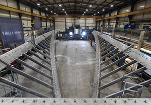
The 110 t steelwork, all made up of bespoke sections, was fabricated in four quarters, taking approximately 22 000 person-hours and strong expertise to complete. The steelwork was subject to a grinding and bead-blasting process to achieve a smooth homogeneous matt finish that faded the welds, preventing organic matter accumulation on the surface and making it possible for the bridge to blend with the natural setting.
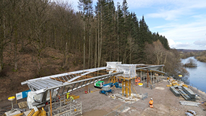
The bridge arrived on site as four 20 m long, 17 t skeletons to be splice-welded at mid-span and at the front bearing beam in the Dunmallard car park by the River Eamont (Figure 7). The logistics of getting the bridge sections along the narrow lanes to Pooley required care. The span was assembled on a jig with temporary supports alongside the river and concrete poured on the assembled structure to form the arch. The jig was created to mount the sections, allowing work to be completed simultaneously throughout different areas of the structure.
The 1920 shear studs were machined from stainless-steel bars and welded to the inner surfaces of arch and deck to create the steel–concrete connection. Subsequently, the concrete part of the arch was cast in the structure on the riverside location and the stainless-steel part of the deck welded before installing the resulting partial structure in place in a single lift. Tie-bars linking the arch springings were used to create a stable system in the temporary situation, and a longitudinal restraint frame within the abutments transferred loads from these bars to the back-spans when installed.
The development of the design by engineers GHD and fabricators WEC Group accommodated the inclusion of well-positioned lifting points that enabled the skeletons to be presented to their counterpart in the correct orientation. The bridge was fabricated with a pre-set that had taken account of the deflection and extension of the bridge that would occur following removal of the temporary supports and application of the loading from the in situ concrete elements.
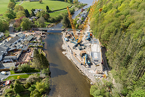
Pooley Bridge’s location at the neck of Ullswater made the bridge lift difficult. In addition to the confined riverbank assembly and lifting area on the west bank, gusts of winds off the fells frequently funnel down the lake and through the narrow valley of the River Eamont. Planning the lift was a painstaking process, not least the logistics of getting one of the UK’s largest mobile cranes to site down twisty Cumbrian lanes. The weight was controlled to achieve a single lift. The weight of the concrete and potential for intense wind required EWCE to use a mobile crane with a capacity of 1350 t.
The lift contractor Sarens provided a Gottwald AK680-3 crane and the bridge had a calculated weight of approximately 320 t including all lifting tackle and rigging. The lift radius was 45 m. To support the rigging process and load the Gottwald’s two ballast trays, one with 650 t of counterweight and the other with 350 t, large Tadano mobiles, an ATF110 and an ATF400 telescopic, were used as slave cranes. The crane took 2 days to rig (Moore, 2021; Figure 8).
A 1.5 m thick geogrid-reinforced platform was required to support the crane loadings with sheet piling to resist edge failure along the riverbank. Detailed surveys of the bridge and abutments were carried out using both laser scanning and conventional surveying techniques to check there were no clashes with the V-shaped openings in the abutments; these checks also had to consider the extension of the bridge during lifting.
Stabilising lift points were cast into the deck. The weight of the bridge was critical and was calculated independently by different methods at 275 t; with the inclusion of the lifting tackle this gave a total lift of 290 t and a crane utilisation of 95%. Load cells were provided at all lift points and a test lift was undertaken on the evening before the lift that confirmed the bridge weight was 286 t and that the settlement under crane loadings was within the calculated limits. On the day of the lift, the lift points were all inspected, and tie bar loads balanced to equalise out differential thermal variations.
On a sunny June day, the lift went as planned and was completed in 3 h (Figure 9). The settlement was 5–10 mm compared with 20–35 mm from ground pre-consolidation from the previous bridge. The load cells on the tie bars and lift points provided essential feedback and design validation (Figure 10). Before the lift, the tie bars were loaded to 650 kN, and this increased to 700–725 kN during the lift. When the bridge was landed, the temporary jacks made final adjustments to line and level and, on release from the crane, the tie-bar loads increased to 1050 kN, which was less than the calculated value of 1200 kN. Retrospective calculations were undertaken to review the tie-bar loads. By increasing the modulus of elasticity of the concrete, considering the actual in situ strength and modular ratio of the densely reinforced concrete arch, good correlation was found with the actual measured tie-bar loads.
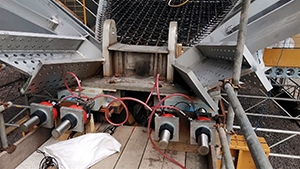
Load cells on the tie bars and lift points provided essential feedback during lifting and installation
Load cells on the tie bars and lift points provided essential feedback during lifting and installation
The back-spans were then connected to the main span using bolted splice connections using grade 10.9 tension-control bolts about 1 month after the main span lift (Figure 11). The tie bars, restraint frame and temporary jacking system held the bridge in place during back-span connection and final level adjustment.
6 Community
Knight Architects had developed its concept design in collaboration with the community and 300 stakeholders including The Prince’s Foundation, Historic England and the EA. The process involved listening to the community and focusing on its common aspirations to conceive a unanimously supported design that met its aspiration for a high-quality crossing to replace the bridge.
Nicknamed the ‘people’s bridge’ in recognition of the involvement of the community through the design and construction, this was recognised in the many awards the bridge has received, notably the Civic Trust’s Special Award for Community Impact and Engagement.
EWCE continued the community engagement process through the detailed design, logistics planning and construction process by organising bi-monthly meetings, door-knocks and newsletters, and promoting news stories on social media and in the local press. The meetings included presentations on design, construction, programme, logistics planning and good news stories on employment of local subcontractors and materials, followed with lively question-and-answer sessions.
It was especially important to communicate around key events such as the delivery of the bridge skeletons and the bridge lifts, with changing car parking arrangements and changes in traffic management. The requirement to get the bridge open as soon as possible was a continued theme of consultation, but the engagement process meant that the community understood the timelines for planning approval and construction.
EWCE’s construction team was embedded in the life of the village, on first-name terms with villagers, making full use of the facilities, lodgings and shopping, within that which was allowed by Covid-19 restrictions. Donations were made to community groups. College and school science, technology, engineering and mathematics visits, apprenticeships and university placements also formed a part of EWCE’s social-value offer to the project. EWCE engaged a largely Cumbrian supply chain.
Villagers commissioned and produced products to celebrate the new bridge: a jigsaw puzzle with the old and new bridge, fridge magnets, a book on the old and new bridge and the local Brack ’n’ Brew brewery produced New Bridge Ale. The villagers have made use of the new public space over the river to congregate and admire the landscape. Facilitated by EWCE, villagers paid for personalised engraved pavers on the bridge which enhance the connection between bridge, people and place and in doing so raised £50 000 for the Pooley Bridge community fund for village projects.
Recognition for EWCE efforts to minimise disruption to villagers was confirmed when project manager, Antony Mulligan, was presented with a salad bowl that had been hand-carved from a tree felled to facilitate the construction of the bridge. It was created by 91-year-old resident, Mr Beer, whose garden was occupied throughout the construction phase.
7 Emissions reduction and sustainability
Sustainable materials use and minimisation of carbon dioxide emissions were important to the project. Calculated using the Institution of Structural Engineers’ tool (Wood, 2022), embodied carbon dioxide used in the construction was 704 t (1.4 t/m²).
Material choice was based on aesthetics (durability in terms of how the bridge will look over time) and whole-life cost. Using lean duplex stainless steel made it possible to deliver a bridge that, while looking contemporary, ages naturally. The 100% recyclable material has durability without maintenance, not requiring sandblasting and repainting over the river. It has 25% more structural capacity than conventional steel. The structural elements of the bridge were cut from stainless-steel plates then welded to lessen material use. WEC Group used its automated system to generate efficient arrangement of plate use (tessellation) and so the plates yielded 85% material utilisation with the remainder returned to supplier Outokumpu for recycling.
The slender design made possible by the high-strength stainless steel reduced the materials used and their associated embodied carbon dioxide content. The duplex steel has a fifth of the embodied carbon dioxide compared with the global average for stainless steel, due to using 85% recycled content and low carbon dioxide energy at Outokumpu production sites. Cumbrian stone was used for abutments.
Emissions were further reduced by the engagement by EWCE of a largely Cumbria-based supply chain. The steel fabrication came from Darwen, which was probably the nearest place that EWCE could source it, after approaching fabricators in Holland France, Germany and Yorkshire.
As a Unesco World Heritage location (Lake District National Park), an SSSI and spanning a salmon river, it was absolutely essential that during construction there were no accidents or environmental incidents that might impact on the area’s outstanding beauty. The River Eamont is designated within the River Eden special area of conservation and the River Eden and Tributaries SSSI. Riverside and village working required management, from limiting when work with vibration was undertaken to using silt-busters to manage run-off. EWCE engaged PBA Ecology, which had been involved in the planning process, to undertake twice-weekly environmental audits. A continual liaison with the EA occurred.
With abutments and crane platforms built into the river, flood modelling for permanent and temporary works was undertaken. Consequently, several properties through the duration of temporary works received additional flood protection, with free-of-charge garden improvements at the same time, to mitigate the risk. Biosecurity was paramount and all gear used for in-river working was thoroughly disinfected before being used on site: ‘Defra [Department for Environment, Food and Rural Affairs] check, clean, dry protocol’ was the mantra.
In obtaining the planning permission, among the supporting environmental information EWCE had to supply: heritage statement for the removal of remnants of the destroyed listed structure, habitats regulations assessment, fisheries assessment (salmon, salmon trout, crayfish, lamprey, otters), geomorphological statement (Pooley Bridge’s citation as an SSSI included its geomorphological profile), ecological impacts statement, bat activity survey and aquatic macrophyte survey, all with accompanying method statements for ecological protection.
8 Safety
Consultation with the community through design and delivery was key to developing safe working methods and ensuring community safety at all times. There was the requirement to maintain a safe, non-motorised, temporary bridge crossing across the river for as long as possible, allowing access to popular walks, homes on the western side and access to Ullswater cruisers.
The requirement to reduce in-river working led to the design being a single span, which was lifted as one piece, with no supporting structures in the riverbed during installation that made the lift as safe as possible.
Construction health and safety was factored in during the design development process. The use of duplex stainless steel brought significant benefits to safety during maintenance that was a key client requirement, as stainless steel requires far less maintenance through its life cycle, avoiding hazardous above-river working such as shot-blasting and painting.
Offsite factory fabrication in a controlled environment ensured high-quality welding and testing was done without the need for working at heights. There was no noise pollution outside the factory. Working offsite reduced the need for travel to site and the associated time away from home and family for those involved.
With the arrival of Covid-19, the council asked the contractor to stop works. EWCE demonstrated that it could work safely in compliance with the Covid-19 guidelines. The company needed to hit in-river work deadlines and delay would result in a year on the programme. The works were deemed ‘essential infrastructure’. The site closed for 2 weeks to establish secure working practices including extra cleaning, extended welfare facilities, programmed break times, new tool-box talks on personal protection and modified working practices to reduce or avoid contacts.
Integration of permanent and temporary works allowed focus on constructability, with maintenance built into the design and not retrofitted, allowing for health and safety to be considered for maintenance. The works were undertaken without any health and safety incidents.
9 Conclusion
Pooley Bridge opened in Cumbrian style with the passage of a local farmer’s 300 sheep, walking his flock between pastures without taking them on an 18 km road journey. The bridge has become a tourist destination in its own right, bringing additional visitors to the village (Figure 12).
It is very rare that a new piece of infrastructure receives such universal acclaim. The replacement Pooley Bridge has achieved this despite being an uncompromisingly modern replacement for a much-loved 1764 listed stone bridge, located in a Unesco World Heritage site and in a dual-listed SSSI.
Despite the excellence of its architectural and engineering design, the novelty and practical use of duplex stainless steel, its embracement of best practice in construction, the community engagement in its design and construction, the difficulties of construction in its precious location and its resilience to climate change, what has really captured the enthusiasm of people who have seen the bridge is its beauty and the way it complements the landscape.
The project has received recognition from the professional institutions and best-practice organisations for overcoming the challenges of all aspects of the project, community engagement, construction, sustainability, innovation, offsite manufacture, architectural and civil engineering design, aesthetics and its regional prominence (Figure 12).
Among the full list of 22 awards, commendations and final shortlisting for Pooley Bridge are: ICE North West Medium Sized Project Award 2021, BCIA National Infrastructure Commission Design Principles Award 2021, Structural Steel Design Awards 2021, CIHT Engineering Award 2021, Civil Engineering Contractors Association (NW) Best Civil Engineering Project of the Year over £5 million 2020, IStructE NW Engineering Award 2021 and Constructing Excellence Awards Civil Engineering Project of the Year 2021.
Acknowledgements
Hector Beade, Knight Architects; Laura Liddington, Knight Architects; Andrew Backhouse, Outokumpu; Antony Mulligan, Eric Wright Civil Engineering; Gavin Hulme, Eric Wright Civil Engineering; Derek Connolly, WEC; Stephen Hall, ex Cumbria CC; Craig Mitchell, Mott MacDonald; Ian Rowley, Mott MacDonald; David S. Brown, Mott MacDonald; Haroon Ashraf, GHD; Andrew Wilson, GHD.
