
With the rapid development of modern science and industrial technology, single metals or alloys are restricted by working conditions and cost. It is challenging to meet the requirements for current applications. Copper (Cu)–steel bimetal composites, composed of copper and steel, have performances of the two metals and low cost. They have drawn extensive attention worldwide and have been developed by many scholars for many years. The new preparations are studies to promote performances of the copper–steel bimetal composites and many literatures have also reported different applications of the copper–steel bimetal composites. Up to today, the developing copper–steel bimetal composites have made a great progress. This paper is mainly concerned with the progress of research on the preparation of copper–steel bimetal composites. The preparations are classified according to the forming state of copper and steel. Furthermore, the industrial applications of copper–steel bimetal composites and the prospects of future development are introduced.
1 Introduction
Copper (Cu) and steel are the most widely used metal materials. With the evolution of metallurgy technology in ancient times, the application of these two metals is more than 2000 years old. However, the importance of these two metals will not be reduced as time flies. Starting from the twenty-first century, copper and steel materials still play an essential role in modern industry and daily life. Materials are increasingly demanded with the development of the contemporary industry. However, the single metal or alloy, which is restricted by cost or properties, has difficulty meeting the requirements in some particular working conditions. As a consequence, great attention has been paid worldwide in recent years to bimetal composites formed by the combination of dissimilar metals at the layer structure.
Bimetal composites, which use a variety of advanced composite material technology, are made from two kinds of metals with different physical, chemical and mechanical properties and become metallurgically bonded at the interface.1–7 Composed of two dissimilar metals, bimetal composites have all of their respective advantages. Therefore, bimetal composites could not only overcome their weaknesses, but also take full advantage of them. Hence, copper–steel bimetal composites have excellent corrosion resistance, tribological and mechanical properties and saving expensive non-ferrous metals. In the future, copper–steel bimetal composites will have broader application prospects to substitute for many traditional materials.
In terms of copper–steel bimetal composites, copper matrix components usually use copper alloys with excellent tribological properties – for example, tin (Sn) bronze, lead (Pb) bronze and aluminum (Al) bronze – or cupronickel and brass with excellent conductive thermal conductivity and corrosion resistance. For steel matrix parts, usually chosen is carbon (C) steel or alloy steel with low cost and excellent mechanical properties. According to requirements, stainless steel is sometimes selected.
2 Preparation of copper–steel bimetal composites
With the rapid development of industries, the preparation technologies of copper–steel bimetal composites have improved much in recent years. According to the preparation state of copper and steel, the preparation methods can be divided into three: solid–solid method, solid–liquid method and liquid–liquid method.
2.1 Solid–solid method
The solid–solid method is the preparation method in which copper and steel are both in the solid state during the preparation process. It mainly includes the powder metallurgy method, plastic forming method and welding method.
2.1.1 Powder metallurgy method
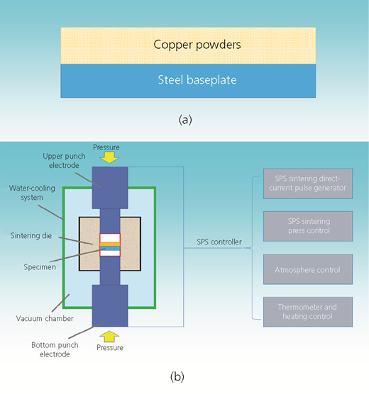
The powder metallurgy method is a standard method for preparing copper–steel bimetal composites. Copper alloys exhibiting excellent tribological properties and corrosion resistance usually serve as a coating layer. According to the application environment, the chemical compositions of the copper alloy are generally changed with steel matrix materials. Sometimes according to the requirements, the bimetal will also use steel alloy powder as a cladding layer. The powder metallurgy method is usually used in manufacturing complicated structure bimetals, which are difficult to machine or have high-cost workpieces. Now this preparation method has been widely applied in fabricating copper–steel bimetal components, such as engine bearings, bushings and molding guide plates.
The preparation procedures of the powder metallurgy method usually make metallic powder lay on the surface of a baseplate, as shown in Figure 1(a), and then the coating powders combine with matrix layers to form metallurgical bonds by diffusion during cold-pressing and sintering.8–10 Due to copper alloys being oxidized easily, sintering atmospheres are generally chosen to be a reducing gas. The sintering temperature is lower than the melting point (Tm) of pure copper. When copper alloys are intended to be used as the coating layer, the steel baseplate is often plated with a copper coating in order to improve the bonding strength of copper and steel. Nevertheless, defects such as edge leakage, burning and uneven bonding forces always occur in this process.
Researchers have developed an anti-rust surface treatment process to simplify the preparation.11 This process can reduce defects and improve the interfacial bonding strength between copper and steel through the surface treatment process without plating with a copper coating. Regarding the aspect of raw powder processing, some scholars have studied the effects of aluminum bronze powders with acid pickling on the sintering properties.12 The results showed that the thicker oxide film was removed by pickling treatment of aluminum bronze powder, and the hydrophilic powders exhibited better sintering characteristics.
In recent years, one of the most advanced preparation methods, the spark plasma sintering (SPS) method, is applied in powder metallurgy.13–21 A schematic diagram of SPS is shown in Figure 1(b). This method is a new and rapid sintering technique where sintering occurs in an instantaneous high-temperature field. The instantaneous high-temperature field is induced by pulse energy, discharge pulse pressure and Joule heat. Compared with the conventional sintering, the SPS method has advantages of low sintering temperature, rapid heating, short sintering time, energy saving, environmental protection, safety and many other features. However, due to its expressive and sophisticated equipment, the SPS method has the disadvantage of high cost. With the improvement of the preparation method and production facilities, mass production by the SPS method is being popularized gradually. In the future, this technology will play an important role in the preparation of copper–steel bimetal composites.
2.1.2 Plastic forming method
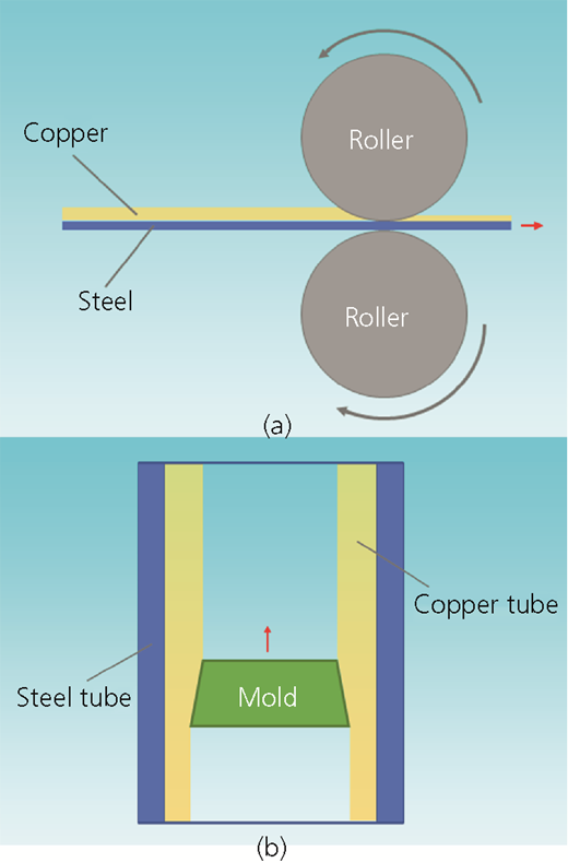
Preparation of copper–steel bimetal composites by the plastic forming method mainly includes rolling, extrusion and drawing processes.22 These processes can make the bimetal composites generate metallurgical bonding between copper and steel through the bimetal composites made of preprocessed copper and steel-based sheets or pipes by plastic deformation.
2.1.2.1 ROLLING
Rolling is a conventional method for preparing copper–steel bimetallic sheets. A schematic diagram of rolling is illustrated in Figure 2(a). The preparation mechanism is such that copper and steel sheets are placed together and suffer plastic deformation by tremendous pressure. Then, the connected surfaces of the two metals are ruptured and activated surfaces are exposed. As a consequence, the interface between copper and steel achieve metallurgical bonding, and copper–steel bimetallic sheets are prepared under enormous pressure.23–27
Schematic diagram of the plastic forming method: (a) rolling; (b) drawing method
Schematic diagram of the plastic forming method: (a) rolling; (b) drawing method
According to the recrystallization temperature, rolling can be divided into hot-rolling, cold-rolling, asymmetrical rolling and vacuum rolling. Moreover, all of the aforementioned methods are required for surface cleaning and roughening.28,29 The contacted surfaces of two metals exhibit characteristics of viscous fluid during hot-rolling. Furthermore, when the contacted surfaces are ruptured and activated metals are exposed, adhesive friction occurs. Ultimately, through the thermal diffusion process, the interfacial bonding of the copper and the steel is generated as metallurgical bonding.
The preparation of copper–steel bimetal composites by the cold-rolling process usually needs more plastic deformation to control the material bonding strength. This is because the rolling temperatures are below the recrystallization temperature. Through the considerable pressure and repeated rolling process, the interfacial bonding between copper and steel become mechanical interlocking and atomic bonding. Moreover, the deformation values of cold-rolling generally reach 60–70%.30,31 Affected by atmosphere at the rolling process, a layer of the oxide film is created at the interface of copper and steel, and this can hinder the diffusion and combination of these two metals. Consequently, some significant improvement of bimetallic interfacial bonding is conducted through the vacuum-rolling process.32–35
Due to lack of sufficient time for diffusion and chemical reaction in the preparation process, parts of copper–steel bimetal composites generate weld points and form metallurgical bonding on the connected surfaces. However, at the interface, some regions are still mechanical bonding so that the bonding strength cannot meet the requirements. Therefore, diffusion annealing is carried out to ensure sufficient copper and steel diffusion during the rolling process. In this case, the interface between copper and steel ultimately forms metallurgical bonds and the bonding strength significantly improves.7,36–45 Also, diffusion annealing can eliminate residual stress and make the work harden during the recovery and recrystallization process. Moreover, diffusion annealing can improve the plastic and processing properties of copper–steel bimetal composites. The annealing temperature is usually in the range 823–873 K, and the holding time is about 1·5 h.46 Wei and Shi47 found that the diffusion range of iron (Fe) atoms is about 25 μm and that of copper atoms is about 10 μm. The average width of the diffusion layer is about 15 μm by the asymmetrical rolling process.47
2.1.2.2 EXTRUSION
Extrusion is a preparation method that is suitable for alloys with poor plasticity and low heat-processing performance. Therefore, this method can be hardly applied to copper–steel bimetal composites with excellent plasticity. Hot extrusion is a standard method for preparing copper–steel bimetallic pipes.48 Because of small deformation resistance for hot extrusion, it always requires a high allowance of deformation and surface roughness. Hot extrusion is usually conducted before the cold-drawing process in the preparation of copper–steel bimetallic pipes.
2.1.2.3 DRAWING
Drawing is mainly used for preparing copper–steel bimetal pipes. As shown in Figure 2(b), it is a preparation method wherein copper alloy pipes and steel pipes are nested together by the substantial plastic deformation generated in both the inner and the outer pipes. Owing to their elastic and plastic characteristics, copper pipes and steel pipes contact closely and achieve metallurgical bonding when mutual diffusion happens in the interface.49–54 Depending on the differences in elastic modulus and processing performance between the outer and inner pipes, necking and expanding processing are generally conducted to prepare copper–steel bimetal pipes. The expanding process is always carried out when the elastic modulus of the outer pipes is lower than that of the inner pipes. Conversely, necking processing is applied. In terms of the drawing process, metallurgical bonding of copper and steel pipes occurring in the plastic deformation process can be divided into three stages.55–60
Stage 1: inner pipe deformation. At the beginning of the drawing process, radial expansion is generated in the inner pipe due to the gap between the inner and the outer pipes when suffering loading. The surface of the internal pipe contacts to the surface of the outer pipe, and then the gap of the two pipes is eliminated. Therefore, no contacted pressure exists in the pipe at this stage.
Stage 2: integration of inner and outer pipes. Affected by the loading, the contacted inner and outer pipes begin to expand synchronously. Elastic deformation and plastic deformation are gradually generated in the outer pipe when the yield condition is achieved. With the loading increasing, plastic sections of the outer pipe extend up to suffer the maximum loading. The integration of two metals occurs at the interface between the inner and outer pipes, and large plastic deformation is generated in the two pipes.
Stage 3: unloading stage. When the maximum load slowly decreases to zero, the inner and outer pipes are in the unloaded state. Because of the difference in elastic modulus between the inner and outer pipes, residual stress exists in the contacted surface and mechanical interlocking occurs in some parts of the two pipes. Diffusion reaction is generated at the interface under a specific temperature. Consequently, the combination of two pipes transforms into metallurgical bonding.
After the drawing process, diffusion annealing can also improve the bonding strength of copper–steel bimetal composites. The effect of the diffusion annealing temperature and annealing time on changes in components was studied in detail; moreover, the interfacial bonding strength of brass–20# steel bimetal composites prepared by the drawing process was also researched.61 The results showed that the interface between brass and 20# steel could achieve good metallurgical bonding by diffusion annealing within specific ranges of temperature and time. With increasing diffusion temperature and time, mutual diffusion also occurred at the interface between brass and 20# steel and the bonding section remarkably increased. It is worth noting that no harmful phase is formed at the interface and the bonding strength can reach 220 MPa. In recent years, copper–steel bimetallic pipes prepared by the mechanical swell shipping method or bulging hydraulic method have gradually become popular. The mechanism of the mechanical swell shipping method or the bulging hydraulic method is similar to that of the drawing method.
2.1.3 Welding method
The welding method is a standard method for the preparation of copper–steel bimetal composites, and it is usually applied in the manufacture of copper–steel bimetallic sheets. The welding method for the preparation of copper–steel bimetal composites mainly includes explosive welding, friction welding and others.62
2.1.3.1 EXPLOSIVE WELDING
Explosive welding was first successfully invited by E. I. du Pont Company in 1957. Figure 3 presents a schematic diagram of explosive welding. It is a sort of welding technology that uses reliable energy produced by explosives to generate high-speed collisions of copper and steel sheets. The oxide films on the contacted surface are destroyed by the transient stress during the collisions. At the same time, the newly cleaned surfaces of the two metals are exposed and form a welding transition layer. The welding transition layer shows the characteristics of plastic deformation, melting, diffusion and waveform. Consequently, copper–steel bimetal composites achieve metallurgical bonding in the welding process. With combination of the rolling process and explosive welding; copper–steel bimetal composites show a better performance.63–65
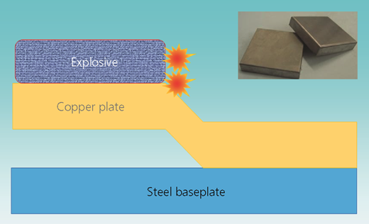
This method has advantages of excellent bonding strength and is suitable for high-dimensional precision products. Compared with other bimetal composite technology, it is an economic preparation method wherein the equipment for explosive welding is simple and easy to operate. However, because of the presence of explosives being detonated simultaneously during the explosion process, the method can be applied to prepare copper–steel bimetal composites with small sizes only. Moreover, application and popularization of explosive welding are restricted because continuous mechanization production cannot be carried out and higher environmental pollution results from the explosives.66–71
2.1.3.2 FRICTION WELDING
Copper–steel bimetal composites prepared by friction welding usually utilize torque and pressure. Then, immense friction heat is created at the contacted surfaces of the two metals and is produced by relative displacement of copper and steel. Subsequently, the surrounding areas of the contacted surface reach the viscoelastic state and mechanical interlocking is caused by deformation heat and plastic flow. As a consequence, mutual diffusion and recrystallization of bimetals occurs at the interface. Ultimately, the interfacial bonding of copper–steel bimetal composites transforms into metallurgical bonding. This method is very suitable for dissimilar materials that show the characteristics of short-time processing, non-welding embrittlement and high bonding strength.1–3 It is worth noting that torque and pressure, which are the two critical parameters for the friction welding process, have an essential influence on the bonding strength of copper–steel bimetal composites.
2.2 Solid–liquid method
The solid–liquid method is a sort of method in which one of the raw materials is in the liquid phase and another one is in the solid phase in the preparation process. It mainly includes the traditional casting method, reverse solidification method and continuous casting/rolling method.72–85
2.2.1 Traditional casting method
The preparation of copper–steel bimetal composites by the casting method is generally carried to cast molten copper alloys directly into the steel molding because the liquid phase temperature of steel is higher than that of copper.86–89 This method shows the advantages of being a simple manufacturing process and low cost and is hardly affected by the shape of the casting molding.
In terms of dissimilar metals such as copper and steel, it is a challenge to generate metallurgical bonding through mutual diffusion of molten copper alloys and steel molding. Therefore, some procedures for increasing the activity of atoms are conducted through the removal of the oxide layer or plating a copper coating on the surface of the steel mold. Lead alloy or lead bronze and steel molding are generally heated in the range 1223–1323 K in the copper casting process, wherein the temperature is close to the melting point of the copper lead alloy (1373–1573 K). The purpose of the rapid diffusion of the steel and the copper is achieved through the activation of borax in the casting molding.
2.2.2 Inverse solidification method
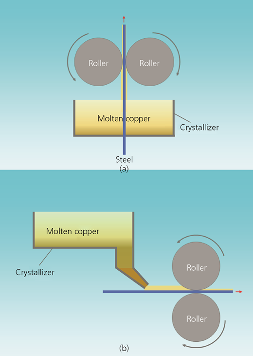
The inverse solidification method is a new steel-belt preparation technology developed by the Germany DMS Company in 1989.90,91 The method in Figure 4(a) shows that steel sheets or wires cross through molten copper alloys in a crystallizer of inverse solidification. The molten copper alloys rapidly solidify around the steel sheets or wires for preparation of copper–steel bimetallic sheets or wires.92,93 Due to the outward solidification direction of the surface of steel sheets or wires in the solidification process, the method is called an inverse solidification method.
Schematic diagram of the solid–liquid method: (a) inverse solidification method; (b) continuous casting/rolling method
Schematic diagram of the solid–liquid method: (a) inverse solidification method; (b) continuous casting/rolling method
At the initial stage, the interface layer of copper and steel is thin; with solidification, the interface forms metallurgical bonds through the forceful contacting induced by interfacial wetting. The formation of copper–iron solid solution is accompanied by the process of mass transfer, heat transfer and mutual diffusion.7,90–95 Compared with the rolling method and explosive welding, the inverse solidification method exhibits the characteristics of high efficiency, low energy consumption, continuous manufacture and short production process, whereas its disadvantages are difficult operation, flat qualification rate and tricky control of the dimensional precision.
Studies on copper–steel bimetallic sheets or wires prepared by the inverse solidification method are gradually increasing in recent years. Some scholars have researched the inverse solidification process of copper–steel bimetallic wires.96,97 They successfully prepared copper–clad steel wires wherein the interface is metallurgically bonded. The preparation was carried out through detailed procedures in which the raw materials of molten copper alloys flowed from a melting furnace to a crystallizer. Then, the steel wires were preheated after surface treatment at a specific temperature. Subsequently, immersion wetting, adhesion, nucleation and solidification of molten copper alloys occurred at the contacted surfaces of copper and steel in the preparation process. The studies also showed that the ratio of the cladding layer was related to the immersion time of steel wires and reached the maximum value when the interface is at thermal equilibrium conditions. The temperature of molten copper also has an impact on the ratio of the cladding layer. When molten copper alloys are at high temperatures, the ratio is smaller. Conversely, lower temperatures of molten copper alloys result in a higher ratio.
2.2.3 Continuous casting/rolling method
The continuous casting/rolling method can solve problems with the casting process. This method can improve the bonding strength and application performance. Combining the casting and rolling processes, as illustrated in Figure 4(b), the continuous casting/rolling method for preparing bimetal composites has developed a modern preparation technology. The method involves casting molten copper alloys into transferring steel belts or sheets continuously in the conveyor, and then the molten copper solidifies rapidly through the chilling effect. During the solidification process, cast copper alloys in the semisolid state are rolled with steel belts or sheets by the rolling machine. In this process, metallurgical bonding is generated by the copper in the semisolid state and the steel in the solid state. It is the same as the inverse solidification method. In general, to improve the wetting ability of molten copper alloys and prevent the oxidation of steel belts or sheets, the continuous casting/rolling process is often conducted in a protective atmosphere. The steel belts or sheets are usually perpetrated by copper coating to improve the bonding strength and achieve outstanding comprehensive properties.
The solidification of molten copper alloys can be divided into two stages at the continuous casting/rolling process.34,35 First, when the molten copper alloy is cast into the preheating steel belts or sheets, spherical semisolid copper is formed and is rolled together with steel. Second, the semisolid copper alloy flows and is aggregated in the rolling process. The nucleation grain is deformed by suffering the rolling pressure, and the solidification speed of semisolid copper alloy also accelerates, affected by the rolling pressure and the heat transformation. In this case, metallurgical bonding is generated and copper–steel bimetallic composites with excellent performance are ultimately prepared.
2.3 Liquid–liquid method
The liquid–liquid method uses raw materials of copper and steel in the molten state or liquid state in the preparation process.98–107 The method belongs to the category of casting technology, which mainly includes the molding transformation method and double-molten-metal method. The advantages of this sort of method are low cost and highly productive. However, subsequent mechanical processing is needed for complex work blanks with a lower qualification rate.
2.3.1 Molding transformation method
As shown in Figure 5(a), the molding transformation method involves casting molten copper and steel into the transformed molding separately in the preparation process. In this case, the two metals are not cast into the same mold cavity, but drop into the different top casting boxes at the twice casting processes. The method can be directly observed in the solidification state of the former molten metal. Then, another molten metal is cast based on the state of the former metal. Therefore, the ‘mixing’ phenomenon of two metals does not occur during the casting process.96,97 The advantages of the method are that it avoids non-effective casting time and ensures metallurgical bonding at the solidification process. The thickness of the interfacial layer of copper and steel is uniform, and the specific shape of the contacted surface can be manufactured by using copper–steel bimetallic blanks. As a consequence, the interface of bimetal composites is no longer confined to the plane. Nevertheless, it requires higher technology and the operation is comparatively more difficult.
Schematic diagram of the liquid–liquid method: (a) molding transformation method; (b) double-molten-metal method
Schematic diagram of the liquid–liquid method: (a) molding transformation method; (b) double-molten-metal method
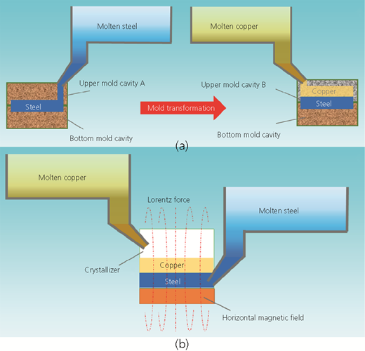
2.3.2 Double-molten-metal method
The double-molten-metal method is a method wherein two molten metals are cast into a crystallizer from different entrances. The Lorentz force, which is created by the horizontal magnetic field device in the bottom of the crystallizer, affects the molten metals and crosses vertically into the horizontal magnetic field. Figure 5(b) presents a schematic diagram of the double-molten-metal method. The convective mixing of two molten metals is inhibited by the Lorentz force at the preparation process. Affected by the Lorentz force, the crystallizer can be divided into two sections, where the demarcation line is divided based on the horizontal magnetic field force. Ultimately, copper–steel bimetal composites are completely prepared during the cooling and solidification process.102–107
3 Applications of copper–steel bimetal composites
Up to now, more and more copper–steel bimetal composites have been applied in the industry and modern life. According to the shape of the copper–steel bimetal composites, they can be classified as copper–steel bimetal sheets, wires, tubes and other engineering structure components.108 Significantly, sheets are the most widely used among copper–steel bimetal composites.
3.1 Copper–steel bimetallic sheets
The applications of copper–steel bimetallic sheets mainly include bearing bushes, molding guide plates, cooling staves and cartridge cases.107–109
3.1.1 Bearing bushes
Bearing bushes are one of the most important parts of a diesel engine. They usually require properties of anti-fatigue resistance, wear resistance, anti-adhesion, corrosion resistance and high-temperature resistance. The material performance has a direct relationship with the safety of the diesel engine. In general, copper–steel bimetal composites or even triple-layer metals are mostly used in bearing bushes in high-power diesel engines. With the development of the industry, bearing bush materials have also been rapidly developed and extensively researched. In 1839, the Babbitt alloy appeared and became widely used in bearing bush materials. Then, in 1870, the cold-pressed sintered oil-bearing bush was invented in the USA. In 1910, the sintered bronze bearing bush (73 wt.% copper, 13 wt.% tin, 10 wt.% lead, 4 wt.% graphite and 5% oil rate) was first manufactured in Germany and commercialized by GE Corp. In the 1950s, the Babbitt alloy, copper lead alloys and aluminum alloys had been extensively applied in sliding bearing bush materials. Up to the 1990s, these had been commonly used in high-tin aluminum–steel bimetals for bearing materials in the automobile and tractor industry.110–113 However, all of these materials have the common disadvantages of low fatigue strength, low bearing capacity and poor wear resistance.114
Copper–steel bimetal composites showing high fatigue strength, high bearing capacity and high working temperature have been of significant concern to many researchers. As the ideal bearing bush material, copper–steel bimetal composites have been used in industries, transportation, aerospace and other fields.115–118Figure 6 presents the different kinds of copper–steel bimetal bearing bushes. The figure shows copper–steel bimetal composites, which are composed of QCuPb24Sn1 and steel plate cold rolled commercial steel sheets. Their advantages include compact structure, convenience of preparation, small occupied volume and high utilization rate.119
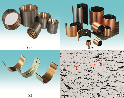
Bearing bushes: (a–c) copper–steel bimetal bearing bushes; (d) microstructure of graphite/copper composites
Bearing bushes: (a–c) copper–steel bimetal bearing bushes; (d) microstructure of graphite/copper composites
In recent years, the international standard ISO 4383120 included a clause:121 the use of lead would be limited to making specific materials in the future. It is because lead is harmful to the environment and human health. Some countries and regions have restricted the use of lead-containing bearing bush materials and started to study bearing bush materials without lead.122,123 Some scholars researched copper–steel bimetal composites composed of an appropriate amount of aluminum (approximate 6 wt.%) to substitute for lead.124,125 Their results showed that lead-free copper–steel bimetal composites efficiently reduced the friction coefficient and improved the wear resistance. The lubricating phase of the composites has transferred from lubricating oil to the solid lubrication. Studies show that composites with solid lubrication have excellent friction performance that allows them to be used in some special conditions, such as high temperature, low temperature, high vacuum and intense radiation. In recent years, graphite substituting for lead as lubrication was studied by Du et al.98,99 They found the composites expressed excellent performance.98,99 Due to the significant difference between graphite and copper in physical properties, graphite particles are prone to float and aggregate on the upper part of the molten copper alloy during the casting process. Therefore, it is a challenge to fabricate uniformly dispersed graphite composites under stable convection conditions. Methods including powder metallurgy, liquid impregnation, spray deposition and semisolid formation are studied to avoid graphite segregation in graphite/copper composites. Figure 6(d) presents the uniform distribution of graphite/copper composites prepared by powder metallurgy. Moreover, molybdenum disulfide (MoS2), tungsten disulfide (WS2) and tungsten diselenide (WSe2) were also used as substitutes for the element lead as solid lubricants by some researchers.126 As a consequence, the copper alloy in copper–steel bimetal bear bush materials exhibited excellent antifriction and wear resistance properties through the self-lubricating effect. The steel component in copper–steel bimetal is needed for superior mechanical properties, enough bearing capacity and good processing performance. In the past years, copper–steel bimetal bearing bushes have been widely substituted for cast copper, high-tin aluminum alloys, Babbitt alloy and other traditional materials.
The primary preparation method of copper–steel bimetal bearing bushes is the powder metallurgy method.119 Wu and Wang119 prepared copper–steel bimetal composites that were composed of a steel sheet (0·04–0·08% carbon, 35% elongation) and CuPb24Snl alloy. The results showed that this can efficiently solve the contradiction between hardness and density. Moreover, the studies also improved the preparation by twice sintering, annealing process and three-time rolling. Zhang et al.127 successfully fabricated graphite/copper–steel bimetal composites by using semisolid strip casting and rolling technology. The technology improved traditional solid–liquid casting/rolling and successfully uniformly synthesized semisolid copper matrix slurry containing 10 vol% graphite and 10 vol% silicon carbide (SiC) particles. The method efficiently solved the segregation problem and improved bonding strength. The interfacial shear strength reached 140 MPa and increased by 50% compared with powder metallurgy and rolling method.
3.1.2 Molding guide plates
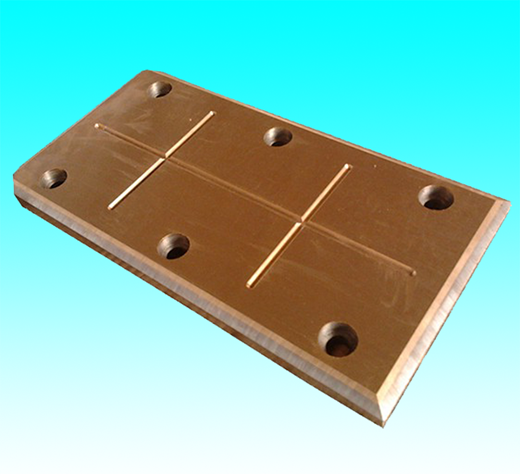
Molding guide plates are a critical guiding and positioning component in the molding. At present, molding guide plates are usually made from copper alloys prepared by powder metallurgy. The requirement of the molding guide plate in a car cover molding is substantial, and the average dosage of the copper alloy is about 20–30 kg for each molding.103 Due to the impact of the abrasion effect on the orientation process, repair of molding guide plates is difficult and results in enormous copper waste. Combination of excellent wear-resistant performance of copper alloy and good mechanical properties of steel and copper–steel bimetal composites can significantly reduce the consumption of copper alloy and efficiently improve the performance. Copper–steel bimetal molding guide plates are usually prepared by extrusion, forging, rolling or powder metallurgy method. Figure 7 shows a copper–steel bimetal molding guide plate. The molding guide plate made of copper–steel bimetal composites is an excellent way to improve a service life. Generally, the copper part of a copper–steel bimetal molding guide plate is made of bronze, lead bronze and aluminum bronze; moreover, the steel parts used are always low-carbon steel with excellent anti-impact properties.
In recent years, medium or large stamping die guide plates in the automobile molding industry are usually made of copper alloy or copper–steel bimetals prepared by powder metallurgy. However, modern materials and preparation methods still cannot meet the requirements of production. The criteria of performance are high precision and high strength for molding guide plates in the future. Zhang et al.103 developed a new copper–steel bimetal molding guide plate composed of a high-strength copper alloy (Cu–Zn23–Al5·5–Fe4–Mn4·5) and T10 steel. The bimetal composite was prepared with molten copper alloy and pretreated T10 steel plate.103 Due to mechanical bonding, fusion bonding and diffusion bonding, copper–steel bimetal molding guide plates have a high strength interface. The liquid–solid rolling technology has the advantages of high efficiency and low cost. The technology achieving continuous production has excellent development and application prospects. In the future, the liquid–solid rolling technology will develop a mainstream method for the preparation of copper–steel bimetal molding guide plates.
3.1.3 Cooling staves
Copper alloys have the advantages of excellent thermal conductivity (pure copper: 377 (W/m)/K, 373 K), thermal stress characteristics and thermal shock resistance and are widely used as cooling staves in a blast furnace, as shown in Figure 8(a). Copper cooling staves are usually made through the rolling or casting method. Figure 8(b) shows a cast-iron cooling stave, which is also widely used in many fields. However, due to their high cost and low strength, copper or cast iron restricts the development of cooling staves. The solution is copper–steel bimetal composites made of copper alloys with good thermal conductivity and steel with excellent mechanical properties, shown in Figure 8(c). These can save costs and enhance the mechanical performance of cooling staves. Some scholars compared copper cooling staves and copper–steel bimetal cooling staves by computer simulation.128 The results showed that there are no remarkable differences between them. Moreover, compared with ductile cast-iron cooling staves, copper–steel bimetal cooling staves exhibited a lower fluctuation range under lower temperatures in real conditions.
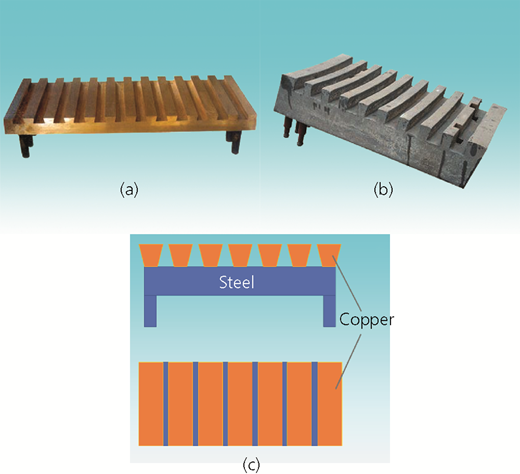
Cooling staves: (a) copper cooling stave; (b) cast-iron cooling stave; (c) copper–steel bimetal cooling stave
Cooling staves: (a) copper cooling stave; (b) cast-iron cooling stave; (c) copper–steel bimetal cooling stave
Semisolid casting with low cost and high efficiency is an effective method for preparing cooling staves. However, microcracks quickly appear on the interface of copper–steel bimetal cooling staves during the rolling process. This is because the size of cooling staves is huge and there is a significant difference between the plastic moduli of copper and steel. Therefore, the rolling method is not suitable for the preparation of copper–steel bimetal cooling staves. Friction welding and explosive welding are not ideal for the preparation of copper–steel bimetal cooling staves.
3.1.4 Cartridge cases
In recent years, a research hotspot is the investigation of the potential of copper–steel bimetal composites to substitute brass cartridge cases. Copper–steel bimetal cartridge cases show excellent ballistic performance and can save many raw materials. Cartridge case materials have the structure of a thin wall and a thick bottom, which can be prepared by drawing process. Some scholars researched the drawing process preparation of copper–steel bimetal cartridge cases. The results showed that cartridge cases made of copper–steel bimetal composites were successfully manufactured by the three-time drawing process. Annealing is always conducted after the drawing process because work hardening, uneven plastic deformation and high residual stress are often generated.129 Moreover, a cartridge case with a three-layer structure was also successfully fabricated from copper–steel bimetal composites. The cross-section of the cartridge case with a three-layer structure was made of brass (inner layer), brass (middle layer) and steel (outer layer), and its volume ratio was about 15:80:5. The copper–steel bimetal cartridge case consisted of 20 steel sheets and H68 brass and had the advantages of functional plasticity and low strength.
3.2 Copper–steel bimetal pipes and wires
Many countries have started to research and develop copper–steel bimetal pipes and wires intensely since the past century. Up to now, copper–steel bimetal composites have been widely used in many fields, such as the machinery, energy and chemical shipping industries.130–133 Copper–steel bimetal pipes are known as copper–steel duplex tubes or copper–steel clad pipes and are mainly used as gas or liquid pipelines and condenser pipes. Copper–steel bimetal wires (copper–clad steel wires) are primarily used as conductive wires in the electronic communication, transportation and construction industries.
3.2.1 Gas/liquid pipelines
Since the 1950s, studies on and manufacture of copper–steel bimetal tubes have experienced fast development in the world. Gas pipelines usually transfer coal gas, natural gas, petroleum and other corrosive substances in real conditions. Therefore, raw materials of copper–steel bimetal tubes are always made of pipeline steel or carbon steel, which is coated with copper–zinc alloy in the inner layer. In terms of marine oil (gas) pipelines, due to erosion in the sea, marine pipelines are usually made of stainless steel with excellent corrosion resistance. The diameters of bimetal pipelines have the full range 0·8–1400 mm, and the thickness of the pipes is 0·15–70 mm; therefore, the width of the copper component is approximately 5–50% of the total thickness.134
Copper–steel bimetal pipes have the features of good thermal conductivity, antifriction properties and excellent wear resistance. The pipes are used in high-speed and high-load conditions, such as those in large internal combustion engines, steam turbines, various pump cylinder guide sleeves and granular material pipelines. Moreover, copper–steel bimetal pipes show excellent compressive strength, creep resistance, anti-fatigue strength and anti-corrosion in the oil under the bearing operating temperature.
3.2.2 Condenser pipes and heat-exchange equipment
Copper–steel bimetal tubes have been widely used in seawater coolers and refrigeration and heat-exchange equipment. The copper parts usually use copper–nickel (Ni) alloy, which requires high-temperature resistance and corrosion resistance. The excellent corrosion resistance and thermal conductivity ensure that copper–steel bimetal tubes function in the heat exchanger of a nuclear reactor. Copper–steel bimetal tubes can withstand tremendous stress and failures cannot occur at the high cold and the hot alternation state.
3.2.3 Conductive cables and springs
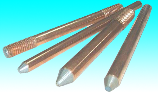
Copper–steel bimetal conducting cables are the newest materials used in the electrical and electronic communication industry in recent years. Figure 9 presents a production of copper–steel bimetal conductive cables. Traditional cables are usually manufactured with pure copper or copper alloy. However, copper–steel bimetal cables, which are made of pure copper and stainless steel, ensure conductivity and corrosion resistance. Copper–steel bimetal cables can also increase strength and reduce the thickness of the cables.
Conductive springs made of phosphor bronze and beryllium (Be) bronze have the disadvantage of high cost. The elasticity of conductive springs usually decreases with increasing conductivity.135 In this case, some scholars studied copper–steel bimetal conductive springs made by gravity casting.136 Copper–steel bimetal conductive springs made of electrolytic copper and low-carbon steel exhibit excellent elasticity and conductivity, and they can also reduce cost. In the future, copper–steel bimetal conducting wires and springs have a grander prospect for their excellent electrical conductivity and low price. Bimetal composites are superior to copper alloy conducting wires and springs and hold great promise to substitute for modern materials.
3.3 Other applications
3.3.1 Hydraulic pumps
Three friction pairs (cylinder and oil distribution disk, piston and slipper, slipper and retainer plate) have become main factors that limit the performance of hydraulic pumps. Copper–steel bimetal composites can significantly improve the performance of those three friction pairs.
The traditional hydraulic pump cylinder materials are seamless steel pipes that are manufactured by forging, casting, rough boring, semi-fine boring, beautiful boring (plating), polishing and many other procedures. However, seamless steel pipes show the characteristics of low efficiency and high cost. As shown in Figures 10(a) and 10(b), a copper–steel bimetal hydraulic pump cylinder was prepared by casting. It consists of a steel substrate and copper–lead alloy. Figures 10(c) and 10(d) present pistons and slippers made of copper–steel bimetal composites. Sometimes, stainless steel–steel bimetal composites are used for hydraulic pumps under conditions with water as the medium.
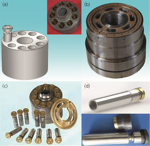
Hydraulic pumps: (a, b) hydraulic pump cylinders; (c, d) hydraulic pump pistons and slippers
Hydraulic pumps: (a, b) hydraulic pump cylinders; (c, d) hydraulic pump pistons and slippers
Up to now, the biggest problem of copper–steel bimetal pistons and slippers is lead segregation and defect generation in the process. Moreover, the low bonding strength and the failure of copper–lead alloys are also issues in the future. The utilization rate of materials is only 60–70%. Studies on the combination of copper and steel, the precipitation and segregation mechanism of lead and the improvement of bonding strength and mechanical properties were conducted by many researchers. Some scholars studied the new preparation and improved casting and heat treatment techniques.137 The results showed that the microstructure became compacted by modification with rare earths and lead segregation was also enhanced. Moreover, the hardness and wear resistance of copper–steel bimetal composites were remarkably improved. Chen et al.36 successfully solved lead segregation by using 35# steel or 45# steel and copper lead alloy powder.
Other preparation methods, such as diffusion welding, easily cause lead segregation, increase hardness abnormally and reduce the cutting performance. Some scholars have solved the aforementioned problems. They sintered copper matrix antifriction alloy containing the elements tin, lead and nickel by powder metallurgy and then fabricated copper–steel bimetal composites by diffusion welding with 45# steel.31
Wang and Tian31 researched advanced hydraulic pumps for use in the aerospace field. The results showed that copper–steel bimetal composites are prepared by hot isostatic pressure diffusion connection technology and clean isolation technology. These technologies can eliminate the defects of the variant interface and ensure the reliability of the interfacial connection. The bonding strength of the specially shaped surface was also increased. Copper–steel bimetal composites have been successfully used in the production of the hydraulic pump pistons in the aircraft field and will be generalized to civilian products in the future. Moreover, the copper–ductile iron bimetal is also gradually generalized to hydraulic pump materials.138
3.3.2 Engineering structural components
Engineering structural components (such as train pantographs and switch sliding baseplates) made from copper–steel bimetallic composites have been studied in recent years.139–145 Copper–steel bimetallic composites are believed to replace existing materials in the future gradually.
4 Expectations
The emergence of copper–steel bimetal composites has undoubtedly substituted many traditional materials in different fields. However, production and research are still facing many problems. As a consequence, the following points are proposed to be researched in the future.
Nowadays, more and more countries intensively research copper–steel bimetal composites for better corrosion resistance and antifriction. In the future, the preparation of copper–steel bimetal composites will be developed toward diversification, which is composed of several traditional preparations. Composite moldings will have improved efficiency, low cost and environmental protection. Moreover, energy saving and environmental protection are the key to the fabrication process. How to solve the pollution and save the energy become the points in the future.
In the future, the development of the copper–steel bimetal composites serving under harsh conditions, such as high temperature, high pressure, high strength and high corrosion, will become the inevitable trend. Moreover, copper–steel bimetal composites with high performance and low cost will play an essential role not only in the traditional fields, such as bearings, hydraulic pumps and oil/gas pipeline applications, but also in many frontier technologies, such as aerospace, deep-sea exploration, super high-speed railways and military.
Acknowledgements
This work was supported by the National Natural Science Foundation of China (51805408); the Science and Technology Project of Guangzhou City in China (201604046009); the Natural Science Foundation of Shaanxi Province of China (2018JM5002); the Science and Technology Project of Guangdong Province in China (2015B010122003, 2015B090926009); the Guangxi Innovation-Driven Development Project (GUIKEAA18242001); and the Fundamental Research Funds for the Central Universities of China.
