
The deregulation of the power market and the growing reliance on electricity generation from variable renewable energy sources have significantly altered the operational dynamics of hydropower plants. The shift from hydropower systems designed to function as base load plants to pumped storage schemes (PSPs) characterised by more frequent load changes and start/stop sequences of operations significantly increased the relevance of transient conditions with respect to static ones. While existing research has predominantly focused on the effects of water pressure on tunnel linings under steady-state conditions, little to no attention has been given to transient conditions. This paper addresses this gap in the current literature by presenting a novel model for evaluating the behaviour of reinforced concrete linings in hydraulic tunnels during transient conditions. This approach allows for a comprehensive understanding of the intricate interaction between fluid flow, tunnel structure, and rock mass. The insights gained have the potential to significantly advance the assessment and safeguarding of the structural integrity of hydraulic systems operating in PSPs.
Notation
flow area through the gap
change in gap volume due to the lining radial displacement caused by a unit variation of differential pressure
change in gap volume due to the rock mass radial displacement caused by a unit variation of water pressure
diameter of the holes in the lining
radial gap between the lining and the rock mass
lining elastic modulus
elastic modulus of the rock mass
gravity acceleration
water bulk modulus
lining permeability
inverse of the fraction of water pressure carried by the rock mass
tensile axial force in the lining during a transient event
tensile axial force in the lining in steady-state conditions
number of holes in the lining across the circumference
water pressure outside the lining during a transient event
steady-state water pressure inside the tunnel
water pressure inside the tunnel during a transient event
flow rate across the lining
flow rate across the rock mass
lining average radius
radius of tunnel excavation
spacing of the hole in the lining along the tunnel axis
lining thickness
gap volume
flow velocity through the gap
head loss due to the flow through the lining
timestep used in the transient analysis
variation of the volume of the gap due to lining and rock mass displacements
variation of the volume of the gap due to water compressibility
variation of the volume of the gap due to flows
radial displacement of the lining
radial displacement of the rock mass excavation boundary
Poisson coefficient of the rock mass
head loss coefficient
water density
1. Introduction
To enhance waterways hydraulics and stability, concrete linings are commonly employed in hydraulic tunnels. These linings are often reinforced to prevent cracking and enhance durability (EPRI, 1987). The design of these linings must consider both geomechanical and hydraulic loads, including internal and external water pressures. When the external pressure surpasses the internal pressure, such as during system emptying, the lining is subjected to compressive stress. Conversely, if internal pressure exceeds external pressure, such as during system filling, the lining will experience tensile stress.
External water pressure is primarily influenced by the groundwater level within the surrounding rock, while internal water pressure is affected by the plant’s operation. When the plant operates with a constant flow, the internal pressure reaches a steady-state value. However, fluctuations in flow lead to oscillating transient pressures.
Transient pressures can exceed the tensile strength of the concrete lining, leading to potential cracking and increased seepage. Frequent oscillations in pressure may also induce fatigue issues in the lining.
Fatigue verification is a standard practice for steel-lined hydraulic tunnels (Cerjak et al., 2015; Hammer and Maldet, 2014; Pachoud, 2017). Some research has addressed fatigue related to geomechanical factors, particularly in unlined tunnels exposed to transient pressures, and introduced the concept of hydraulic fatigue (Lang et al., 1976; Neupane et al., 2020, 2021; Neupane and Panthi, 2018, 2021; Panthi, 2012). This is relevant given the documented increase in rock falls in tunnels subject to frequent load changes (Bråtveit et al., 2016).
In contrast, fatigue aspects are often overlooked or dismissed in practice for concrete structures in hydropower plants. This approach is generally acceptable for hydropower systems originally designed as base load plants to provide a continuous electricity supply year-round, given the infrequent occurrence of internal water pressure fluctuations. However, with the rise in variable renewable energy sources and deregulation of the power market, the adoption of pumped storage schemes (PSPs) for grid stabilisation (Catrinu et al., 2011) has significantly altered the operational dynamics of hydropower plants. This change has increased load variation frequencies, leading to more unsteady flow and pressure transients. Therefore, considering fatigue-related aspects of reinforced concrete linings in response to these transient conditions is becoming increasingly crucial in the structural design of hydropower plants.
The behaviour of hydraulic tunnel reinforced concrete linings during transient events cannot be addressed with the approaches found in existing literature (Bobet and Nam, 2006; Fernandez, 1994; Fernandez and Alvarez, 1994; Schleiss, 1986a, 1986b, 1997; Zareifard, 2018), which cover cases characterised by a slow rate of internal pressure change, such as those experienced by tunnels during filling operations (2–10 m/h, according to Rancourt, 2010) where steady-state conditions can be assumed. For much faster phenomena like transient events, where water pressure changes reach values on the order of 100 m of water column per second in larger plants, the effects of these transient events play a significant role and must be properly considered.
To address this gap in the literature, the hydromechanical interaction between the lining and the rock mass under steady conditions was first examined (Stucchi, 2024), focusing on two critical factors influencing the response of reinforced concrete: the potential formation of a water-filled gap between the lining and the rock mass, and the progressive cracking of the lining. These factors are essential for establishing realistic initial conditions for subsequent transient events, particularly regarding the lining’s stiffness.
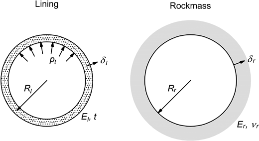
Building on this foundation, the present study investigates the response of linings during transient events. It specifically examines the mechanical and hydraulic interactions that arise during rapid pressure changes, offering a comprehensive framework for understanding their behaviour under non-steady conditions. The analysis is based on the following assumptions (Figure 1): (a) the rock mass behaves elastically, (b) the lining behaves elastically, and (c) the tunnel cross-section is circular, enabling the use of axisymmetric conditions.
The axial symmetry of the system neglects any stress changes resulting from alterations in the bending moment caused by rock mass displacements. This assumption is considered reasonable, as the stress change associated with this phenomenon is deemed minimal in comparison to other factors.
The approach is presented for the case in which the rock mass can be assumed impervious during the transient event, such as in the case of rapid pressure changes, particularly in low-permeability rock masses. However, the equations can be easily adapted to the more general case where water exchange also occurs through the rock mass.
The approach is based on a model that simulates the complex interplay of mechanical and hydraulic factors within the lining–rock interaction. Based on the time evolution of internal pressure, the model enables the determination of the time evolution of the tensile axial force in the lining under transient conditions, thereby providing a basis for the fatigue verification of these reinforced concrete structures.
When defining transient solicitations, it is important to distinguish between linings that remain impervious during transient events and those that behave as drained even under transient conditions. Section 2 addresses the former, while Section 3 discusses the more complex interplay of mechanical and hydraulic factors for pervious linings. Applications of the developed model are presented in Section 4.
2. Impervious linings
Depending on the rate of internal pressure change, a lining that is considered drained under steady-state conditions can be treated as impervious during transient conditions if negligible water flow occurs through it. Under this assumption, the lining–rock mass interaction can be determined solely through mechanical considerations. By imposing that the lining radial displacement () must be equal to the rock mass radial displacement () during the transient event, the following equations can be applied:
where is the tensile axial force in the lining during the transient event (variable in time); is the tensile axial force in the lining in steady-state conditions; is the internal pressure during the transient event (variable in time); is the internal pressure in steady-state condition; is the lining’s average radius; is the lining’s elastic modulus; is the lining thickness; is the rock mass’ elastic modulus; and is the rock mass’ Poisson coefficient. Given the transient nature of the phenomena, some of the quantities in the above equations are referenced to time .
The above equations are applicable when the lining is in direct contact with the rock mass. They can also be considered valid in the presence of a water-filled gap between the lining and the rock mass, provided the rock mass can be assumed impervious during the transient event, such as in the case of rapid pressure changes, particularly in low-permeability rock masses.
These equations are derived by assuming that the lining can be treated as a thin-walled cylinder (Fernandez, 1994). While this might not perfectly mirror actual behaviour, it is worth noting that this assumption is considered reasonable due to the inherent uncertainties associated with the parameters involved, particularly those concerning the rock mass.
The stress state in the lining under steady-state conditions () serves as an input for Equation 1 and must be evaluated by accounting for both the static internal water pressure () and the geomechanical loads caused by tunnel excavation. Steady-state conditions can lead to either compressive or tensile stresses in the lining, making it crucial to carefully define the sign of . Transient conditions superimpose additional stresses onto the steady-state stresses, further affecting the stress state in the lining. As indicated in the previous equations, an internal pressure exceeding the steady-state value () induces tensile stresses or reduces compressive stresses in the lining, while an internal pressure below the steady-state value leads to compressive stresses or a reduction in tensile stresses.
It is important to note that during the transient, the lining experiences only a portion of the internal pressure variation due to a load-sharing phenomenon with the rock mass. This phenomenon is governed by the relative stiffness between the lining and the rock mass, represented by the ratio in Equation 2. In the case of a reinforced concrete lining, its stiffness is determined by the presence of cracks. Cracks can form both during construction, due to shrinkage effects, and during plant filling. Consequently, a thorough understanding of the cracking process is essential for accurately estimating the lining stiffness, to avoid overestimating or underestimating the transient solicitations (Stucchi, 2024). Similarly, careful attention must be given to defining the stiffness of the rock mass, which may be reduced by excavation activities. This reduction in rock mass stiffness increases the portion of the internal pressure variation borne by the lining.
3. Pervious linings
In linings that have undergone cracking or are equipped with drains, water flows through the lining can be relevant. In such cases, the lining behaviour can be treated as drained even in transient conditions. This makes determining the transient response becomes more complex, as hydraulic aspects must be considered alongside mechanical ones. Flows through the lining during transient events can reduce, sometimes significantly, the differential pressure acting on the lining.
Due to the lack of relevant investigations in the literature, a dedicated model has been developed to reproduce the lining–rock mass behaviour under these conditions. This model simulates the complex interplay of mechanical and hydraulic factors in the lining–rock mass interaction, assuming the presence of a thin layer of water (gap) existing between them (Figure 2).
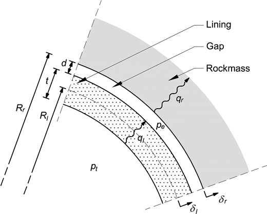
Model for the simulation of the lining–gap–rock mass system behaviour during transient events
Model for the simulation of the lining–gap–rock mass system behaviour during transient events
As highlighted by Stucchi (2024), the conditions for gap formation are prevalent in practically every situation encountered in practice. In the absence of gap, the interaction between the lining and rock mass reduces to a purely mechanical problem governed by the equations presented in Section 2.
The model aims to assess the variation in tensile axial force within the lining () during a transient event, specifically a change in water pressure in the tunnel (). During this transient event, the water pressure in the gap () does not immediately follow the changes in tunnel water pressure, creating a differential pressure and, consequently, an axial force within the lining. Therefore, it is crucial to evaluate the time evolution of the water pressure in the gap throughout the transient event. To achieve this, the model uses an explicit time integration scheme, discretising the transient duration into small timesteps (). To ensure numerical stability, a timestep on the order of milliseconds is used. The details of this procedure will be presented in the current section.
Assuming that the water density remains constant, the continuity equation applied to the gap can be expressed as follows:
where denotes the change in volume over the timestep due to the displacements of the lining and the rock mass; denotes the change in volume over the timestep due to the water flows through the lining and the rock mass; denotes the change in volume over the timestep due to the change in the gap water pressure.
This equation must be satisfied throughout the entire duration of the transient. The three components of Equation 3, which account for the mechanical aspects, hydraulic aspects, and fluid compressibility, will be explained in detail in the following sections.
3.1 Mechanical aspects
The mechanical behaviour of the lining is simulated by modelling it as a thin-walled cylinder. Under this assumption, the radial displacement of the lining can be expressed by the following equation:
where is the radial displacement of the lining (positive if outwards; Figure 2), is the water pressure in the tunnel at time , is the water pressure in the gap at time , is the lining’s average radius, is the lining’s elastic modulus, and is the lining thickness.
As evident from Equation 4, the elastic modulus of the lining contributes to the lining’s response during a transient event. Hence, accurately determining its value is essential for faithfully replicating the lining behaviour. Overestimating the number of cracks in the lining leads to reduced stiffness and, consequently, an underestimation of the forces in the lining. Detailed insights into this aspect are presented by Stucchi (2024).
The radial displacement of the excavation perimeter at time , denoted as , can be quantified using the following equation, which assumes an elastic behaviour of the rock mass:
where signifies the radius of tunnel excavation, denotes the elastic modulus of the rock mass, and represents the Poisson coefficient of the rock mass. The equation above assumes the constancy of the groundwater level throughout the transient event, a reasonable assumption given the rapid nature of such events.
Equations 4 and 5 can be combined to determine the change in volume due to the displacements () over the timestep :
3.2 Hydraulic aspects
In addition to the mechanical aspects, hydraulic factors also affect the system’s response to a transient event. Water flows entering the gap from the tunnel () or exiting the gap to the rock mass () can partially or completely offset the gap volume changes due to the displacement of the lining and rock mass:
Ideally, the flow through the rock mass should be determined through a seepage analysis, simulating the flow within the rock by applying the boundary condition at the rock mass excavation border. However, in many cases, the contribution of the flow through the rock mass can be neglected due to the rapid pressure changes during a transient event, especially in low-permeability rock masses. This assumption is also adopted henceforth.
For the flow through the lining , assuming an equivalent permeability representation for the lining (e.g. cracked lining), the following equation is applicable:
where is the equivalent permeability of the lining and is the gravity acceleration. Stucchi (2024) provides insights for the calculation of the equivalent permeability for a cracked lining.
It is worth noting that, in principle, the lining’s equivalent permeability should be recalculated during the transient since the crack width may change over time. However, this effect can be neglected if the variation in crack opening is limited during the transient. In such cases, it is reasonable to consider a constant equivalent permeability for the lining throughout the transient analysis.
In situations where the lining is equipped with drains to enhance its permeability, the contribution of flow through the cracks to the total flow can be neglected. The flow through a single drainage hole can be derived from the following that relates the head loss () to the flow velocity () through the flow area ():
where is the drain hole diameter, is the gap width, and is a head loss coefficient, which depends on the geometry of the hole (diameter and gap width). Figure 3 illustrates how the coefficient varies with the gap size for a hole diameter of 100 mm, with results obtained from computational fluid dynamics (CFD) analyses.
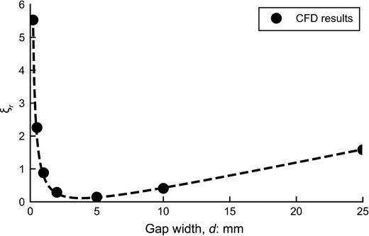
Dependency of the coefficient on the gap size for a hole diameter of 100 mm (results obtained with CFD analyses)
Dependency of the coefficient on the gap size for a hole diameter of 100 mm (results obtained with CFD analyses)
Equations 11 and 12 can be combined to express the total flow through all the drainage holes in the lining as a function of the differential pressure between the two sides of the lining ():
where is the water density, is the number of holes along the circumference, and is the hole spacing along the tunnel axis direction.
It is worth mentioning that, in principle, the gap size should be recalculated during the transient analysis, considering the displacement of the lining and rock mass, as it may change over time. However, this effect can be neglected if the variation in gap size remains limited during the transient. Consequently, a constant gap size can be used for the analysis in such cases.
When water exchanges between the gap and the rock mass are disregarded, Equation 9 simplifies to:
3.3 Fluid compressibility
The water in the gap is treated as a compressible fluid. Consequently, a change in the gap water pressure over the timestep results in a corresponding change in the gap volume according to the following equation:
where is the gap volume at time and is the water bulk modulus. The minus sign in Equation 15 reflects the expected behaviour: in the case of a decrease in the volume of the gap, the water pressure in the gap increases.
By combining Equations 3, 6, 7, 8, 14, and 15, the unknown water pressure in the gap at time can be determined:
Once the water pressure in the gap at time is known, the change of the tensile axial force in the lining at time can be calculated:
4. Model validation
Numerical fluid–structure interaction simulations were carried out to validate the proposed model using ANSYS Mechanical (ANSYS Inc., 2022).
The solid domain (Figure 4) represents the lining and a portion of the rock mass using elastic finite element method (FEM) elements with Young’s moduli of 35 GPa for the lining and 30 GPa for the rock mass. The geometry includes an excavation radius of 5.34 m and a lining thickness of 0.42 m, with a 1 mm gap separating the lining from the rock mass. The model extends 2 m in the out-of-plane direction, corresponding to the spacing of the drainage holes along the tunnel axis. To replicate the infinite medium boundary condition, elastic springs are applied at the extrados of the rock mass elements. Leveraging the symmetry of the system, which arises from the presence of nine drainage holes, the model is reduced to a 40° sector of the lining.
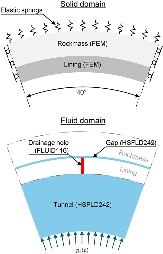
The fluid domain simulates the water inside the tunnel and within the gap using hydrostatic elements (HSFLD242). These elements can model compressible fluids by linking volumetric changes to pressure variations and assume a uniform pressure distribution within each element. The hydrostatic elements are coupled to the structural elements used for the lining and rock mass, enabling the transfer of pressure and displacement across the fluid–structure interface.
In addition, these elements can account for mass flows entering or exiting the fluid domain, resulting in corresponding pressure increases or decreases. Mass flows are simulated using a pipe element (FLUID116), which models the 100 mm dia. drainage holes in the lining connecting the tunnel to the gap. This element also incorporates head losses associated with water flow, as illustrated in Figure 3.
The pressure transient is modelled using an idealised sinusoidal variation of internal pressure with an amplitude of 2 MPa and a period of 20 s, as shown in Figure 5(a). Figure 5(b) presents the numerical model results in terms of axial force within the lining, showing how the axial force within the lining is influenced by the rate of internal pressure variation.
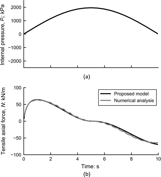
The same case is reproduced with the proposed analytical model adopting the following parameters: lining radius = 5.13 m, rock mass radius = 5.34 m, lining thickness = 0.42 m, Young’s modulus of the lining = 35 GPa, and Young’s modulus of the rock mass = 30 GPa. The lining is drained by incorporating = 9 holes positioned along the circumference, each having a diameter of = 100 mm and a spacing of = 2 m along the tunnel axis direction. To model the gap between the lining and the rock mass, a gap size of = 1 mm is adopted.
The results of the proposed model are shown in Figure 5(b) in terms of axial load in the lining, where a perfect match is observed between the numerical and analytical simulations, confirming the validity of the model in accurately predicting the lining behaviour under transient conditions.
5. Examples of application
5.1 Analysis of idealised transient events
The model described in the previous sections is applied to study some idealised transient events in order to highlight specific aspects of the response of a reinforced concrete lining during such events.
In these simulations, the water pressure in the tunnel is assumed to increase linearly by 1 MPa at three different rates: 2, 1, and 0.5 MPa/s, representing water pressure variations similar to water hammer scenarios. The dimensions of the lining and rock mass are set as follows: lining radius Rl = 5 m, rock mass radius = 5.25 m, and lining thickness = 0.5 m.
Two cases are considered: one in which the lining is drained only by longitudinal cracks, and another in which the lining is drained solely through radial holes. For the latter case, the configuration includes nine holes with a diameter of 100 mm and a spacing of 2 m along the tunnel axis direction.
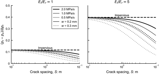
The results obtained by the model are presented in figures, showing the differential pressure () acting on the lining as a ratio of the internal pressure increase (). The dashed horizontal line indicates the outcome of an impervious lining behaviour during a transient, meaning that no water flows occur through the lining. It is important to note that even in the impervious case, part of the internal pressure variation is supported by the rock mass due to its stiffness. Approximately 10% of the internal pressure variation acts as a load on the lining when the rock mass modulus is equal to that of the lining. This percentage increases to approximately 40% when the rock mass modulus is five times lower than that of the lining.
The drainage capacity of the lining, allowing water to pass through, further reduces the loads acting on the lining. For a cracked lining (Figure 6), the reduction of the differential pressure increases with the crack width and the number of longitudinal cracks, while it decreases with the rate of variation of the internal pressure, as expected. With few cracks along the lining circumference (crack spacing in the order of 10 m), the lining behaviour is essentially impervious. As the crack spacing decreases and the number of cracks consequently increases, the impact of the cracks becomes more significant, reducing the load on the lining compared with the impervious case. When the lining is completely cracked (i.e. crack spacing on the order of decimetres), the load on the lining is approximately halved compared with the impervious case.
A lining drained with holes (Figure 7) is even more effective in reducing the loads during a transient. Even with a 1 mm gap around the lining, the loads are approximately halved compared with the impervious case. A gap in the order of a few millimetres reduces the loads on the lining by approximately three-quarters. This highlights the importance of proper drainage to alleviate the loads and stresses on the lining during transient events.
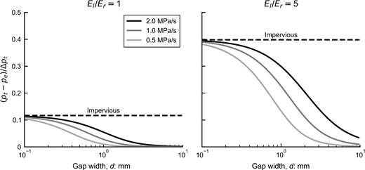
Differential pressure acting on a lining drained with holes during a transient event
Differential pressure acting on a lining drained with holes during a transient event
Based on the findings of this parametric analysis, it is crucial to account for flows through holes in a lining equipped with drains during transient events to avoid a significant overestimation of the loads on the lining. However, for a lining drained through cracks, its behaviour can be conservatively yet reasonably assumed impervious during transient events, except in the case of a fully cracked lining.
5.2 Analysis of a real transient event
Figure 8 presents the initial 20-s segment of a transient event in a real PSP. The figure illustrates the time history of the internal water pressure during this event, obtained through hydraulic analyses.
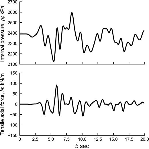
To analyse the response of the lining–rock mass system during this transient event, the proposed model is utilised. The simulation takes into account the following parameters: lining radius = 5.13 m, rock mass radius = 5.34 m, lining thickness = 0.42 m, Young’s modulus of the lining in tension = 10 GPa, Young’s modulus of the lining in compression = 20 GPa, and Young’s modulus of the rock mass = 9.3 GPa. The lining is drained by incorporating = 9 holes positioned along the circumference, each having a diameter of = 80 mm and a spacing of = 2 m along the tunnel axis direction. In addition, an initial gap size of = 2 mm is considered between the lining and the rock mass. The water flow through the rock mass is disregarded in this analysis because of its low permeability, which is of the order of 10−9 m/s.
The results of the simulation are presented in Figure 8, illustrating the time history of the axial force variation () within the lining during the transient event. The maximum tensile force in the lining reaches approximately 100 kN/m, while the maximum compressive force is about 50 kN/m.
It is crucial to emphasise that the axial force response of the lining does not directly follow the internal pressure, as it would in a case where the lining is impervious. In such an impervious case, the maximum and minimum forces within the lining would align with the maximum and minimum variations of the internal water pressure. However, in the case of a drained lining, the axial force within the lining is influenced by the rate at which the internal pressure changes.
When the internal pressure variation reaches its maximum rate, it results in the highest flow through the lining, consequently leading to the maximum differential pressure () acting on the lining, as demonstrated by Equation 10 or 13. Conversely, when the internal pressure is at its maximum or minimum, the rate of variation becomes zero, causing the flow through the lining, differential pressure, and eventually the axial force within the lining to be negligible. Both these behaviours are clearly observed in Figure 8.
This example demonstrates the versatility of the proposed mathematical model, allowing it to simulate the behaviour of the lining–gap–rock mass system under any variation of internal water pressure during a transient event. This capability facilitates the determination of the evolution of axial force within the lining, which is essential for evaluating stress variations within the lining. These stress variations are crucial inputs for conducting fatigue verifications.
6. Conclusions
This study fills a significant gap in the existing literature by introducing a dedicated model to evaluate the behaviour of hydraulic tunnel reinforced concrete linings during transient events. The model, developed due to the absence of relevant examples in the literature, aims to simulate the complex interplay of mechanical and hydraulic factors within the lining–rock mass system.
The application of the model allows for the evaluation of the variation in axial force within the lining during transient events, contributing to understand the potential fatigue issues arising from notable pressure transients and unsteady flow in hydropower plants. This addresses a growing need in practice due to the increasing prevalence of PSPs used for grid stabilisation, characterised by more frequent load changes and start/stop sequences of operations, compared with those for hydropower systems designed as base load plants.
To demonstrate the performance of the proposed model, practical examples are given for evaluating the behaviour of reinforced concrete linings during transient events. Based on the application of the proposed model, linings drained through cracks can be considered conservatively yet reasonably impervious during transient events, except in the case of a fully cracked lining. However, it is crucial to account for flow holes in a lining equipped with drains during transient events to avoid a significant overestimation of the loads on the lining.
Acknowledgements
The author would like to express his gratitude to Future Generation Joint Venture and Webuild SpA for providing the necessary resources throughout the development of this research. The intellectual property of the work presented in this paper belongs to Future Generation Joint Venture and Webuild SpA.
