
Several very large offshore windfarms are now planned for construction in hostile, remote locations in waters around the UK, where they present some significant new engineering challenges in bringing large quantities of electrical power back to shore. The design, construction and operation of large-scale power plant 100 km or more out to sea requires considerable design and construction skills. These windfarms require very robust electrical transmission systems with high availability and minimal maintenance requirements that meet strict national grid codes and also relieve stresses from the wind turbines by isolating electrical transients from the mainland grid. The systems must also be suitable to withstand the harsh conditions of the North Sea. This paper highlights how high voltage direct current (HVDC) systems utilising voltage-source converter (VSC) technology are set to play an important role in connecting offshore windfarms to the grid, and outlines the solutions that are now successfully being rolled out.
1. INTRODUCTION
With several very large offshore windfarms planned to be built off the coasts of Europe, many of which will be in the hostile, remote locations in waters around the UK, a number of engineering challenges must be overcome. The design, construction and operation of large-scale power plant 100 km or more out to sea requires significant design and construction skills. This paper highlights the challenges involved in developing high voltage direct current (HVDC) technology to meet this requirement, and outlines the solutions that are now successfully being rolled out.
According to the European Wind Energy Association (EWEA), European Union (EU) countries installed more wind energy capacity during 2008 than any other single electricity-generating technology.1 Some 36% of all new electricity-generating capacity installed in the EU during 2008 was wind-based – exceeding all other technologies including natural gas, oil, coal and hydro power.
A total investment of about €11 billion saw an average of 20 wind turbines installed for every working day of 2008 in Europe, bringing the EU’s total operational wind energy capacity to 65 000 MW – 15% higher than in 2007. In a normal wind year, this generating capacity will produce 142 terawatt hours (TWh) of electricity, equivalent to around 4.2% of the EU’s total electricity demand – and avoid the emission of 108 million tonnes of carbon dioxide per year (equivalent to taking more than 50 million cars off Europe’s roads).
While offshore’s proportion of the EU’s total installed wind energy capacity is currently small, at 2.3%, it offers significant potential – especially north-western Europe, which accounts for a substantial proportion of the total European wind resource. The UK itself has been identified as one of the world’s best markets for offshore wind energy, as a result of its favourable combination of wind resource and the extension of the relevant legislation, the Renewables Obligation. According to the British Wind Energy Association (BWEA), UK waters offer a theoretical generation potential of close to 1000 TWh per year, which is several times the country’s annual electricity consumption.2
In February 2009, the UK had a total of 206 operational windfarms, with an installed capacity of around 3300 MW, according to the BWEA.2 Of these, nine were offshore, with a total capacity just under 600 MW. Of the 37 windfarms currently under construction in the UK, which will total 1500 MW, eight are offshore and will have a total capacity of almost 800 MW.
As owner of the seabed, the UK Crown Estate has a central role in the delivery of offshore wind. Its recent announcement of Round 3 of offshore windfarm development builds on the 8 GW of offshore windfarm projects currently under development and to be delivered by Rounds 1 and 2 of offshore windfarm development.3 Round 3 outlines the potential for an additional 25 GW of offshore wind energy, involving some very large windfarms – 500 MW-plus – significant distances from the shore (see Figure 1).
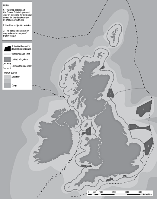
The UK’s Crown Estate Round 3 offshore wind proposals offer potentially 25 GW additional generating capacity, mainly through very large (500 MW-plus) offshore wind farms
The UK’s Crown Estate Round 3 offshore wind proposals offer potentially 25 GW additional generating capacity, mainly through very large (500 MW-plus) offshore wind farms
However, the construction of very large offshore windfarms presents some significant new engineering challenges in getting large quantities of electrical power back to shore. The design, construction and operation of large power plant – located far out at sea in hostile environments – require significant skills in design and construction.
The overall aim is to design a very robust electrical transmission system with high availability and minimal maintenance requirements that meets not only the strict national grid codes but also to relieve stresses from the wind turbines by isolating electrical transients from the mainland grid. Another important requirement is to design a system that can withstand the harsh and sometimes very hostile offshore climate of the North Sea.
2. ADAPTING HVDC TECHNOLOGY
For well over a century, HVAC has been seen as the natural choice for electrical power transmission. While HVDC has been commercially available since the mid-1950s, it has mainly been used for point-to-point, high-capacity bulk power transmission links over long distances or for the interconnection of asynchronous grids.4
Significant improvements have been made over the years in the performance of wind-conversion systems, which have enabled wind turbines to be connected to the transmission grid and be safeguarded against surges in power generation. HVDC is emerging as a robust and economically feasible alternative. An example is ABB’s patented ‘HVDC light’ voltage-source converter (VSC) technology, based on series-connected power transistors rather than thyristor valves. It offers superior reliability and stability for connecting sustainable energy schemes in harsh environments – including offshore wind power applications.5
What makes VSC-based HVDC transmission solutions attractive for connecting offshore wind farms to onshore electricity grids is their inherent voltage-controlling capability. The capacitance per unit length makes AC cables impractical for larger power transmission for distances above 50–70 km: a significant amount of reactive power is generated, and low-frequency resonances may result in instability. Moreover, traditional thyristor-based HVDC transmission systems are not so attractive, as a synchronous compensator or static synchronous compensator (STATCOM) may be required at the wind farm in order to maintain a smooth line voltage for the thyristors to commutate against. This is not an issue for VSC-based HVDC transmission systems that use pulse-width modulation (PWM) transistor VSCs to generate the fundamental voltage.6
3. RECTIFYING, INVERTING AND CONTROLLING
VSC-based HVDC uses series-connected power transistors that enable VSCs to be connected to networks at high voltages that were previously unattainable. Such solutions can be used for power transmission, reactive power compensation and harmonic/flicker compensation. With fast vector control, this converter solution enables independent control of active and reactive power while imposing low levels of harmonics, even in weak grids.
PWM is used for the generation of the fundamental voltage, with both the magnitude and phase of the voltage controlled freely – and almost instantaneously – within certain limits. This allows independent and very fast control of active and reactive power flows. In this way, a PWM-based VSC is close to an ideal component in the transmission network. From a system point of view, it acts as a zero-inertia motor or generator that can control active and reactive power almost instantaneously. Furthermore, it does not contribute to short-circuit power, as the AC current can be controlled.6
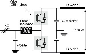
The most advanced converter designs are based on a two-level bridge, grounded by way of a midpoint capacitor (see Figure 2). This design philosophy ensures extremely low levels of induced ground currents, both in steady-state and dynamic operation. This feature is one of the critical factors for implementing an HVDC system in an offshore environment: there is no need for any cathode protection in conjunction with the installation.
VSC-based HVDC enables fully independent control of both the active and the reactive power flow within the operating range of the design. Normally each station controls its reactive power contribution (both inductive and capacitive) independently of the other station. The active power can continuously and almost instantaneously be controlled from full power export to full power import. However, the flow of active power in the DC cables must be balanced, which means that the active power entering the HVDC system must be equal to the active power leaving it. A difference in power would mean that the DC voltage in the system would rapidly increase or decrease, as the DC capacitance increases its voltage with increased charge (and vice versa). With a normal design, the stored energy is equivalent only to the power that would be transmitted by the system for around 2 ms.
To achieve this power balance, one of the stations has to control the DC voltage. This means that the other station can adjust arbitrarily the transmitted power within the power capability limits for the VSC-based HVDC system design, in which the station that controls the DC voltage will adjust its power to ensure that the balance (that is, constant DC voltage) is maintained. The balance is achieved without telecommunications between the stations: it simply requires the DC voltage to be measured.
In case of a voltage collapse, or black-out, a VSC-based HVDC converter can instantaneously switch over to its own internal voltage and frequency reference and disconnect itself from the grid. The converter can then operate as an idling ‘static’ generator, ready to be connected to a ‘black’ network.
4. OFFSHORE CONSTRAINTS
With the constraints placed on space and weight on offshore installations, VSC-based HVDC offers some important advantages.7 Since the filters are small, VSC-based HVDC can be made compact and lightweight compared with other solutions. Apart from the obvious need to make the converter station small and light, the harsh offshore environment and the remote location places a number of other demands on the converter station and equipment
safety is paramount
salt and humidity place severe requirements on the choice of materials and surface treatment
maintenance needs must be minimised
extensive monitoring is needed.
Apart from the main transformers, all high-voltage equipment needs be installed inside compact modules on the offshore platform. The ventilation system in the modules must protect the high-voltage equipment and the electronics from salt-laden and humid air. The main circuit equipment is therefore exposed to lower environmental requirements than a normal outdoor installation, which enables a more compact design. The ventilation must also take airborne losses into consideration. An advantage of being offshore in the North Sea, of course, is that cold (5–11°C) water for cooling is readily available.
VSC-based HVDC converter stations can be fully automated or remotely operated. The goal is to maintain very high performance of the link throughout the whole operational lifetime. The annual maximum energy unavailability owing to scheduled maintenance must be measured in days, rather than weeks.
The control system and its auxiliary systems should have an inherent extensive internal monitoring system built in, so that the status of the system can be continuously monitored from a remote location.
In offshore windfarm applications, VSC-based HVDC solutions use extruded polymer cables, which are a strong, flexible and cost-effective alternative for severe conditions and deep waters – see Figure 3. This cable type has a copper or aluminium conductor surrounded by a polymeric insulating material, which is very strong and robust. The water sealing of the cable has a seamless layer of extruded lead and finally two layers of armouring steel wire in counter helix to provide the mechanical properties.
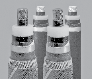
Typical VSC-based HVDC cables – submarine versions at the front, land cables at the rear
Typical VSC-based HVDC cables – submarine versions at the front, land cables at the rear
To see how these cables compare with conventional AC cables, consider the requirements for a 550 MW subsea connection over a distance of 75 km.5 For an AC scheme, a three-core 220 kV cross-linked polyethylene (XLPE) cable would be required with a copper conductor cross-section of 1600 mm2 and copper wire tensile armour. The weight of the three-core cable is 3 × 60 kg/m = 180 kg/m. However, a VSC-based HVDC link would require only two 150 kV cables with a copper conductor cross-section of 1400 mm2 and steel wire tensile armour. The weight of the two cables is 2 × 32 kg/m = 64 kg/m, that is around one third of the AC scheme.
5. MEETING STRICT GRID CODES
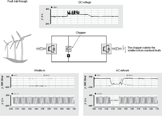
As the proportion of wind power generation increases, grid codes requirements are becoming stricter. Most grid codes today set requirements on the so-called ‘fault ride-through’ or ‘low-voltage ride-through’. Typically, wind turbines or farms must be able to survive sudden voltage dips typically down to 15% of the nominal grid voltage for up to 140 ms.
In a ‘standard’ VSC-based HVDC transmission link between two utility grids, similar scenarios are solved by instantaneously reducing the input power of the rectifying VSC through closed-loop current control. In a strong grid with much greater power generation capacity than the rated transmission capability, this will occur without a significant change in the voltage. Windfarms are different, however. The windfarm network is much smaller than a typical utility grid and, as a consequence, weaker. Also, its rated generation normally matches the rated HVDC transmission capability. A fast reduction in the input power of the rectifying VSC may therefore lead to a significant increase in the wind farm bus voltage – resulting in an over-voltage tripping of the VSC and/or the wind turbines.
The solution used is very robust, and leaves the windfarm unaffected during main grid faults. The DC chopper is a high-energy resistor in the DC circuit that evacuates the surplus of energy during network faults when power transmission is not possible (see Figure 4). This means there will be no abrupt change in the output power from the wind turbines and the disturbance seen by the wind turbines will be minimised. One positive side-effect of having an HVDC link with a DC chopper is that the windfarm becomes ‘immune’ against electrical transients and the possible resulting mechanical stresses on equipment in the nacelle, such as gearboxes.
6. BLACK-STARTING OF ISLANDED OFFSHORE NETWORKS
The ability of VSC-based HVDC converters to generate a voltage whose amplitude and phase can be controlled as desired enables offshore networks to be energised very quickly during a black start.6 This is especially useful when it comes to starting an offshore network. The converter transformer will be equipped with a special auxiliary power winding for self-supply of the converter station, and the control system will have special schemes for a black start.
7. BASIC PRINCIPLES ARE ALREADY ESTABLISHED
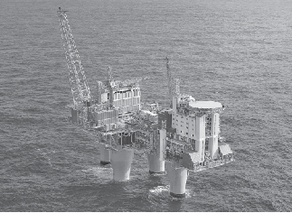
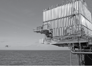
The design, construction and operation of large-scale power plant, located far out at sea in harsh environments, requires significant skills and experience. Transporting the power to where it is needed demands innovation and the most up-to-date technology. The basic principles have, however, already been well established in the Troll-A and Valhall power from shore projects, in which VSC-based HVDC is used to provide power for offshore oil and gas platforms,8,9 see Figures 5 and 6.
8. CONCLUSIONS
Reliable and robust VSC-based HVDC will help enable the roll-out of several gigawatts of offshore wind generation in Europe. The valuable lessons learned by the engineers working on VSC-based HVDC will help to reduce the technical – and ultimately financial – risks faced by offshore windfarm developers when it comes to choosing a suitable and reliable transmission system.
