
Rock anchorage failures occurring only 6 years after installation to support a major cutting on the A5 trunk road west of Corwen in North Wales were exhaustively investigated, ultimately resulting in their removal and partial replacement. The failures in Glyn Bends rock cutting were detected when head assembly components were found on the ground during a routine inspection. The investigation of the 120-year design life double-corrosion-protected anchorages included the innovative use of endoscopy, selectively supported by subsequent physical dismantling and metallurgical examination. On the basis of the investigation and the subsequent recovery of some of the installed anchorages, it was confirmed that at least 24% of the anchorages originally installed had their factory corrosion protection fatally compromised by partial removal. This was aggravated by the omission of the caps, which allowed the protective grease to escape, and placing many anchorages in recesses which aggravated surface corrosion. Metallurgical investigation emphasised that corrosion protection is critical to very-high-yield steels. No records of the alterations made were ever produced. The trunk road had to be closed at short notice for 8 months on public safety grounds while the main cutting face was reprofiled to a safe unsupported angle on the north side and re-anchored on the south side.
1 Introduction and background
1.1 Background to cutting scheme and local geology
Comprehensive background details to the 1990s highway scheme and the local geology are provided by Hooper and Rowlands (1996), Green (1999), Nichol (2002), Green and Hawkins (2005) and Wilson and Kemp (2009).
Briefly, the A5 London-to-Holyhead trunk road was improved through North Wales by Thomas Telford to reduce the travel distance for stagecoaches. Modern traffic requires route improvements, one such being the Glyn Bends rock cutting, 8 km west of Corwen at an elevation of 260 m above ordnance datum. It was formed to bypass the Afon Ceirw gorge, where the old road was narrow and twisty between uphill rock faces and downhill retaining walls.
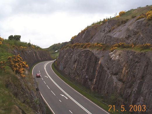
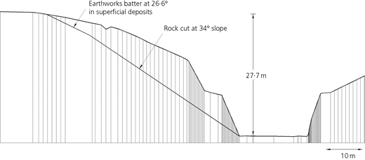
The design was required to be sensitive to the upland location and proximity to the Snowdonia National Park. A steep-sided, presplit blasted cutting reduced visual impact but required substantial support by way of rock anchorages (Figure 1). Cutting dimensions are 640 m long by up to 31 m deep, with slopes of up to 70°.
The cutting exposes calcareous volcanoclastic sandstones, siltstones, tuffites and lithic tuffs of the Ordovician Gelli-grin Formation, metamorphosed by the Caledonian orogeny. The sequence of dark bluish-grey metasiltstone and metamudstone beds includes 23 metabentonite beds, which as the weakest beds present have been sheared by mass deformation over geological time. The rock generally has unconfined compressive strengths of between 50 and 100 mPa.
The metabentonite beds represent a series of altered volcanic ashes (tuffs), typically 0·1 to 1 m thick. The principal clay mineral present is illite, a non-swelling clay mineral; the original primary mineral would have been smectite prior to metamorphism.
The sequence generally dips southwards at 30° to 65°, an unfavourable orientation resulting in potential planar failures in the cutting north face, complicated by local folding and faulting. An angle of friction φ ′ of 47° on discontinuities in the metasiltstones is reported, reducing significantly to 14° in the metabentonites. Residual shear strength values for bentonitic material of between 8° and 15° have been recorded.
1.2 Original cutting support
In order to achieve the 70° faces desired, presplit blasting techniques were employed, with the provision of half-height benches and isolated vegetated ledges to improve visual amenity. Maximum lift height was 6 m, subsequent excavation following this in stages as support was installed where required.
One planar slip occurred during construction in the upper face. Part of the lower north face had potentially serious temporary stability issues owing to the orientation of low-strength beds. Large ‘dowels’ comprising grouted steel tubes set in 300 mm dia. vertical drillholes were installed in advance of the excavation of a 150 m long section of this face. Drain holes were drilled 15 m into the rock mass.
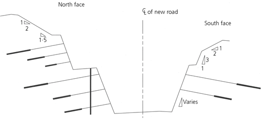
A total of 330 rock anchorages were installed at regular horizontal and vertical intervals where the northern cutting slope was vulnerable to large-volume planar and wedge-type failures (Figure 2). Seventy were required in the 11 m high southern face.
A total of 400 double-corrosion-protected bar anchorages were installed, 330 in the north and 70 in the south face. On grounds of the visual environment, many anchorage heads were recessed into the face by way of pockets excavated following bulk excavation. Standard head caps were omitted for the same reason. Three anchorage types were employed as follows
RA1 – total length 5–10 m, free length 3 m, working load 400 kN, diameter 32 mm, steel grade 900/1030 N/mm2
RA2 – total length 10–15 m, free length 5 m, working load 600 kN, diameter 36 mm, steel grade 1080/1230 N/mm2
RA3 – total length 15–20 m, free length 8 m, working load 600 kN, diameter 36 mm, steel grade 1080/1230 N/mm2.
Face plates were 300 mm2 by 50 mm thick with a 300 mm long back-plate tube (‘trumpet’) to ensure continuity of corrosion protection with the tendon. All were grouted into boreholes drilled downwards at 10° to 15° and seated on high-strength mortar pads.
2 Anchorage failures
2.1 Initial failures
Routine inspections in 1999 found the anchorages to be defect free, but in 2002 the following defects were reported.
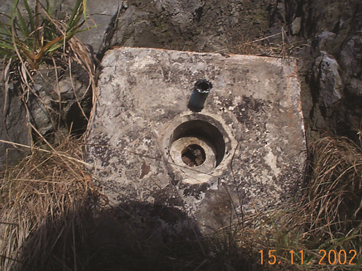
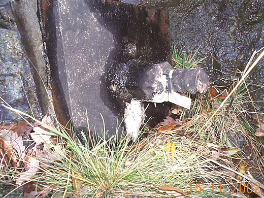
Anchorage RA2-52 head assembly including faceplate had fallen to the floor owing to shearing of the tendon immediately behind (Figure 3).
Anchorage RA2-126 nut with a sheared-off section of tendon had fallen onto the recess ledge.
(All) ‘Rock bolts and plates very rusty’ – this comment believed to refer to the anchorages.
Both failed anchorages were inspected yielding the following details.
RA2-52. The fractured tendon with nut and the faceplate was on the ground. Probing of the grease ports found them to be dry, with the remote end blocked by cement grout. The grease void was virtually full of fractured cement grout, with only a trace of grease, and the back-plate tube was only 60 mm long. There was no sign of the tendon protective sheathing or seal in the collaring zone.
RA2-126. The fractured tendon and nut were in the grassed recess, which was wet. The grease points and the back-plate void were devoid of grease or grout. Removal of the faceplate revealed that the back-plate tube had been reduced from 300 to 60 mm. The tendon rubber seal was visible but partly missing and had been seated very close to the back of the faceplate. Factory grout inside the seal was shattered.
It appeared that the defects observed must have been obvious to the installers. It was also clear that any attempt to check lift these anchorages would have caused further damage.
A desk study did not reveal any comparable failures since the advent of BS 8081 (BSI, 1989) nor were any project records relating to relevant construction problems forthcoming. This was followed by an incremental series of investigations, described in the following sections, which developed as they established that other anchorages might be at risk.
2.2 Failures during investigation
Three further tendons broke while being load tested, and one failed by excessive extension.
RA2-37. At a little over its 600 kN working load, the tendon failed approximately 290 mm behind the front of the faceplate. The head assembly was broken out to reveal back-plate conditions. On faceplate removal, it was found that the tube had been shortened to 95 mm, although it still contained some grease. The tendon rubber seal was intact, but located remote from the shortened tube, and the tendon was severely eccentric to the faceplate. The tendon was surface corroded behind the faceplate despite invasion of grout. Void sealing was clearly ineffective, and proper application of load was deemed improbable.
RA2-147. At 320 kN loading, the tendon failed 134 mm behind the front of the faceplate. Minor water seepage through the grease void was evident. The head assembly was broken out to allow investigation of back-plate conditions. It was found that the tube had been shortened to a length of 120 mm, but still contained some grease. The tendon rubber seal was absent, as was any secondary grout, the latter probably owing to the grout port being blocked by faceplate pad mortar. The failed tendon stub was sent for metallurgical investigation of the failure cause. A sample of grease was also sent for analysis of type.
RA3-7. On reaching a load of 896 kN, this 36 mm tendon failed 216 mm behind the front of the anchorage faceplate. Following the failure, the head assembly was broken out to allow full investigation of back-plate conditions. It was found that the tube had been shortened to a length of 100 mm. Fragments of grease and secondary grout were found within the tube. The rubber seal was intact on the tendon, but it was located down hole from the end of the shortened faceplate tube – in other words, no effective seal existed to the grease void. The failed tendon stub was sent for metallurgical investigation of the likely cause of the failure.
RA3-105. Severe extension occurred under load, indicating that the tendon fixed length had effectively decoupled from the rock. Nine anchorages exhibiting very low residual load were restressed and rechecked 12 months later; of these, one exhibited severe repeated loss of load.
3 Laboratory metallurgical and corrosivity investigations
3.1 Metallurgical investigations
The tendon stubs representing the two initial failures were sent for metallurgical analysis by Doosan Babcock, as were two of the subsequent failed stubs.
The investigation activities for the initial failures comprised tensile testing of machined specimens, chemical analysis, fractographic examination by microscope of the failed surfaces and metallographic examination of microstructural features. The findings may be summarised as follows.
The tendon material complied with the required specification.
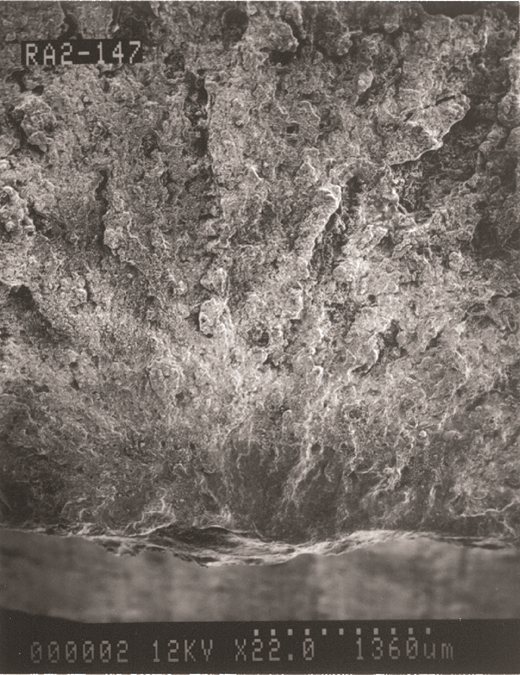
A complex progressive corrosion failure mechanism, probably of intermittent nature, was evidenced as being potentially associated with fatigue in corrosion pits, developing through ‘thumbnail’ features into hydrogen-assisted cracking, as illustrated in Figure 4, which was also driven by overstress as the effective tendon section reduced.
Intermittent corrosion pit/crack growth could be related to either the wet/dry cycle present in the rock face, or to diurnal/seasonal movements in the surface of the rock mass owing to external temperature and/or direct sunlight.
Fatigue enabled by the decoupled nature of the anchorage free length was a contributory driver of failure but not an initial causal factor.
Final failure would have occurred as a low-energy event owing to stress dissipation during crack propagation.
Failure in the corrosion protection system was the indicated cause of tendon failure, with high-tensile steel being particularly prone to hydrogen embrittlement.
Since stress was not indicated as an initial failure driver, accidental overstressing during acceptance test work probably did not initiate the failures.
Anchorage RA2-147 microscope view of failure initiation location (Doosan Babcock)
Anchorage RA2-147 microscope view of failure initiation location (Doosan Babcock)
The subsequent failure analyses were carried out along similar lines to the initial exercise, except that the fracture surfaces were relatively ‘clean’, having been protected since the occurrence of failure, so the fractographic and metallographic examinations were clearer, resulting in improved confidence in the findings. In addition, ultra-slow strain rate (SSR) tensile testing was carried out in air and in groundwater collected on site to determine susceptibility to environmentally assisted cracking mechanisms.
The mechanical results of the SSR tests were examined as well as the post-test fracture surface characteristics, which were compared with the fracture surfaces of the actual failed tendons. The SSR fracture surfaces developed in groundwater were most analogous to the actual failure surfaces, as might be expected. Other findings repeated those from the initial tests.
In addition to physical loss of grease by displacement or thermal mobility, exposing the tendons to corrosion, it was noted that grease would become emulsified after coming into contact with grout or groundwater of an alkaline nature, that is to say it would be degraded by intermixing.
Expert review and analysis indicated that around 50% of anchorages suffering from compromised corrosion protection would fail over a 50-year period. The overarching lesson was the criticality of corrosion protection integrity when installing high-yield anchorages. Notably, none of the lower-grade anchorages failed.
3.2 Corrosivity investigation
Groundwater samples from the anchored rock face were recovered in summer and winter conditions, in order to establish whether tendon failures could be in part attributed to aggressive site conditions. Samples were analysed for pH levels of selected chemical species. From the parameters obtained, an approximate value of the Langelier Index for the groundwater was calculated. The Langelier value obtained was −1·0 to −1·5, indicating that the groundwater may be mildly corrosive.
Redox potentials for the summer groundwater samples were measured, and SIG sulfide tests were conducted. The results from these tests indicated that the works were not susceptible to attack from sulfate-reducing bacteria. In the context of double-corrosion-protected anchorages, these findings were considered favourable to anchorage longevity.
The grease used to protect high-yield steel must be of the specification provided by the manufacturer. When anchorage RA2-147 failed, the faceplate tube contained a remnant of grease. A sample of this grease was sent for analysis in order to determine whether it was of the correct type. The results were not conclusive because amounts of water and ferrous corrosion products contained in the grease were too high.
4 Field investigations
4.1 Non-intrusive investigations
4.1.1 Visual inspections
Detailed visual inspection of all anchorage heads was achieved using roped-access techniques where necessary. Specific observations and deductions may be summarised as follows.
Paintwork condition of tendon ends and nuts was poor for about 25% of anchorages.
Around 45% of tendon stubs had been shortened after installation to the extent that check lifting and restressing were not possible.
Paintwork condition of faceplates was very mixed, with local to general onset of corrosion attack in many locations, especially in areas of wet face.
Grass in the horizontally cut base of some recesses was aggravating corrosion.
Several 32 mm and 36 mm tendons and faceplates had been mismatched.
Around half of faceplate grease ports were dry or earthy, 10% were damp, 15% appeared to be filled with grout and 5% were encrusted with lime, with clean or rusty water flowing from a few.
Weepage of grease from tendon/nut/faceplate contacts was occasionally found.
At around 4% of anchorages, mostly at height, secondary grout ports were empty.
Around 3% of mortar pads under the faceplates were of very poor construction.
The overall visual impression was of anchorages vulnerable to both external and ‘internal’ corrosion attack, by way of observed and implied deficiencies (see Figure 5). The grease void at the head of tendon factory sheathing often appeared devoid of grease, sometimes being grouted up or even flowing with water. Specific physical defects were the mismatched faceplates, missing secondary grout and shortened tendon stubs. Taken together with the shortened back-plate tubes of the failed anchorages, there was serious concern about the likely long-term competence of the support system, with clear implications of more shortened back-plate tubes.
4.1.2 Load check lifting
Anchorages in the vicinity of the failed anchorages were first subject to check lifting tests, where possible. The results obtained initially indicated that a substantial number of anchorages were carrying loads well in excess of design working load. (As investigations progressed, a better understanding of back-head conditions allowed the conclusion that many of these simply could not be lifted owing to physical obstruction.)
The exercise was extended until all anchorages capable of being lifted had been checked. Roped-access techniques were used for the first phase, employing a one-piece closed stool and jack. For safety reasons, and to gain better information on nut/plate behaviour, this changed to mobile elevating work platform access employing a separate open stool.
Lift-off load was determined by graphically plotted load–extension data, supported by feeler gauge observations. There were frequent instances of the nut coming free at higher load than when the feeler was first inserted, reflecting in imprecise graphical plots, indicating a lack of tendon to faceplate concentricity.
As results were compiled, a 29% incidence of service loads more than 10% in excess of nominal working loads caused more concern. A small number of instances of very low load were also found. One hundred eighty-two anchorages with shortened tendon stubs were not available for lifting, thus extending concerns.
A further element of concern was added when interpretation of free length from extension data identified around 30 anchorages where the indicated free length was significantly different to that identified in the maintenance manual.
4.1.3 Recovery of anchorage head assemblies
During the remedial works to the cutting, as discussed later, the north face was reprofiled without any attempt to protect the original tendons, but much steel in the spoil was recovered. Many head assemblies were recovered in a variable state, some with the tendon and nut still homed. The 70 heads in the south face were dismantled and saved.
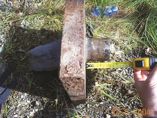
A total of 240 anchorage heads were ultimately stored and examined, a substantial 60% of the original stock. Of these, 78% had been modified by cutting short the back-plate tube. Twenty-six per cent of the tubes had been cut to 75 mm long or less, rendering homing of the tendon seal impossible and inevitably compromising grease void integrity (see Figure 6).
Examination further revealed that at least 15% of tendon seals had been totally removed, rendering grease void sealing impossible. Many of these known instances were from the south face, as the north face tendons were often damaged by blasting and muck shifting.
In total, 96 anchorages (40%) of all those examined were shown to be incapable of proper corrosion protection. This represents 24% of the total originally installed.
4.2 Intrusive investigations
4.2.1 Endoscopy
Because many tendon stubs were too short to enable physical dismantling, an efficient technique to assess the concealed parts of head assemblies was required. A suite of representative anchorages was selected for endoscopic inspection, some subsequently physically dismantled to verify the endoscopy findings.
A high-specification Olympus IPLEX industrial endoscope was hired for 1 week. This instrument comprises a 6 mm dia. flexible optical tip on a 3 m cable, with high-definition digital video camera and high-intensity light source. The optical tip is articulated to allow remote-controlled manoeuvring. Real-time images are displayed on a liquid crystal display unit and digitally stored in the base unit memory. To assess the condition of the anchorages, the endoscope tip was inserted into the 8 mm dia. grease ports which penetrate the faceplate; this was made feasible by the lack of grease. Once through the faceplate, the tip was articulated and inserted deep into the grease void, allowing inspection of the concealed components.
The images recorded by the endoscope revealed cavities, voids and important features about the condition of the anchorage components and especially the presence of corrosion.
An example of an image obtained by endoscopy is shown in Figure 7. It illustrates the view looking down the anchorage from immediately behind the faceplate. The tube seen lying at the top of the borehole is the secondary grout tube, which should not be visible. This contrasts with correct anchorage head details, where the 300 mm faceplate tube sits firmly over the rubber seal, preventing grout from entering the grease void. The presence of the secondary grout tube in Figure 7 demonstrates that the tendon seal was not homed; additionally, the curved edge of the faceplate tube is missing, and secondary grout has clearly flowed into the void. In this example, it was concluded that the faceplate tube had been cut short during construction, preventing effective sealing and leaving the tendon exposed to moisture and air, in turn giving rise to corrosion within the zone, as exemplified by the anchorage failures.
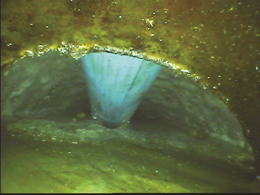
Subsequent breaking out of this anchorage confirmed that its faceplate tube had been cut short, and the conclusions of the endoscope investigation were proven, confirming that the condition of anchorages of this type can be assessed without the need to dismantle the entire head assemblage, provided that the grease void is empty.
Fuller details of the endoscopy work are provided by Nichol et al. (2015).
4.2.2 Physical dismantling
To confirm the results of endoscopy and obtain an improved understanding of physical issues with the anchorages, 13 locations were dismantled. Ten of these were conventionally dismantled and reassembled, but three required controlled demolition as the nut would not disengage.
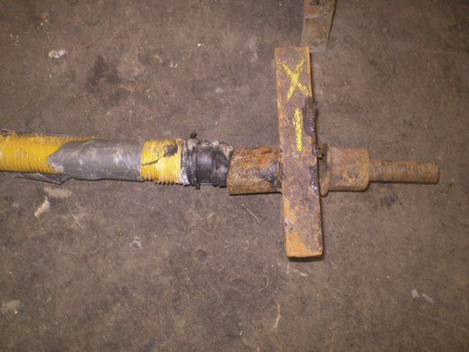
The ten represented all three anchorage types, differing locations and visual condition, including ‘good’ examples. Four tendons were proven to be eccentric, and seven back-plate tubes had been shortened to between 75 and 162 mm (see Figure 8). Only one grease void contained substantial grease; grout had invaded three. In one instance, the tendon seal was missing, in five others it was damaged. In two cases, the factory-applied tendon corrosion protection below the seal was damaged or partially removed.
These ten were revisited 12 months after reassembly in order to check for grease weepage from the faceplate ports. Substantial grease mobility was clearly evidenced.
The three anchorages that were demolished were in locations selected with regard to cutting stability consequences. Two were dismantled without incident and demonstrated similar installation defects as already reported. In both, the tendon rubber seal was totally missing and the back-plate tube had been cut short. The third, which collapsed explosively, was unusual in that all components were intact and homed, but in a severely eccentric manner, and with minimal grease in the twisted tube.
5 Summary of anchorage issues
The anchorage failures were caused by progressive intermittent corrosion associated with fatigue and/or hydrogen cracking leading to fracturing immediately behind the head assembly.
Final tendon failure occurred gently, not explosively, the detached tendon stub falling in situ owing to stress dissipation prior to detachment.
Accidental overstress during installation would not appear to have been a contributory factor to the failures, nor would any defect in the tendons as manufactured.
Such failures are rare, but high-yield anchorages depend critically on effective protection against corrosion, especially around the head assembly. The contract required double corrosion protection and a 120-year design life. Because caps (top hats) to these anchorages were omitted by design for visual amenity reasons, the general reduction in back-plate tube length and sometimes removal of the tendon rubber seal combined to enable the loss of corrosion protection in a critical location. Where secondary grout had occupied the grease void, this grout was vulnerable to cracking and did not provide substantive protection.
Grease in the back-plate void had been displaced in some instances by secondary cement grout and elsewhere by the passage of groundwater. More generally, grease loss was occurring through uncapped faceplate ports owing to thermal mobility. All installations were thus at risk of corrosion attack.
The situation was complicated by the installation for visual amenity of many anchorage heads in rock face recesses, the flat bases of which became vegetated, leading to loss of head assembly paint. The bitumastic paint specification failed to protect the exposed elements sufficiently, resulting in accelerated corrosion attack and a need for frequent maintenance.
The occasional mismatching of 32 mm and 36 mm anchorage components is inexplicable and appears to reflect poor practice. Secondary grouting also appeared to have been locally overlooked.
The late-stage reduction in tendon stub lengths for visual amenity reasons was unwise and prevented normal maintenance, in that the practice prevented check lifting and restressing at almost half of anchorages.
Endoscope work and the physical dismantling of a representative selection of anchorages indicated that the majority of anchorages were defective as already described. In only one instance was a full-length back-plate tube proved; reduction in length from 300 mm to between 60 and 180 mm appeared to have been the norm.
As a physical consequence of lack of homing of the seal to the tube, concentricity of the tendon to the faceplate would have been difficult to achieve. One-third of the anchorages dismantled were visibly eccentric, with implicit stressing issues. Elsewhere, if the seal was within a shortened tube it would be proximal to the rear of the faceplate and at risk of snagging during initial stressing and check lifting.
Physical snagging caused by these issues resulted in difficulties in undertaking and interpreting check lifting. Many graphical plots were of ragged appearance.
Local concerns were presented by a small number of tendons of reduced effective free length, plus at least one failure by pull-out during check lifting.
6 Actions arising from issues encountered
6.1 Road closure
As there was a significant risk of further anchorage failures, stability and semiquantitative risk analyses were carried out. These indicated that there was excessive risk to the road users, and the cutting was closed in May 2006.
6.2 Remedial works
6.2.1 North face
For the north face of the cutting, the option selected for the remedial works was to regrade the cutting to a stable angle at 34° from the horizontal (see Figure 9). The basis of this decision was dictated by the fact that the existing anchors could not be relied on even temporarily during any alternative option that included re-anchoring the slope, partially or in full.
6.2.2 South face
The rock structure was more favourable on the south side, as the bedding planes dipped into the slope. Five wedge failure mechanisms were the main area of instability of the cutting, formed by the intersection of a low-shear-strength bedding plane and a rock joint. Slope stability analyses were carried out at each unstable wedge location, confirming that anchorages were to provide long-term stability.
Four preliminary trial anchors were installed to confirm the design parameters using 40 mm and 50 mm grade 500/600 GEWI steel bars with fixed lengths of 1 and 3 m, with the shorter length being chosen to induce bond failure in the proving tests. Proving test loads up to 882 and 604 kN (80% of the characteristic strength of the steel bar) were applied to the 50 and 40 mm dia. bars respectively. The results for the 50 mm bar indicated a working bond stress in excess of 1·87 MPa without bond failure. However, the results of the test on the 40 mm bar showed the start of bond failure at 1·54 MPa. Furthermore, based on the results of the preliminary tests on the 3 m fixed length and using a nominal Young’s modulus for the steel (E) of 205 GPa, with an expected variation of ±5%, the apparent free lengths were found to exceed the criteria set out in BS EN 1537 (BSI, 2000). Confirmatory testing had to be carried out on samples of similar bars, which indicated E values of 198 GPa for the 40 mm bar and 200 GPa for the 50 mm bars. Using these values, which were lower than the nominal value given by the manufacturer, the apparent free length of all four trial anchors then complied with BS EN 1537.
On the bases of the preliminary test results, a fixed length of 4 m was chosen for the design. Working loads of 350 and 550 kN for the 40 and 50 mm dia. monobars, respectively, provided stability for the unstable wedges. A total of 27 anchorages were deemed necessary, compared with the original 70.
6.2.3 Construction
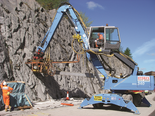
The remedial works on the north face were carried out by a combination of blasting and mechanical excavation. A total of 100 000 m3 of rock was removed and reused elsewhere.
The work on the south face included re-anchoraging of the rock slope, the installation of stainless steel dowels to support rock overhangs and the installation of netting and scaling of the rock face. Anchorages installed (see Figure 10) have double corrosion protection to BS 8081:1989 (BSI, 1989) with a design life of 120 years. The free lengths are 8 to 15 m, and the fixed length was 4 m. All 27 anchorages were subject to an acceptance test and then locked off at 110% of service load. These are being monitored on a regular basis as part of the maintenance manual for the scheme.
The road was reopened to traffic in July 2007, successfully delivered on time and budget (£6·5 million).
Fuller details of the remedial works are provided by Graham et al. (2015a, 2015b).
7 Conclusions
The cutting slopes at Glyn Bends were originally designed at 70° with rock anchorage support. The discovery of failed head assembly components during a routine inspection 6 years after installation triggered an exhaustive investigation, which concluded that many of the anchorages were at risk due to corrosion because of installation details.
The investigations undertaken included visual examination of all anchorages, check lifting of those anchorages that could be tested, dismantling of anchorages that failed during check lifting and selected others, metallurgical examination, inspection by endoscope and integrity testing. Of these, dismantling of anchorages, endoscopy and metallurgical examination provided the most significant contribution to the investigation.
The value of high-quality endoscopic images in gaining an understanding of the condition of concealed components of anchorages for asset management purposes was demonstrated at this site, although only because the grease compound was missing from most of the anchorages. As far as can be determined, this is the first reported case history on the application of this technique to anchorages.
Metallurgical laboratory work confirmed that very-high-yield steel anchorages are vulnerable to failure from fatigue arising from hydrogen embrittlement if the corrosion protection is compromised.
The investigations concluded that the failures occurred due to corrosion of the tendons, enabled by shortening of the tube (trumpet) behind the faceplate, which led to insufficient corrosion protection. In some instances, this situation was worsened by the removal of all or part of the factory-installed rubber seal from the tendon. This was further aggravated by the design omission of the caps, which allowed the grease to escape through the open ports, and the placing of many anchorages in recesses in the rock face, which aggravated surface corrosion. The situation was further worsened by the cropping of many tendon stubs, resulting in an inability to check lift or restress them.
No records were ever produced of any instructions relating to the alterations to the anchorage head assembly that fatally compromised the double corrosion protection system.
The recovery of a large number of the original anchorages following the blasting of the north face and the controlled dismantling and recovery of the south face anchorages confirmed that at least 24% of the total number of anchorages originally installed were incapable of acceptable corrosion protection performance.
Following road closure on public safety grounds, the cutting was reengineered by regrading the north face to a safe angle that did not require anchorage support, and re-anchoraging of the south face. The solution adopted was the one with the lowest level of risk, in terms of cost and programme and safety issues. The remedial works were undertaken successfully between November 2006 and June 2007. The road was reopened to traffic in July 2007.


Acknowledgements
The permission of Doosan Babcock Limited to use Figure 4 is acknowledged with thanks.
