An essay on the foremost British government soil mechanics laboratory from earliest times to 1957.
4. PART 4: 1948–1957
4.1. Second international conference
BRS has played a major role in the promotion of soil mechanics. From the Soil Mechanics Discussion Group that held meetings at the Institution of Civil Engineers during 1940–41, through the Committee for Soil Mechanics and Foundations (1946), to the British National Committee, set up to collect Papers for the Rotterdam Conference, the names of Cooling, Skempton, Golder and Glossop have been prominent.
The British National Committee submitted 72 papers, almost 20% of all the Conference papers, and 74 British delegates attended the Conference in Rotterdam during 21–26 June 1948: very different from Cooling as our only representative at the Harvard Conference. The Soils Section at BRS contributed 10 of these papers: 15 if the papers by Golder and Skempton, who had recently left the Section, were to be included. The Proceedings of the Conference formed a valuable stimulus and source of information for the research work at BRS.
4.2 Postwar embankment dams
4.2.1. Thorpe March
As part of the improvement of the River Don downstream from Doncaster, a 5·5 m high flood bank had been built from borrowed brown clay fill (cu = 29 kN/m2) to be along the south side of a new cut for the river. When the channel alongside was excavated, the flood bank failed, pushing the natural ground into the channel. Our investigation with the faithful ‘coffin’ equipment revealed soft blue clay (cu = 13 kN/m2) containing a layer of peat in the natural ground, passing under the bank, but cut by the side of the channel. A total stress analysis gave F = 1·6. We suggested that pore pressures in the peat under the weight of the flood bank could have spread under the lightly loaded toe and ground beyond, reducing the shear strength sufficiently to allow failure when lateral support was removed by channel excavation. To check this we installed 12 simple single-tube hydraulic piezometers, early in 1949, in the peat across a section of the flood bank to be built on the north side of the channel. The piezometers used discs of porous refractory brick as intake filters and 4·8 mm diameter soft copper connecting tubes. Each was placed in a small pocket of sand at the bottom of an augered hole in the peat layer, carefully sealed in with backfill. They were completely filled with air-free water initially, but gas from the peat got into them, and the tubes were refilled from time to time by passing more water through them to be expelled into the peat. This caused a temporary rise of pressure, but it soon dissipated to what was assumed to be a true value. As the flood bank was built, the pore pressures rose in the peat to a maximum value of ru = 0·7 under the centre of the bank, with some rise under the unloaded ground between the toe and the excavated channel. Because the channel had already been excavated, there was a free exit from the exposed peat, and the pore pressure did not rise as much as it probably did when the opposite bank had been built prior to channel excavation, and the new bank remained stable. This work was described by Ward et al.1
4.2.2. Usk and Daer
The next two large embankment dams to be built in Britain, the Daer in Scotland and Usk in Wales, were both designed by Binnie, Deacon and Gourley, who invited BRS to cooperate in a research study of the pore pressures developed in the fill of the 39 m high Daer. The BRS group agreed to cooperate in this research, and I was given the task of making and installing suitable piezometers. Following the design of the apparatus used by the US Bureau of Reclamation for their Anderson Ranch dam, which used intake filters of 3·8 cm2 area, I developed a better two-tube apparatus with larger intake filters of 20·3 cm2 area, described by my paper of 1956.2 We took our newly acquired four-wheel-drive mobile laboratory (an ex-RAF radar van) to Scotland with all the apparatus and installed the first line of six piezometers in the downstream fill, towards the end of May 1951. At lunchtimes we were required to retire to the canteen while blasting was carried out. One day we had left the mobile lab in what was designated a safe area, and when we returned we found that a jagged fragment of rock had come into the cab through the passenger's side windscreen, taken off the top of the gear lever, and dented the floor. It had clearly ricocheted around inside the cab, damaging seat covers etc. After that we made sure the lab was even further away at lunchtimes.
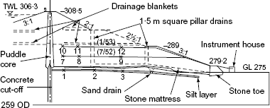
Early construction work at Usk revealed a layer of silt at a depth of about 3 m below ground level, and a spread of investigative boreholes at 30 m centres showed that it extended under the position for the downstream shoulder. At that time, engineers regarded silt as a very treacherous material that could lose strength very easily. Clay was φ = 0 material with a measurable shear strength, and sand was a reliable material with values of φ that could be measured. But silt behaved as a c, φ material of variable properties and would be unsuitable in the foundation of a major dam. Mr Sheppard, the partner responsible for Usk, was aware from the paper by Cooling and Golder3 of the analysis made by Skempton of the strength increase of the clay layer under the Chingford dam caused by consolidation, and the remarks made by the authors that there might be problems when, with a more permeable foundation layer, such as one of silt, it might be possible to rely on an increase in shear strength during the normal construction period. He wanted to apply that principle to the silt layer under Usk, rather than have to dig it out. I went with him to the site, where we took a sample of the silt by hand in a U4 tube that we carefully dug out, rather than use any twisting or pulling. We brought it back to the laboratory surrounded by cushions in the middle of his car so as to minimise disturbance. I made a series of oedometer tests immediately (a Saturday and a Sunday: I lodged with the Burns at the BRS Gate House Lodge), and designed a layout of sand drains to relieve any excess pore pressures that could develop in the silt layer, using the method given by Barron.4 A spacing for the sand drains of 30 m centres would have been suitable, and I suggested that the exploratory boreholes used to find the extent of the silt layer could be backfilled with sand, but unfortunately each had been fully backfilled with clay to seal against possible future water movements and to prevent damage to roaming farm animals. As an alternative, I designed a line drain to be under the position for the first berm, consisting of a trench taken down to within about 15 cm of the silt layer, with hand-drilled holes of 20 cm diameter at 3 m centres from the bottom of the trench, taken down to just below the bottom of the silt layer. These were backfilled with sand, brought up to form a layer about 30 cm thick in the bottom of the trench, which was then backfilled with stone rubble to join with the stone drainage mattress that was placed under the whole of the downstream shoulder. To check on the performance of this line drain, I placed six piezometer intake filters in the silt layer midway between the drainage trench and the central cut-off of the dam, in July 1951. They were connected by 5 mm plastic tubing, laid in the trench, to a concrete instrument house built on the natural ground just below the downstream rock toe of the dam. The gauge board was made by BRS workshops for 12 piezometers, because I had in mind to seek permission to place some intake filters in the fill of the dam. Mr Sheppard readily agreed to this, so when in July 1952 the fill had reached about the midway level of that year's placing season, I placed three intake filters on the major section, as shown by Fig. 1. After installing these three piezometers, taking zero readings and instructing young Bill Carlyle, an engineer on the resident engineer's staff, how to take and interpret readings, my wife and I set off on our Norton motorbike for our annual holiday on the continent. When we came back, a month later, I was met, when I went in to BRS, by Cooling, who said that Binnie's were very concerned that my piezometers were showing pore pressures greater than the added overburden pressure, and that the Bourdon gauges had all gone beyond the ends of their scales with the pointers close to the stops. I ordered new gauges of greater range and went to the site to see what had happened. The gauge boards had a mercury manometer to check the calibration of the Bourdon gauges, which were found to be correct. They had scales in lb/in2 but the conversions to feet head of water had been made correctly, so it seemed that the pore pressures really were high. To use modern terminology, the ru values were in excess of 150%, but fortunately the placing season was coming to an end, when there would be a winter period for dissipation to occur.
During the winter of 1952–53 we carried out an extensive series of triaxial tests on samples of the fill from both dams, which showed that, at the placement water contents and densities, low pore pressures were to be expected at Daer but quite high ones at Usk, although the reason for ru values greater than 1 could not be explained. We made very many stability analyses using the method of slices so that we could allow for pore pressures—that is, effective stress analyses—and found that the pore pressures would have to dissipate to an ru value of no more than 40% for stability. By February the pore pressures were clearly not going to dissipate sufficiently, and Binnie Deacon and Gourley called in Drs Skempton and Bishop at Imperial College for a second opinion. They had 15 steel standpipe piezometers designed by Stanley Serota driven into an adjacent section during the spring of 1953, both upstream and downstream of the central core. Water rose in them to several metres above fill surface (tall decorators' step ladders had to be used to measure the levels), confirming the BRS measurements and showing that the high ru values were general. Similar standpipes were placed at Daer: they remained dry, and added water quickly drained away!
The remedial measure suggested was to place filter drainage layers over the surface of the first and then, later, the second year's fill, thereby reducing the length of the drainage paths from the three almost equal thicknesses of fill that formed the whole dam height. This technique had recently been used in the 50 m high Harspranget dam described by Westerberg et al.5 It led almost to a fashion of using drainage layers, and many subsequent dams had drainage layers built into them during construction.
The reason for the high pore pressures at Usk was that a very large scraper, which had been imported for open-cast mining, had been used during that first placing season. It not only raised the fill very quickly, but also took the surface and therefore wettest fill from the borrow pits in this region of high rainfall. As remedial measures additional to the filter/drainage layers, for the second and third years the big scraper was replaced by face shovels to win drier fill from the borrow pits by working from almost vertical faces, as in a quarry, transporting it to site by dump truck and spreading with bulldozers. It can safely be said that, without the facility of pore pressure measurements, this dam would have failed before it reached full design height. This experience reinforced the position of the soil mechanics group at BRS as being in the forefront of research into embankment dams, and the group's advice was sought widely. The story of the construction of these two dams and the pore pressures measured has been told by Penman.6
4.2.3. Other dams and embankments
The experience of Usk aroused considerable interest in the use of effective stresses in stability analyses and the need for field measurements of pore pressures. BRS advice was sought in the cases of several dams including, by 1956, the 34 m high Sasumua dam in Kenya; the Ajena dam on the Volta river; Glen Shira in Scotland; Chew Stoke and Sutton Bingham dams, both 13 m high with central puddled clay cores in the west of England; Hanningfield and Foxcote dams; plus a road embankment, the foundation for an oil tank, a trial embankment for the extension to the Hong Kong airport runway and a 5·5 m high flood bank on the Wadi-Tharthar in Iraq. In 1953, an unfortunate combination of an exceptionally high tide and a strong north-east wind built up a surge in the southern North Sea that overwhelmed flood banks in Holland and south-east England. There was extensive flooding, and the government asked BRS to help with assessing the causes of failures of the flood banks and to advise on their reconstruction. Arthur Marsland was put in charge of this work, as described below.
4.2.4. The problem of ru > 1
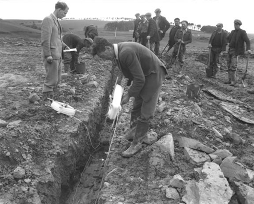
The additional problem of the pore pressures being greater than the overburden pressure was particularly intriguing because it is known that pore pressures in clay fills must initially be well below atmospheric pressure to provide the effective stress needed to give the fill the strength to support the placing and compacting machinery. It was thought that high lateral pressures might have been developed in the fill by the weight of the compaction machines, so tests were made at both Usk and Daer to check this effect. The intake filters were placed in the usual way in trench, as shown by Fig. 2, which was backfilled while being lightly compacted, and then fill was spread to provide a cover of about 60 cm before being heavily compacted by machine. At Daer, compaction by a loaded Euclid with tyre pressures of 414 kN/m2 caused a pore pressure increase of only 3·4 kN/m2, whereas at Usk compaction by a D8 bulldozer with a track pressure of 68 kN/m2 caused a maximum pore pressure increase of 35 kN/m2. After compaction, the small amount of overburden over the intake filters produced a maximum ru = 1·27. During the next four months this did not dissipate below ru = 1.
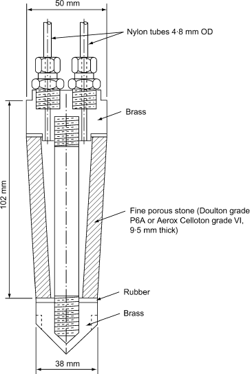
It is evident that an intake filter must be strong enough not to be affected by total pressures, and it must be fine enough to exclude the finest particles of the fill, yet allow pore water to pass in sufficient small quantities to operate the pressure-measuring part of the piezometer. The filters at Usk were carborundum discs made for us by a grinding wheel company, and were relatively permeable. Cooling, from his experience with building stones and the use of the suction plate apparatus, suggested that, if pore water suctions were to be measured in partly saturated fill, the pores of the intake filter should be small enough not only to exclude soil particles, but also to exclude air. Owing to surface tension and curvature of the meniscus in a partly saturated fine grained soil, the pressure of air in the pores is greater than that of the water. If the pores of the intake filter would not exclude air, as with the Usk piezometers, then the higher air pressure from the partly saturated fill would be measured. For the filter to be successful in keeping out air, and hence measuring the pore water pressure, it should have uniform sized pores that were sufficiently small. The effectiveness of the filter in keeping out air can be expressed by the differential pressure needed to force air into a saturated filter. The Usk carborundum stone had an air entry pressure of only about 3·5 kN/m2 and so could not be expected to exclude air from the fill. A search was made for a more suitable filter material, and a porous ceramic was found with a permeability of 2·910−6 cm/s, which had an air entry pressure of over 200 kN/m2. The manufacturers were persuaded to make conical shapes for use in a new design of fine pored intake filter described by Bishop et al.,7 shown in Fig. 3. It has a larger intake area of about 152 cm2, and the conical shape enables it to be pressed into a tapered hole to make good contact with the fill. It has become the type generally used with hydraulic piezometers.
4.2.5. Selset dam
The 39 m high Selset dam was one of the next large dams to be built after Daer and Usk in Britain. Like Usk, it had a central vertical puddled clay core, and shoulder fill of boulder clay, which was at about its optimum water content as dug from the borrow pits. During the construction season from April to October, rainfall of about 510 mm was expected, so it was accepted that the fill would be placed wet of optimum. To avoid the high pore pressures of the Usk dam, and following the remedial measure used there, filter drainage blankets were proposed. Calculations based on the consolidation properties of the compacted boulder clay showed that horizontal blankets would be required at a vertical spacing of 4·6 m. Because of the probability of a higher permeability in the horizontal direction caused by placement in layers, vertical wall drains were proposed at 15 m spacing in the horizontal direction along the dam axis. These were constructed by trenching through the first 1·5 m thickness of fill to contact the bottom drainage blanket, and repeating the trenching after each additional 1·5 m of fill had been added, so as to contact the lower vertical drain. A combination of the retarding effect on construction, and the true need for them, judged from the piezometer results studied during the first winter shut down, caused these vertical wall drains to be abandoned after the first, 1957, placing season. The dam was completed during the next two seasons, 1958 and 1959. Most of the piezometer intake filters were the same as those used at Usk, with coarse stones of 20·3 cm2 area. Because of the low air-entry pressure of only about 3·5 kN/m2, the initial suctions were not measured, and it was difficult to maintain an air-free system. The first of the new, conical-shaped intake filters had been made by the middle of the 1959 season, and five of them, using the new nylon connecting tubes, were placed: two in the fill and three in the puddled clay core. Negative pore pressures of 55 kN/m2 were measured, and trouble with air became negligible. The stiffer nylon tubing plus the larger filter intake area reduced the t90 response time from about 1000 min for the earlier piezometers with polythene connecting tubes to 180 min.
It was observed that the polythene connecting tubing, when containing water at below atmospheric pressure, slowly accumulated air bubbles, and laboratory tests revealed that the walls of the tube were permeable to air, although completely impervious to water. Nylon, on the other hand, as well as being much stiffer, was completely impervious to air. It, however, absorbed water, which could evaporate from the outside, so that it slowly lost water. The solution was to have the nylon tube coated with polythene, forming what has become the standard connecting tubing for hydraulic piezometers. Nylon 66, which was used at first, formed crystals in contained water, and nylon 11 has been found to be the best for this use.
A new settlement gauge consisting of steel plates 30 cm square, with central holes that were fitted over a vertical plastic tube and placed at intervals during fill placement, was first used at Selset in the core. The plates were subsequently detected by an induction coil lowered inside the tube. Using a standard inductance bridge, the value of the coil was set with it between plates and the positions of the plates determined from the out-of-balance effect as the coil passed through them. Two of these gauges were installed, and revealed the interesting behaviour of the puddle clay core.
4.3. Third International Conference
It had been agreed at the first Conference that subsequent conferences would be held every four years. Wartime conditions postponed the second Conference, and the third was to have been held in 1952, but, to avoid a clash with other conferences, it was arranged for 1953, and was held between 15 and 20 August in Zürich. There were 67 British delegates, including L. F. Cooling with his wife, A. D. M. Penman with his wife, Joyce, and W. H. Ward from the Section, plus S. J. Button, then with Ground Explorations Limited, and G. G. Meyerhof, who had joined the Foundation Company of Canada (the firm made famous by their righting of the failed Winnepeg grain silo in 1911). Twenty eight papers were submitted from Britain, four of these from BRS. Géotechnique provided a new outlet for soil mechanics papers, and some from BRS in 1953 had been published there. During discussion in Zürich I had been able to present some of my work of measuring pore pressures in Usk dam,8 which aroused considerable interest. It was decided that, in four years' time, the fourth Conference would be held in London.
4.4. The next four years
BRS received an urgent request from the Ministry of Agriculture and Fisheries for assistance with soil mechanics problems arising from damage to the sea defence banks on the East Coast following the abnormal tidal surge that occurred during the night of 31 January–1 February 1953. Marsland was put in charge of this work. He took the mobile lab and became deeply involved in the investigation of failures and the design of remedial works. He found that many of the banks failed before being overtopped, with a rotational slip on the landward side due to the rise of the phreatic surface and/or the increase of pore pressure under the landward toe due to transmission through sandy layers, leading to the type of failure observed in the Thorpe March flood bank. Many of the flood banks had not had any appreciable depths of water against them for a long time, and so had been dried out by weed roots, like the King George V dam in the Lea valley, discussed earlier. When the flood waters rose, the phreatic surface was quickly pushed to the inland slope, many of which failed before the flood waters overtopped the crest. Some of these cases were described by Cooling and Marsland.9 The government offered a 100% grant for rebuilding the banks within a year. Contracts were let rapidly, but rapid rebuilding, usually to a slightly greater height, often led to another failure. The existing banks had been built slowly over the soft marshland, and rapid construction gave no time for the dissipation of construction pore pressures. Wide landside berms were used to regain stability, but the extra land take was not always possible. Eventually the mistake of excessive speed was accepted, and a steadier programme of rebuilding and generally raising the heights of all the banks was adopted. Marsland conducted a full-scale overtopping test on a section of existing flood bank by building a basin on a 60 ft (18·2 m) length of a redundant part, by constructing a steel sheet pile cofferdam on the river side and pumping sea water into it to simulate a rising tide, but continued to the point of overtopping. The bank was fully instrumented, floodlights and cine cameras set up, before water was pumped into the basin. Failure occurred when the water level had almost reached the crest. The resulting damage was limited, because the basin was not of large volume. This full-scale experiment confirmed that the bank failed by rotational slip on the land side, the slip removing more than half the width of the crest, leaving a vertical face at the crest 2·5 ft (0·76 m) deep. The remaining thin barrier soon gave way, forming a 2·5 ft (0·76 m) deep breach, which began eroding badly before the cofferdam emptied.
A new form of precast concrete tunnel lining had been developed and was being use for a 9 ft (2·74 m) diameter water tunnel for MWB being constructed in London clay at a depth of 90 ft (27·4 m). Each ring of the lining was formed with taped segments, which were pressed into place by the hydraulic jacks used to advance the shield, so that the ring expanded onto the clay surface, producing a prestress to resist the pressure from the clay. Extensive measurements were made of the hoop stresses developed, using vibrating wire load cells, and of the changes of tunnel diameter caused by the internal water pressure when the tunnel was put into use. A special vibrating wire gauge was made with a diving bell attachment to keep the air pressure in the gauge at the water pressure. Application of 100 ft (30·4 m) head of water pressure caused an increase in diameter of only 0·01 in (0·25 mm), which did not remove the compressive prestress in the concrete lining, showing that the external clay pressure exceeded the water pressure so that there was no need for expensive tensile lining. Another tunnel to carry water mains under the River Clyde was being constructed under compressed air. Instrumentation included 100 vibrating wire gauges, connected via electromagnetic selector switches and a five-conductor cable to the surface so that they could be read at any time, without having to enter the compressed air zone. The prototype stable oscillator set was sent up there for this work, and was taken over by the soils group at Glasgow University. The measurements showed clearly that stresses were affected by the tide in the river above, but the greatest stresses were caused by caulking the flange joints with lead.
In cooperation with the Piling Committee of the Institution of Civil Engineers, we began a special study of the bearing capacity of pile foundations, and Whitaker transferred from the concrete section to take charge of this study of the design and behaviour of piles. He used model piles in dry sand and later in clay, and designed small piles with miniature proving rings to measure both the total loads on them and the skin resistance on their shafts. He tested square groups of 9, 25, 49 and 81 piles at 1·5, 2, 3 and 4 diameter spacing and of length 24 and 48 diameters. He found that efficiency dropped when the piles were closer than 3d, and that a group at 1·5d spacing in clay failed as a block. Considering the distribution of load-carrying capacity, he found that the corner piles carried the greatest load; less was carried by each pile progressively with its position towards the centre of the group, the central pile carrying least load. He described this work in a paper to Géotechnique.10
Solution cavities in chalk, which have formed over periods of thousands of years, can cause swallow holes at the surface when the overburden collapses into them. The parents at a Buckinghamshire school had clubbed together to build a swimming pool. They did much of the work themselves and provided their big concrete pool with a soakaway close to the deep end to take the water when it was emptied. Because of the pool, they were able to attract an inter-schools sports event to their school. In preparation they emptied the pool to carry out minor repairs, refilled it to test that everything was all right, emptied it again and gave it a final clean just before the event. Filling, through a small hose, took a long time, and the hose was left running overnight so that the pool would be full of fresh water for the event day. But when they came next morning, the deep end wall had moved out and the pool was empty. A swallow hole had formed around the soakaway. The cause was the release of water into the overburden, which had weakened it, allowing it to fall into a cavity that must have existed for a very long time. Finding solution cavities is difficult: site investigations using boreholes can easily miss them.
The BRS work on foundations for houses on shrinkable clays had been of great help to the postwar schools programme in the design of foundations for these new light-framed buildings. A further problem was construction over mining areas where subsidence waves were caused by long wall mining in which the cavity left by the extracted coal is allowed to close as the long wall cutting machinery and conveyer belts move forward. BRS suggested that the schools should be made to comply with the ground subsidence, and a design was developed with a light steel frame with sprung diagonals and overlapping cladding wall panels so that the building could distort without damage. The foundation was kept on the surface and consisted of a thin raft resting on a bed of sand to allow sliding, to avoid transmission of horizontal ground strains to the building. The first school was completed without any additional expense in providing this subsidence protection.
4.4. Fourth International Conference
BRS undertook a major part in the technical editing of the approximately 180 papers of the two-volume proceedings. Whitaker was put in charge, and we took on the first Mrs Taylor as his secretary. It was the first time that the Section had had a secretary, and although Mrs Taylor worked exclusively for the Conference, the idea of a secretary for the Section remained. Previously all typing had been done in the typing pool, with resulting delays of several days, or possibly weeks by the time corrections had been made. Having an efficient secretary within the Section made a vast difference.
The Conference was held in the building of the Institution of Civil Engineers in London from 12–21 August 1957, and it was noted that this period covered the 200th anniversary of the birth of the Institution's first President, Thomas Telford. Terzaghi had been President of the International Society since its formation, and handed over this prestigious position to Dr Skempton (now the late Sir Alec), making him the second President of the Society. About 40 countries were represented by 772 delegates, including 307 from Britain. Those from the Section included R. W. Cooke, L. F. Cooling with his wife and daughter, Christine, A. Marsland, A. D. M. Penman, W. H. Ward and T. Whitaker. R. E. Gibson, who had been for a few years in the Soils Section at BRS, attended from Imperial College, where he was working with Skempton and Bishop. S. J. Button, then with Taylor Woodrow Construction Limited, was there, as was T. K. Chaplin, who had left the Section in April 1956 to join the soil mechanics group at Birmingham University. The proceedings were divided into nine sessions, with many of the Section's staff assisting with the running and organisation. Delegates were able to visit seven fully equipped soil mechanics laboratories, including that at BRS.
4.5. Conclusion
Research in soil mechanics carried out at the BRS has had a major influence in the development of the subject in Britain. It began in a small way with the experimental work to determine earth pressures against retaining walls carried out by Professor Jenkin in 1929, as a continuation of work he had started at Oxford, but the next 28 years saw huge developments. The subsequent 45 years up to the present (2002) have seen even greater developments, but are within easy living memory and may form the subject of a future essay. BRS, started as a research station of the Department of Scientific and Industrial Research, came under the new Ministry of Technology when it was formed, and from there became part of the Department of the Environment. In March 1997 BRE was transferred to the private sector, and is now a wholly owned subsidiary company of the Foundation for the Built Environment. The Foundation is a non-profit-distributing body having the legal status of a company limited by guarantee. The ownership structure was created to maintain BRE's independence from specific commercial interests and to protect its reputation for objectivity and impartiality in research and advice.
4.6. Acknowledgements
I am grateful to Mr I. K. Nixon for allowing me to use his biographical note on Professor Jenkin and to access his file, to Dr Sills for arranging access to the Jenkin Library at Oxford University, to Professor C. B. Crawford for information about the Annual Canadian Geotechnical Conferences, to Professor G. G. Meyerhof for historical information, and to Dr J. A. Charles, Head of the Geotechnics Division at BRE, for valuable constructive criticism of this essay, and permission for its publication.
REFERENCES
BIBLIOGRAPHY
A biography of G. G. Meyerhof can be found in a book published by the Canadian Geotechnical Society as part of the Jubilee Celebrations in 1997 (Geotechnical News Special, October 1997, p. 39).
Selected Papers on Soil Mechanics by A. W. Skempton FRS, published by Thomas Telford, London, 1984, contains a Chronology.
Obituaries published in Géotechnique include:
L. F. Cooling (1903–1977), 27, No. 2, 265–270 (shows a photograph of the stable block where Jenkin worked)
A. W. Bishop (1920–1988), 38, No. 4, 653–655
H. Q. Golder (1911–1990), 41, No. 3, 475–477
W. H. Ward (1917–1996), 46, No. 3, 576–585
A. W. Skempton (1914–2001), 51, No. 10, 829–834.