J. A. Knappett, University of Dundee
Representing the pile stiffness in terms of Ep and not EpIp has led to misleading values of shear forces, moments and displacements being presented in the design charts.
The bending stiffness of simple elastic solid circular section beams as presented in the original paper assumes that the neutral axis for bending passes through the centre of the cross-section, and that tensile and compressive forces are resisted on either side of this axis.
For unreinforced concrete sections, however, the tensile capacity will be small or negligible, such that equation (2) will overestimate Ip (and therefore also EpIp) by a factor of 2. Furthermore, the bending stiffness of both unreinforced and reinforced concrete piles will depend on the depth of the neutral axis within the section, which is in turn dependent on the axial load and bending moment carried by the pile.20 This may be accounted for, however, by using the interaction diagram for a concrete section to determine the neutral axis depth (and, additionally, the ultimate moment capacity). A better estimate of the bending stiffness of the cracked composite section may then be found using classical elastic (transformed area) theory.20
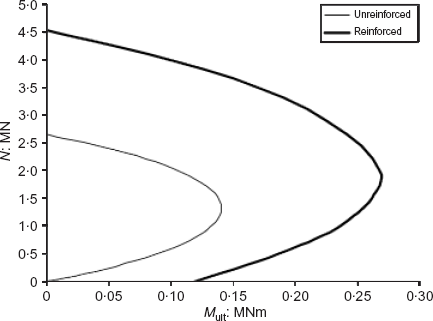
As an example, both a reinforced and an unreinforced pile section have been compared with linear-elastic solid beam assumptions under the following conditions: FS = 3, L = 10, Es/cu ≈ 1000. The reinforcement layout was kept the same while the diameter of the piles was increased, and consisted of eight longitudinal mild-steel bars of 20 mm diameter spaced equally around the pile section. The design cube strength of the concrete in both cases was fcu = 30 MPa, and the Young's modulus of the concrete was assumed to be 30 GPa, as in the original paper. Interaction diagrams for the two sections are given in Fig. 13.
The maximum working axial load (P) has been calculated using equation (3), where Nc = 9, cu can be determined from Es, as suggested in the original paper, and α is given by equation (4).
In equation (4), A = 0.5 for normally consolidated soils (2cu/γ′L < 1) and A = 0.25 for overconsolidated soils (2cu/γ′L > 1), as presented by Randolph and Murphy.21
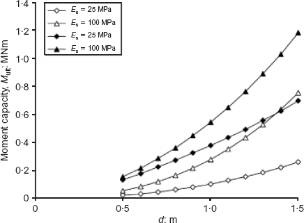
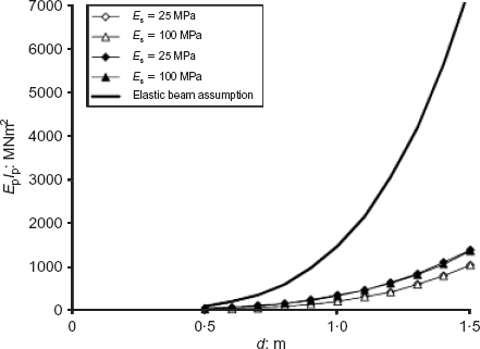
Figure 14 shows the moment capacities of the section (Mult) at the interpolated values of P. Estimated cracked-section values of EpIp are presented in Fig. 15, along with values assuming an elastic solid circular beam assumption (equation (2)).
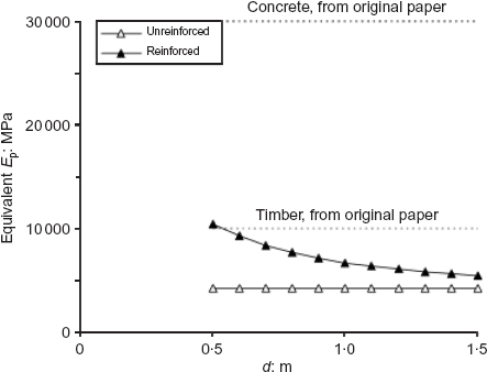
The calculated EpIp values have been divided by values calculated using equation (2), to calculate the equivalent solid section bending stiffness of the two pile sections applicable to the design charts in the original paper. These are shown in Fig. 16. The actual values of EpIp for the concrete sections are much lower than those from equation (2), and are closer to the value given for the ‘timber’ piles in the original design charts. The dynamic bending moments and shear forces will therefore be correspondingly lower and the displacements potentially larger.
This discussion has demonstrated that it is more appropriate (and accurate) to express pile bending stiffness in terms of EpIp and not just Ep. The discusser feels that the method outlined in this discussion would provide a valuable way of determining bending stiffnesses for concrete piles prior to undertaking finite-difference analyses as outlined in the original paper. However, owing to the wide range of possible values of EpIp for concrete piles (depending on reinforcement layout and loading conditions), the discusser questions the usefulness of the design charts (as presented) in assessing the maximum response of concrete piles.
Authors' reply
The authors agree that the design charts would have been enhanced in generality had not the implicit assumption been made that Ip = πd4/64, and that expressing the results in terms of the bending stiffness of the pile, EpIp, rather than the Young's modulus of the pile material, Ep, would have been preferable. While the implicit assumption of elastic pile behaviour is reasonable for timber piles (or steel tube piles using an equivalent pile modulus), it is clearly deficient for concrete piles, where cracking can alter the section properties of the pile during the loading process. In fact, for such piles, one really requires an analysis where the non-linear pile behaviour is reflected by having a modulus that changes during the loading process, rather than having a single value of Ep.
Since results in the paper are given for two values of Ep, 30 000 and 10 000 MPa, one possible means of making some allowance for the cracked section is to compute the pile response for both values of Ep, and then interpolate between them for an equivalent value of pile modulus, Epe, such that Epe = Ep.Ip.64/πd4, where EpIp is the estimated actual bending stiffness of the pile. Because only two values of Ep have been considered, the interpolation process will clearly be approximate, but should nevertheless give answers that reflect somewhat more closely those for the cracked section properties of the pile.
The discusser's comments draw attention to the more general problem of laterally loaded pile analysis, in which similar simplified assumptions are usually made about the linear structural behaviour of the pile. Some analyses do now allow for non-linear pile behaviour to be modelled—for example, Kramer and Heavey.22