Contribution by P. C. F. Ng
Gallage et al. (2012), report on more research on the understanding of soil-pipe interaction problems, but extensive research on this area has been conducted worldwide. Much of the early research in the UK was carried out by British Gas (e.g. Needham and Howe, 1981).
Shrinking/swelling soil coupled with temperature and seasonal groundwater level changes had caused many failures of the older pipe systems in the UK, mainly the cast iron pipes with lead–yarn joints. This is one of the reasons why British Gas instigated the use of polyethylene (PE) pipe to overcome this problem, as PE pipe is very flexible, and able to tolerate large differential ground movement before failure.
It would be useful if the authors' paper gave more information on the pipe materials used in the Australian water and gas networks. This could in some way explain why the research examined the behaviour of PE pipe rather than that of cast iron pipes.
The elastic properties of PE are highly influenced by temperature, rate of loading and age, as the short-term and long-term properties are very different. The paper did not give details of the temperature and loading rate of the three-point loading test, or whether they match those in the model box test. Therefore it would be useful if the properties determined for the numerical model (i.e. Young's modulus of 700 MPa) could be justified.
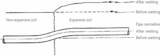
The experimental work carried out has provided some important data for benchmarking their numerical model. While the set-up of inducing soil swelling worked well, the use of a 2 m PE pipe restrained at both ends is somewhat idealistic, and may not reflect a realistic situation in the field. A more creditable situation to examine would be as a pipeline crosses from a region of non-swelling soil to a region of swelling soil, as illustrated in Figure 23.
It is also unclear why a soil restraint model for sand (Cheuk et al., 2005) was adopted in the numerical procedure, rather than a suitable model for clay. Full-scale soil–pipe interaction experiments have previously been carried out as part of an international collaborative research project, as reported by Ng et al. (2001). Methods such as NEN3650 (NEN, 2006) and ALA (2005) have been used worldwide for predicting upward soil restraint in clay.
It is unfortunate that the strain gauges on the pipeline had malfunctioned, and only deflection results can be used. Although the experiment had successfully demonstrated that soil swelling could cause a PE pipe to deform, the corresponding bending stress was unknown. Therefore the pipe owner's main concern – whether the pipe stress is acceptable – appears to remain unanswered.
One of the recent directions in the water and gas industries is to use probabilistic analysis to predict pipe failure within a network, so that resources can be targeted to higher-risk areas (NRC-IRC, 2009). The numerical model developed in the paper might form an integral part of such a statistical/probabilistic analysis.
Authors' reply
The pipe materials used in the water and gas network in Australia are mainly cast iron, steel, polyethylene (PE) and PVC. Statistical analysis on the current pipe assets in Australia has shown that 40% of cast iron and 41% of PE pipes are used in retail water and gas reticulation systems (Chan, 2008). Most of the old pipes are cast iron, and they are commonly buried at 0·6–1·0 m depth, which is within the reactive soil depth for many areas of Australia. Significant numbers of cast iron pipe failures have been reported in summer and winter (Ibrahimi, 2005; Jarrett et al., 2001; Kassiff and Holland, 1965), and it was identified that seasonal ground movement (shrinking/swelling) coupled with soil temperature had caused these failures (Chan, 2008; Chan et al., 2007; Gould, 2011). PE pipes are commonly used for new installations by the Australian water and gas authorities, as these pipes are more flexible than cast iron pipes, and better performance is expected when they are buried in reactive soils.
It is understood that the elastic properties of PE change with temperature, age and rate of loading. The three-point loading test was conducted to obtain the short-term elastic properties of the PE pipe. The test was conducted at room temperature of 25°C, which is similar to that applicable to the soil box test. The loading rate applied during the three-point test was approximately 0·2 N/s. Although the rate of swelling was not measured in the soil box test, it was considered that temperature effects and loading rate effects are negligible. The model box test was conducted for about 4 months, and the effect of age on the elastic properties of the buried PE during this timescale was considered insignificant (e.g. Ahn, 1998). Therefore the measured Young's modulus of 700 MPa was considered appropriate, and was within the values reported by the pipe manufacturer.
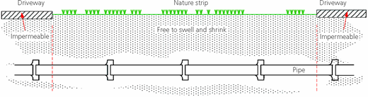
The authors acknowledge that the experimental set-up using limited pipe length with restraint at the end of PE pipe may not be entirely realistic in practice. However, the intention of the test was to simulate a soil–pipe interaction in a reactive soil medium and then use these results for numerical modelling (see also Rajeev and Kodikara, 2011). Most parts of the Australian water and gas reticulation pipe network are laid in a nature strip that runs next to the roadways. As shown in Figure 24, concrete driveways are commonly constructed to provide access into the buildings, and many failures are concentrated close to the edge of the driveways. In this scenario, the pipe between the two driveways can be considered to be restrained at both ends, since the soil under the driveways is less likely to undergo swelling/shrinking deformation. The authors instrumented one in-service water pipe and one in-service gas reticulation (cast iron) pipe to monitor the behaviour in such field scenarios. The data from these two sites have been collected for about 2 years, and have confirmed this mechanism. The results of these field experiments will be reported in forthcoming publications.
The Cheuk et al. (2005) model was used, since it is applicable to predict the ultimate state of uplift resistance of clay by assuming zero dilation and friction angles for clay soils during undrained failure. The authors accept that the malfunctioning of the strain gauges attached to the pipe was unfortunate. Although direct calculation of stresses during stress development was not possible, the measurement of pipe deflection allowed the calculation of stresses at the final state for comparison with numerical results. The authors agree that the developed models can be used in physically based probabilistic models on reticulation pipe failures. Such analyses could be considered superior to pure statistical analyses relying entirely on past failure data.