N. R. Somers, ICE, UK
Having attempted to recreate the spreadsheet in Table 1, I believe there may be a typographical error in the column for F′s. The column is based on equation (14) of the paper with the value of ζ and a′ as given in the table (0·851 and 0·127 respectively). Thus, for example, if t = 0 then, from the equation, 1/2[ζ(1 – t)+ a′] = 0·511.

The column should be, I believe, as follows
0·511
0·535
0·560
0·588
0·619
0·653
0·692
0·735
0·784
0·840
0·905
0·981
1·070
1·177
1·309
1·473
1·684
1·966
2·361
2·954
3·947
Please can you confirm my understanding.
Authors' response
The authors thank the contributor for having discovered a mistake in the spreadsheet, and apologise to Geotechnical Engineering readers for that. There was an error in the transcription (not seen) of equation (14) in the column of F′s in the block ‘Plots’. This has been corrected in Table 1 and Fig. 3, and there are no more changes in the paper, as the results of the worked example do not change. The authors have dared to take advantage of this mishap to present, in Table 1, the latest, improved version of the spreadsheet. With this improved version, paragraph (c) in section 7 should read as follows.
(c) The minimum b/√K value of the envelope will correspond to the optimum design. The spreadsheet will translate this minimum value to the Min b/√K′ cell in the ‘Results’ section using the function Min. The corresponding t value will be translated to this column, using the function Search, which will look for the value in the ‘Envelope’ column that will match the value under Min b/√K′, and then will seek the corresponding value in the t column of the ‘Plot block’.
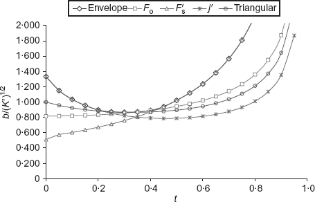
Curves corresponding to the safety factors against overturning and sliding, allowable bearing pressure indicated in Table 1, and triangular distribution, including the envelope of these curves
Curves corresponding to the safety factors against overturning and sliding, allowable bearing pressure indicated in Table 1, and triangular distribution, including the envelope of these curves
If the optimum toe projection is not convenient, the spreadsheet might help to find another solution falling in the envelope. In order to do so, successive b/√K′ values are copied from the ‘Envelope’ column and stuck (special stuck: values) in the selected b/√K′ cell of the ‘Results’ column. The corresponding t value is obtained anew using the Seek function. The process is followed until a convenient toe projection is found.
The earth pressure coefficient in L-shaped walls is usually calculated according to Rankine theory, Kar, and this is done under the ‘Aid for initial data calculation’ block. However, the spreadsheet allows the introduction of other coefficients, for example the coefficient of earth pressure at rest, if wall and foundation are very rigid, so that K must be introduced by hand in the ‘Initial data’ block.
Very often the angle of friction at the base, δ, is given as a ratio, δ/Φ′, of the angle of internal friction, and adhesion as a ratio, a/c, of soil cohesion.3,4 The block ‘Aid for initial calculation’ allows calculation, in this way, of both a and μ = tan δ.
It must be remembered that all values in the grey cells in the sheet must be introduced by hand, although some of the values in the ‘Initial data’ block might be taken from the ‘Aid for initial data calculation’ block.
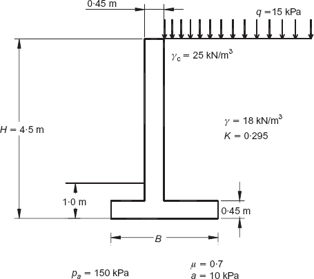
The authors have since noticed an error in Figure 4: the fill unit weight should be 18 kN/m3 instead of 10 kN/m3 and the corrected Figure is included here.