
The paper discussing a proposed method for evaluating the tensile stresses induced in geosynthetic components by cover or waste placement along the slope is indeed very interesting, and a step forward from the limit equilibrium method(s). The design charts are very appealing, as they expedite the design calculations and reduce the inefficiency of using numerous formulas if several construction steps are involved. Furthermore, all the terms adopted using the graphical method are dimensionless, and therefore lead to a generic design that can be adopted conveniently by practitioners.
However, it needs to be clearly stated that the example given using the graphical method (e.g. design chart and proposed equations) is relatively conservative compared with the use of the full equations in Liu and Gilbert (2003), because the cohesion and/or adhesion parameters are ignored. Although the contribution from the cohesion of the cover soil could be insignificant for the calculation of tensile stresses in the geosynthetics, the contribution of apparent adhesion for interfaces between geosynthetics is quite significant, especially for the cover soil design. Additionally, ignoring the interface adhesion (e.g. at the upper interface) in multi-layered lining systems can result in underestimation of the tensile stress in a lining component located above the critical shear plane.
Furthermore, the formulation for the dimensionless term, ϕnet, in Equation 8 is clearly simplified when water flow is considered. The occurrence of water flow decreases effective normal stress and increases the shear stress (Giroud et al. 1995). Therefore, by dividing the net shear stress by the applied stress from the soil when water flow occurs yields the following:
where λ = tw/t, Γ = γw/γ, and κ = γsat/γ. (It should also be stated that γ is the bulk unit weight of the cover soil.) If there is no water flow in the cover soil, and hence no drag force exerted from the flowing water (i.e. Γ = γw/γ, κ = 1), Equation 12 would yield Equation 8 given in the paper. It is proposed that Equation 12 is a more general and useful solution for calculating the dimensionless coefficient ϕnet.
Finally, the length of the system, L, should be clarified, as it is required for derivation of the formulation (Equation 3). The distance between the toe at the base (buttress) and the anchorage at the top of the slope should be between two constraints where displacements are restricted, as shown in Figure 10.
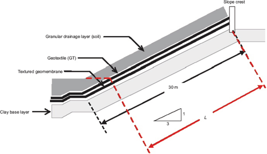
Geometry and material properties for landfill slope example (modified from Liu and Gilbert 2005)
Geometry and material properties for landfill slope example (modified from Liu and Gilbert 2005)
Response
We should like to thank the discussers for offering insightful comments and providing a productive discussion. The discussers point out that the intercept (cohesion or adhesion) term in Equation 4 may be important in estimating tensile stresses. We agree entirely, and do not intend the use of a secant friction angle in Equation 5 to imply that the intercept term is zero. We intend that the secant friction angle in Equation 5 be selected to give the correct shear strength at the effective normal stress acting on the interface. We should like to emphasise that the appropriate secant friction angle to use in the non-dimensional solutions may change if the effective normal stress changes: for example, one may need to use a different value of the secant friction angle when water pressure reduces the effective normal stress at an interface.
The discussers point out that infiltration of water into a cover soil may increase the total unit weight of the soil, and provide a revised version of Equation 8 to account for this effect. In Equation 8 in the paper this effect is accounted for in the total unit weight term γ, which is used to calculate Γ. If the total unit weight varies over the thickness of the layer, then an average value should be used for γ. As a simple example, if the total unit weight in the soil is equal to the dry unit weight, γdry, in the soil above the water table and equal to the saturated unit weight, γsat, in the soil below the water table, then the average total unit weight for the layer would be γ = [γdry(t – tw) + γsattw]/t. In this simple example, the same result would be obtained using either Equation 8 in the paper or the revised version proposed by the discussers (Equation 12), provided that γdry is substituted for γ in the discussers' version. We should like to emphasise that this simple example and Equation 12 presented by the discussers are not necessarily general; the total unit weight of a fine-grained layer may not change due to water infiltration because it may be saturated before the infiltration event even if the water table is at or below the base of the layer.
The discussers are correct that L in this paper is the distance along the slope between fixed-end constraints, such as anchor trenches or benches.
