CONTRIBUTION BY D. LESNIEWSKA
I would like to make some comments in relation to the paper by David Muir Wood (Muir Wood, 2012), who, in my opinion, asks certain questions of great importance to the foundations of modern geomechanics.
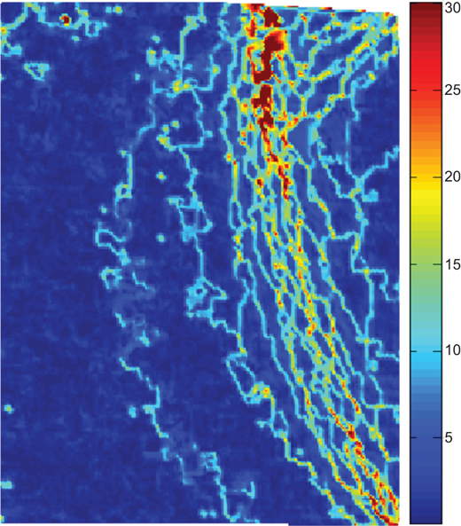
Firstly, I would like to support his thesis of a spontaneous regular heterogenisation being common in granular materials and to draw attention to the great variety in this phenomenon. The example presented in Fig. 12 shows a net-like pattern emerging from a shear strain map produced by particle image velocimetry (PIV) for a test on a vertical model wall. The wall was moving horizontally away from a relatively loose mass of glass granules. One can see that the course of the future ‘single shear band’ expected in such a case can be followed from the locations of the maximum shear strains, but it starts to build using convenient pieces of some finer localisations, jumping from one to another and thus acquiring quite a complicated internal structure.
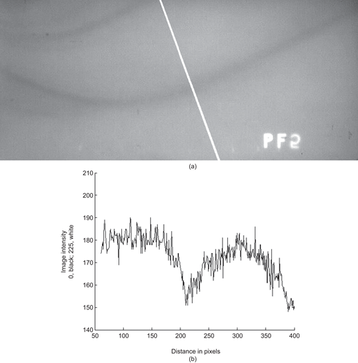
My second comment relates to the identification of the edge of a dilation band. Figure 13(a) is a part of one of the radiographs recorded by Bransby in 1968 (test PF) and shows at least two well-developed single dilation bands, recorded at the final stage of passive wall movement into a mass of sand (Bransby, 1968). Figure 13(b) shows the image intensity variation along the white line marked in Fig. 13(a). A lot of local density fluctuations, related to the granular nature of the sample, are superimposed on the main trend, suggesting that the material density within the ‘single shear band’ is by no means constant – it rather seems to change symmetrically in relation to the centre of the band and dies out at some distance, as suggested by Muir Wood. Perhaps the answers to some of the unanswered questions concerning granular materials are still hidden in the Cambridge radiographs, if they could be systematically analysed with modern techniques that were non-existent when they were created.
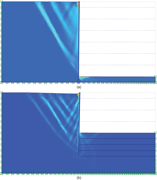
As to the question of what ingredients of constitutive models tend to lead to regular patterning in granular materials, Fig. 14 shows the final results of a finite-element simulation of soil excavation from one side of a flexible wall using Plaxis. The wall height is about 5 m and the soil parameters are typical for a medium-dense sand (Mohr–Coulomb model). The only difference between Fig. 14(a) and Fig. 14(b) is the angle of soil dilation, which is equal to the soil internal friction angle in the first case and zero in the second. In light of what is shown in Fig. 14, what is the purpose of sophisticated soil models – to explain the mechanism of soil localisation or to make it more visible? The shear strain increments in Fig. 14(a) clearly show not only strain localisation but also traces of regular patterning for the standard Mohr–Coulomb soil model – if this is the case, isn't it possible that patterning comes directly from the general minimum energy principle, which is also the basis of the finite-element method and no special model ingredients are needed?
AUTHOR'S RESPONSE
I am grateful to Dr Lesniewska for her supportive comments on my letter relating to three aspects – spontaneous regular heterogenisation, identification of dimensions of dilation bands and patterning of localisation in numerical analysis.
It is clear from her observations that the behaviour of granular materials at scales of a few particle diameters is complex and discontinuous. Some of the features in Fig. 12 have the appearance of artefacts of the algorithms used for calculation of strains or forming the contour plot – the ‘threads’ of shear strain look curious. The patchy form of the eventual region of high shear strain is, however, clearly evident. What is the size of the particles in relation to the size of this image?
Full-field techniques such as radiography – the source of Fig. 13 – provide a store of data that can be inspected and studied over the years at different levels of detail. The limit to the detection of variations is provided by the graininess of the photographic film – is it possible that some of the ‘high-frequency’ variations of image intensity shown here may be at the scale of this graininess? However, the measurements support the notion that the boundaries of such dilation bands cannot be precisely located.
Finally, Fig. 14 shows the results of finite-element analysis of a classical earth pressure problem performed using Plaxis with a Mohr–Coulomb model with angles of dilation equal to the angle of friction and to zero. It is suggested that nothing more than such a Mohr–Coulomb model is required to produce regular patterned localisation of shear strains. I am not an expert in numerical analysis of this type, but I am uneasy about the results shown. There is no intrinsic length in the Mohr–Coulomb model, so it is difficult to see what aspect of the constitutive model itself might be controlling the spacing of the bands that can be seen. Is the patterning insensitive to the arrangement and size of the finite-element mesh? Minimum energy principles may well govern the choices that the soil makes, but I think that my question concerning the necessary features of constitutive models for prediction of patterning and for controlling the dimensions of such patterning remains unanswered.