Professor Schofield discusses two issues: (a) the peak strength of remoulded overconsolidated fine-grained soil and its post-peak behaviour; and (b) the inclusion of interlocking (dilatancy) in plastic design strength. The critical state framework embraces the state boundary surfaces on the ‘wet’ and ‘dry’ side, with the critical state line acting as a ‘watershed’ between the two. It has brought a most valuable coherence to the understanding of the mechanical behaviour of soils. Its practical value is enhanced if its limitations are understood as well as its many advantages.
Professor Schofield argues that the Hvorslev cohesive intercept for remoulded overconsolidated fine-grained soils results from interlocking, or the rate of dilation, rather than from cohesion between the soil particles. While this interpretation seems reasonable, it still requires experimental verification. Also, an explanation is needed as to why, prior to the formation of slip surfaces, undrained (constant volume) stress paths rise to the same Hvorslev bounding surface as drained tests that are dilating (see Fig. 8·13 of Schofield & Wroth, 1968).
The uniqueness of the critical state line for a given soil is a concept that is based on the results of experiments on granular soils and on remoulded clay soils (Roscoe et al., 1958). A close study of the 1958 paper reveals how circumspect the authors were in putting forward this hypothesis for heavily overconsolidated clay soils. They stressed the inconclusiveness of the experimental evidence, which was due to the limitations of the triaxial test, the relative magnitude of the corrections that had to be applied at the low stresses involved, and the difficulty of determining the moisture content in a localised thin region of concentrated shearing—a point emphasised by Professor Schofield in his letter. The discussion that followed the publication of the 1958 paper concentrated on the interpretation of the experimental evidence for critical states for clay soils on the ‘dry’ side.
In the time since the publication of the 1958 paper the influence of the structure and fabric of clay soils has been studied extensively. For remoulded fine-grained soils there is evidence to suggest that, within a localised thin layer, progressive orientation of clay particles can take place, resulting in stress ratios that fall below critical state values and culminating in residual strengths. For example, the discusser presents experimental and microscopic evidence for the formation of thin slip surfaces in an undrained test on remoulded normally consolidated kaolin in which a significant reduction in stress ratio takes place subsequent to the formation of the slip surface (Burland, 1990, Figs 45–47). The fact that clay particles can orientate progressively during shearing is undeniable, and the possibility of this occurring within a thin layer of gouge cannot be overlooked. It is not obvious that a soil element within such a thin slip surface must pass through a critical state (in p′, q, e space) prior to the particles within it commencing progressive orientation. Thus the critical state line appears to form a useful target, but the discusser believes that it would be wise to retain the caution that was evident in the original 1958 paper, in the light of recent understanding of the influences of structure and fabric.
The influences of structure become particularly significant in natural soils that have both bonding and fabric. The critical state framework for reconstituted samples of the soil provides a valuable frame of reference for understanding and interpreting the effects of structure for the natural soil (Burland, 1990).
Can dilatancy be included in plastic design strength? Professor Schofield argues that it cannot, and recommends using CS friction in limiting equilibrium design methods. The logical conclusion seems to be that, for granular materials, we should ignore the very significant increases in the peak angle of shearing resistance that increases of density give. Geotechnical engineers and clients would need much convincing if this suggestion was implemented for the design of foundations, retaining walls, tunnels and—to a lesser extent—slopes, as the cost would be significant. An important factor that seems to have been largely ignored in the debate about the use of critical state strengths in design is the rate at which strength reduces beyond peak, and hence the assessment of the potential in a given problem for progressive local failure to take place during or subsequent to loading. Such an assessment is problem and soil dependent, and the writer urges caution in the use of blanket assertions about the use of critical state strengths in design. There is also a need for guidance as to how precisely the critical state line and critical strengths should be determined in natural structured soils.
Professor Schofield raises interesting questions on the nature of the strength of fine-grained soils, and on the selection of strength parameters for design. In this contribution I should like to add some practical considerations, and one further question.
Professor Schofield's question (a) refers to remoulded, reconstituted soil. In practice we often deal with soils that are ‘undisturbed’, in the sense that they have not been remoulded or reconstituted. Examples would include the foundations of many structures, which essentially rest on only undisturbed, in situ material. In other cases we deal with material that is partially disturbed, such as when stiff or hard clay is trucked to a site and compacted as a foundation material or an embankment. For some of these materials a 20% shear strain may perhaps not be sufficient to achieve the same kind of remoulding, but might well constitute ‘failure’ in an engineering sense. In Trinidad and other tropical regions there are highly structured clays formed by the weathering of rock. Offshore, worldwide, it is common to find ductile clays whose remoulded strengths may be one half of their undisturbed strengths: the undisturbed strengths are typically used in offshore pile design. Tailings dams retain fine-grained materials formed from mechanical-chemical processes. They may be very different from inert, remoulded, reconstituted ‘laboratory’ soils.
It would be very interesting to this reader if the following additional question could be considered: (c) for practical limit state design, how relevant are the general conclusions that can be drawn from data for inert, remoulded, reconstituted fine-grained soils, and what additional considerations may be needed?
I have two answers to Professor Schofield's questions: (a) the ‘peak strength’ results from critical shearing resistance and dilation; and (b) the dilation part can get lost, and should therefore not be taken into account in the assessment of stability.
The effective tensile strength of soils is negligible, at least in the common range of mineral particles, ionic strengths, pressures and void ratios. If mud is consolidated to 1 MPa and exposed to water with the same pH and salt it will soften. The excess of van der Waals' attraction over electro-osmotic repulsion is negligible in the geotechnical regime. Terzaghi and Hvorslev assumed that interfering bound pore water glues clay particles together, but this is not the case. Bridges can form during times of rest, but they break with minute deformations, and cannot be reconstituted within geotechnically relevant deformation times.
As long as the degradation of mineral particles may be neglected, monotonic undrained (constant volume) deformations lead to critical states on the wet side of critical. The direction or obliquity of the skeleton stress tensor is determined by the critical friction angle ϕ′c. The asymptotic or critical p′ is determined by e, and by the rate of dilation rate. This non-linear viscosity is due to thermally or seismically activated dislocations in the case of soft or hard particles.
Critical states are thus undrained or constant-volume state limits. They can also be attained by monotonic constant stress deformations (i.e. if p′ is kept constant). If the initial e exceeds ec for the given p′, a representative soil element can undergo a uniform contractant deformation until a critical state is reached. With e < ec initially the representative soil element tends to a peak of deviatoric stress and to localised dilatant shearing. In shear bands the skeleton tends to a critical state for the given p′ and rate of dilation. With given effective stresses the skeleton moves towards a critical state. At subcritical states the soil becomes denser: in super-critical states the soil dilates, accompanied by critical phenomena such as shear localisation and/or cavitation.
These behaviours can be captured by constitutive relations that are more or less validated. Except for viscosity and some streamlining, the essential features are already embedded in CSSM. Critical states are thus the backbone of soil mechanics, and they define stability in the civil engineering sense of stability, that is, the ability to stand. So-called plastic limit states are necessary but, in general, not sufficient for stability. In the case of dead loads, representative soil elements with constant stress and overcritical obliquity dilate owing to thermal and microseismic activation. In a composite of representative soil elements, such as in a finite element model with initial and boundary conditions, the matter is more complex, with redistributions of stresses and pore pressures. Critical phenomena are progressive, so that peak and critical states in the large cannot be identified in general.
Any assessment of stability for design requires statical and kinematical simplifications. These must not be at variance with CSSM and its modern extensions. Plastic limit states have to be justified, and can by no means always serve to the purpose. One should not forget Darwin's (1883) ‘historical element’, which in his opinion eludes mathematical treatment. In other words, ‘failure mechanisms’ cannot arise from nowhere, and cannot take the place of physically sound prediction models. Atavistic requirements in codes of practice, such as ‘resistance must exceed action by a factor of safety’, have little to do with stability. As outlined by Atkinson (2002), they hinder physical understanding.
There is further discussion on critical states with viscosity in Gudehus (2008).
Professor Schofield raises two very important questions relating to the interpretation of peak soil strength in his letter. There is a school of thought that continues blindly to accept the representation of peak strength as the sum of Terzaghi's ‘true’ cohesion and ‘true’ friction without realising that these two parameters are not material parameters but empirical coefficients describing the intercept and slope of the straight-line approximation of strength envelope over a limited range of stress.
Over half a century ago, Taylor (1948) claimed it to be a poor policy to use the terms ‘cohesion’ and ‘friction angle’ in an empirical sense for such intercept and slope coefficients. He went on to state that these empirical coefficients are not constant soil properties, but depend on the state of the soil, and vary over wide ranges for a given soil under various possible combinations of precompression, drainage, and other variables (Taylor, 1948, pp. 401–404).
It is now known that the shear strength and deformation behaviour of soil are very sensitive to the combination of changes in volume and the confining stress. Depending on their combination, a soil aggregate may fracture and crack into clastic debris, or fail with fault planes on which gouge material dilates and softens, or it can continue to yield and deform plastically. Strength representation based on Terzaghi's interpretation could not distinguish between these distinct classes of soil behaviour, and thus led to many of the difficulties that researchers are faced with relating to the interpretation of geotechnical failures such as liquefaction and earth dams.
The critical state soil mechanics representation of soil strength as Taylor's sum of interlocking and ultimate critical state drained friction is a fundamental paradigm shift, which initially was a challenge to the grasp of some. Gradually the ideas became well established, and now form the core understanding of how soils behave as engineering materials. This strength representation can be used to interpret many of the geotechnical failures with clarity (Muhunthan & Schofield, 2000). A succinct account of this strength representation and applications of the critical state framework to geotechnical practice is presented in Schofield (2005).
The original critical state concepts were based mainly on the behaviour of essentially reconstituted isotropic materials. Further experimental information has proved that the behaviour of natural soils, especially sands, with pronounced microstructural anisotropy deviates significantly from the premises of critical state soil mechanics, resulting in questions such as the existence and uniqueness of the critical state line. While they have all been discussed extensively, there is still no universal agreement on the answers.
Of particular interest to the correspondents are Professor Schofield's remarks relating to work, energy and dissipation. Specifically, the issue that some of the ‘interlocking work’ need not be dissipated, but can be ‘stored’ and recovered, has been central to our recent attempts to use energy arguments and modern formulations of thermomechanics to derive constitutive models for granular materials (Collins & Muhunthan, 2003; Collins, 2005; Collins et al., 2007).
Energy arguments were used by Schofield and other members of the Cambridge group in their analyses, leading to the derivation of the models now known as ‘Original and Modified Cam Clay’. These arguments were in line with those currently being employed in metal plasticity, utilising concepts such as Drucker's postulate and normal flow rules. It is now evident that these arguments must be modified in the light of recent advances in our understanding of the thermomechanics of elastic/plastic materials (Collins & Kelly, 2002), and if the models are to truly represent materials with a granular microstructure. These arguments invite two important corrections, as discussed below.
The early analyses equated the increment of plastic work to the increment of dissipation. In other words, it was assumed that all the plastic work is dissipated. This is not true, even for metals. The rearrangements that occur at the micro scale, as a result of plastic deformations at the macro scale, cause some of the elastic energy stored at the micro level to be ‘trapped’, ‘frozen’ or ‘blocked’. This energy is not recovered under elastic unloading at the macro level. Instead, reversed plastic loading is needed to free this energy. At the level of a few hundred grains the stress and strain distributions are highly inhomogeneous, as a result of the formation of strong (force chain) and weak networks. This has been demonstrated by numerous DEM and photo-elastic simulations. As discussed in Collins (2005), and in the references cited in that paper, these meso-level inhomogeneities give rise to the missing stored plastic work increment term in the energy balance equation. No energy is frozen in a shear deformation. It is present only in compactive or dilative deformations: in the latter case it is negative, as frozen energy is being released.
The recovery of frozen elastic energy is only one mechanism for plastic volume change. The second mechanism relates back to the early experiments of Reynolds (1885), who demonstrated that shear deformations of granular materials induce volume changes. This is very similar to the concept of ‘interlocking’ introduced by Taylor (1948). Taylor's calculations of the associated interlocking work increment did not distinguish between the two distinct sources of volume change in granular materials, nor point to the possibility that one of them leads to zero work constraint. The latter component is the defining feature of granular materials, identified by Reynolds, that separates them from other engineering materials.
Consider an assembly of perfectly smooth, rigid grains. There is hence no mechanism for frictional dissipation (either by sliding or by rolling), and no mechanism for energy storage. In order to get the assembly to shear, and the grains to move over each other, the applied work has just to overcome gravity and inertia. However, these two factors are small, and are neglected in analyses of laboratory tests. In an engineering model this extra term is hence zero valued. The positive shear work exactly balances the negative work done against the confining pressure.
The applied plastic work increment is hence equal to the sum of the increments of dissipation (which cannot be negative), the stored plastic work (which can be positive or negative) and the constraint work increment (which is zero valued).
For illustrative purposes consider the situation in conventional triaxial tests, where, using the standard notation, we can write the energy dissipation relation as
where δWP is the increment of plastic work, δΦ is the dissipation increment, δWS is the increment in frozen elastic energy (stored plastic work), and δWC is the zero-valued ‘constraint work’, arising from the granular nature of soils.
Since we have identified two mechanisms of volume change, we must define two plastic volume increments: , which arises from (effective) stress changes, and would be present in a non-granular material; and , which is induced by the shear deformation, and is a characteristic of granular materials. Thus the increment of total plastic volumetric strain can be written
Similar decomposition of plastic volumetric strain increment has been done in the past under various contexts, but none recognised Reynolds's effect as an internal constraint (e.g. Vermeer, 1978; Chandler, 1985; Shamoto & Zhang, 1998). The ratio of the induced volume increment to the shear strain increment defines an induced dilation angle θ, where
The standard (total) plastic dilatancy angle ψ is defined in terms of the total volumetric plastic strain rate, so that
and
The various terms in equation (1) can be expressed in terms of the appropriate strain increment and its work conjugate stress. In particular, the shear stress q has to be regarded as the sum of two terms: qD, which is the shear stress that produces frictional energy dissipation; and qR, the reaction shear stress that is needed to drive the particles over each other against the applied pressure p. Since this latter process involves no work, it follows from equation (3) that qR = p tan θ, so that the stress ratio can be written
The first term on the right-hand side corresponds to Professor Schofield's ‘frictional strength’ associated with the frictional resistance to sliding and rolling between the grains, and the second term is the ‘apparent interlocking strength’ arising from granular structure. Since θ depends on the configuration of the sand grains, but not on their frictional properties, the induced part of the stress ratio would be unaffected even if the interparticle friction were changed. This was observed experimentally by Skinner (1969) and confirmed recently by discrete element simulations, for example Kruyt & Rothenberg (2006).
Of particular interest is the particular state in which the stress-induced volume change is zero, in which case the stored work is constant and all the dissipation is due to shear, so qD = Mp and θ is now equal to ψ, the total dilation angle. In this state,
This state may usefully be termed the ‘Reynolds–Taylor’ state, since the only mechanism for dilation is that described by Reynolds and termed ‘interlocking’ by Taylor. This state is observed after 2% or 3% strains in conventional drained tests for sands (Muhunthan & Olcott, 2002; Collins et al., 2007). It is a generalisation of the critical state concept, but differs in that the granular assembly is still dilating. Ultimately, however, the induced dilation must cease, and θ and ψ are both zero; the ‘apparent interlocking strength’ disappears; and the conventional critical state is achieved at very large strains.
The deeper analyses of these models are presented in Collins & Muhunthan (2003), Collins & Tai (2005) and Collins et al. (2007), who show that the deformation and stress states predicted in such a model are anisotropic. As well as producing dilation, the shear of granular materials also necessarily induces anisotropy. This fact is well established by micromechanical simulations (Oda, 1993), but is frequently ignored in analyses. In the discusser's view, much of the uncertainty surrounding issues such as the existence, uniqueness of critical state and macroscopic critical state strength stems from the discussions being cast in an inappropriate isotropic framework. Our research shows that Professor Schofield's vision of using critical state friction and interlocking is far reaching, and that it can be extended in a systematic manner once allowance is made for the development of anisotropy.
Authors' reply
My letter raised two simple questions for discussion.
First, is peak strength (i) Terzaghi's sum of cohesion and friction, or (ii) Taylor's sum of friction and interlocking? My answer was that (ii) Taylor was right.
Second, can interlocking be included in plastic design strength? My answer was that it must not be included.
Fifty years ago, when Roscoe et al. (1958) published the critical state (CS) concept, we saw ‘remarkable similarity between the behaviour of clays and cohesionless granular media’, and proposed that many soils had CS lines. My letter, based on this concept, argued that Hvorslev's cohesive intercept for overconsolidated fine-grained remoulded soils does not result from cohesion between the soil particles but from the rate of dilation (Taylor's interlocking).
Burland comments: ‘While this interpretation seems reasonable it still requires experimental verification’. Our 1958 discussion on clay soils said the triaxial test data on the dry side of CS were inconclusive. Burland asks why, prior to the formation of slip surfaces, undrained (constant volume) stress paths rose to the same Hvorslev bounding surface as drained tests that are dilating. Our paper Roscoe et al. (1958, section 2(d)) suggested that no work is dissipated in volume change. If distortion increments require the same power in an undrained or a drained test then both test paths reach the same surface. Thurairajah (1961) verified this, calculating the work balance in each step of triaxial test paths. His test analysis showed that the work absorbed internally is independent of the rate of dilation (the basis of the original Cam-clay (OCC) model). Neither a triaxial nor a simple shear specimen is soil in the uniform state of ‘a failure surface at the moment of failure’. Schofield & Wroth (1968) explained the care needed where a specimen was initially under virgin compression, where theory predicts a singularity, and experimentally we cannot expect that the stress ‘is an absolutely uniform effective spherical pressure’. Students may not get uniformity in test specimens, and successive students may verify different concepts, as Walker (1965) verified modified Cam-clay (quoted by Roscoe & Burland, 1968), and OCC was verified both by Loudon (1967) (quoted by Schofield & Wroth, 1968) and by Lawrence (1980) (quoted by Schofield, 2005). The CS concept got conclusive support from plasticity index and fall-cone test data (Schofield, 1966; Schofield & Wroth, 1968). When a pallet knife is used to mix soil and water for classification testing, it becomes a CS paste. The CS concept applies to the soils Casagrande classified. The Imperial College triaxial tests were not intended to turn soil into a paste; even so, as Parry's (1958) test paths ended, they were approaching the final CS line from either the wet or the dry side. Is more verification required?
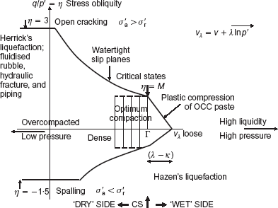
Professor Burland's comment that the CS framework (Fig. 2) ‘has brought a most valuable coherence to the understanding of the mechanical behaviour of soils’ is welcome. That particular framework made no reference to tension cracks in soil on the dry side of CS. Cracking was shown in Fig. 10·2 of Schofield & Wroth (1968). In the frontispiece of Schofield (2005) (Fig. 3 below), cracks play a major role in soil behaviour on the dry side of CS. Other aspects of the mechanical behaviour of soils in this frame that one reviewer has noted include ‘the plastic compression of soil specimens that are wetter than critical, the occurrence of slip planes, cracking and spalling for heavily overconsolidated clays, and even liquefaction, piping and hydraulic fracture’ (Nova, 2006). Gudehus and Muhunthan & Collins agree with my answer to my second question, that plastic design strength of soil should not include dilation; the intercept AB in Fig. 1 is not reliable cohesion. Burland considers that ‘geotechnical engineers and clients would need much convincing’ that they cannot rely on cohesion; I think that such people need to get experimental verification of cohesion.
It is a ‘basic concept’ of CS soil mechanics (Schofield & Wroth, 1968) that perfect laboratory tests of soil samples with ‘microscopic fabric’ are not needed in plastic design. We wrote:
Suppose we have a soil with a measured peak strength which (a) could not be correlated with index properties, (b) was destroyed after mechanical disturbance of the soil fabric, and (c) could only be explained in terms of this fabric. If we wished to base a design on this peak strength, special care would be needed to ensure that the whole deposit did have this particular (unstable) property. In contrast, if we can base a design on the macroscopic properties of soil in the critical states, we shall be concerned with more stable properties and we shall be able to make use of the data of a normal soil survey such as the in situ water content and index properties.
The CS frame considers disturbed soils as classified by Casagrande's system. When the US Army Engineer Corps selected soil to build levees or embankment dams, or form roads and airfields, they got soil with robust grains that survived excavation, transport from borrow pits and the process of compaction to form earthworks. The CS concepts that apply to ‘selected’ soil explain that, when under stress, it should be in an ‘optimum compaction’ state, as shown in the CS frame when it is under working loads. Overcompaction of soil brings with it a risk of a soil body cracking into permeable rubble.
However, 50 years ago the main challenge for CS theory was not interpretation of tests but the ‘liquefaction problem’. Cam-clay is a stable contractive soil that contradicts Casagrande's dictum that contractive soil liquefies. CS concepts were unacceptable until we had data for earthquake generation of pore water pressure. It was conventional wisdom that insight into liquefaction would come only from full-scale experience. Small-scale model testing in geotechnical centrifuges was a possibility, but Terzaghi had derided it as ‘utter futile’; UK geotechnical research funds went to full-scale tests in the field. However, CS concepts suggested that models made of disturbed soil would show correct failure mechanisms and pore water pressure generation in earthquake tests. Centrifuge operation was costly, but over 20 years several problems that were too dangerous to study at full scale were solved for industry at small scale on contracts using a series of centrifuges. Publications such as Lee & Schofield (1988) led Schofield (2005) to discuss new liquefaction concepts and set them in the fuller CS frame above. This is not analogue modelling, in which a continuous body of soil is represented by elements of an analogous material: each finite physical element of our models was made of reconstituted soil; each was as big as a triaxial test specimen. The element boundaries fitted each other, and their pore fluid pressures and soil and water movements correctly represented those in the full-scale problem. For a client dealing with some dangerous problem it is an attraction of such tests that they can be made safely, in confidence, and in time to make a design decision.
On the second of my two questions relating to plastic design strength, Burland asks whether very significant increases in the peak angle of shearing resistance given by increases of density must be ignored. Centrifuge model tests allow them to be considered. Malushitsky's tests (Schofield, 2005, 6·3) let mine waste heaps be cut back to slopes more steep than would be allowed by a ‘safe’ soil mechanics calculation. The tests allowed safety authorities to reduce the environmental impact of the works and to save cost to the client. A geotechnical engineer or client for an embankment such as Teton Dam will not need convincing that the soil must not be in a brittle state with high peak strength, low ductility, and cracks that do not self-heal (Schofield, 2005). It was a fatal flaw in the construction of Teton Dam that the compacted core soil ductility was greatly reduced by heavy compaction. In Fig. 3 the words ‘optimum compaction’ advise that soil should be compacted to a density at or slightly above the critical density for the working value of p′. Soil in this state is a tough, plastic material. The fuller CS frame applies to soil without structure or fabric that (in the words of Rankine, 1857) could be called ‘a mass composed of separate grains’ with stability that arises ‘wholly from the mutual friction of those grains and not from any adhesion amongst them’. Natural undisturbed ground is a soft rock with aggregate ‘bonding and fabric’, but soil on the dry side of CS fails both with slip surfaces and also with tension cracks, and breaks up into blocks of rubble, becoming heterogeneous and not moving uniformly to the CS line on the Hvorslev surface as envisaged in 1958.
Dean asks how the CS concept applies to undisturbed soil in practice, and mentions offshore soils. In analysing both stability and serviceability designers can benefit from the rational thinking of plastic analysis (Osman et al., 2006). As we gained confidence in geotechnical centrifuge model testing, my Manchester University colleagues Rowe & Craig (1976, 1978) pioneered the design of foundation systems with models, testing schemes for the Oosterschelde Barrier at an early enough stage to introduce major alterations of the design. The method has been used to model other offshore foundation systems. Tests can be part of a design process using data from previous similar work, geological survey, soil sampling and testing, and both simple and detailed computation. This may extend into observation in construction and operation after completion of work, if the owner agrees. Such model studies may be most important for novel schemes, where there is no previous experience of similar work or of the mechanisms of ground displacement. Engineers could make more use of centrifuge tests and predict ground behaviour at full scale from an aggregate of grains in a model. Instead of using soil element test data in FE computations, they can regard each finite element of a model as an appropriate soil-test element. Models made from large blocks of undisturbed soil have been used in successful centrifuge tests. Large equipment that is used in construction can retrieve large soil samples and, if tests are well planned in advance, such models could assist trial construction, or improve use of the observational method, on a large project at a low cost.
Gudehus gives welcome support to my answer to my second question, but I am unsure about his suggestion that rate of dilation and non-linear viscosity are important. CS theories are elastic-plastic, not viscous. In centrifugal model tests two timescales are considered, and neither allows for a viscous property of soil: in earthquake models the vibration frequency is increased with length scale n; time is scaled by n2 in modelling diffusion. If significant creep continues in any viscous ground, it will come to have a level surface. Where a landform shows evidence of events long ago, as in erosion of a valley, the ground is not viscous. Schofield (2005, Fig. 63) shows termination of creep: a skeleton of highly loaded interlocked hard grains can carry a long-term load. Geotechnical design can trust both the mechanisms seen in centrifuge model tests and the plastic theory in analysis, because aggregates exhibit ultimate plastic strength that is due not to clay surface physics and pore-fluid chemistry but to solid interactions in the stressed grain aggregate.
Muhunthan and Collins also give welcome support to the CS concept, and concepts that are linked in Fig. 3 above, but I am unsure about the details of their energy arguments and modern formulations of thermomechanics from which they derive constitutive models for granular materials. Can plastic deformations in new experiments at the macro scale cause elastic energy stored at the micro level to be ‘trapped’, ‘frozen’ or ‘blocked’? Can reversed plastic loading that freed this energy show that energy is frozen in volumetric deformations but not in shear deformation? Can grains with a range of sizes corresponding to the MIT grain sizes be used in DEM simulations? Sand in an hourglass will ultimately flow in shear, with only elastic-mechanical interactions between grains: such grains are not ideal spheres, like the cannonballs stacked in Coulomb's seventeenth-century forts. When pinched hard in their flow history, strong grains will be knocked into shapes without sharp corners, and weak grains will shatter. Observation of the evolution of grains in CS flow might lead to new shapes being developed for simulations in which aggregates might dissipate work in distortion as in Thurairajah's function, yield at a stress ratio below CS if contractive, sustain a stress ratio above the CS value if dilative, and have a CS line with dry states on one side and wet states on the other side. Micromechanical study of an aggregate of grains on the dry side of CS, held in a volume of space by effective stress, might show progressive failure on slip planes. New grain-aggregate tests that verified Muhunthan and Collins' concept of stored plastic work might also demonstrate shear of granular materials necessarily inducing anisotropy as well as producing dilation.