
The writers agree with the authors that upper bound methods have much to offer in the general field of stability analysis, in spite of the fact that they yield values of safety factor, F, equal to or greater than the mathematically correct value for whatever definition of F has been adopted and may therefore be considered somewhat unconservative. However, experience to date has shown that correctly programmed and applied upper bound slope stability methods usually provide answers within 0·02 of the actual value, where this is known accurately, and therefore well within the acceptable practical range of error. Apart from a limited number of idealised problems for which the ‘correct’ answer is available from plasticity theory, some other approach is needed to provide referee values against which practical methods may be measured, and currently finite element analyses provide the best access to referee answers for comple, realistic situations. However, such analyses are not yet popular with practitioners, since they require reliably accurate solutions with a minimum of data input fuss and time delay, and fortunately alternative upper bound solutions meeting these requirements are available.
Two upper bound solutions developed at Monash University (Giam & Donald, 1991)—GWEDGEM (General WEDGE Method) and EMU (Energy Method Upper-bound)—have been used to analyse the authors' four example problems for purposes of comparison, and the results are presented below. GWEDGEM (Donald & Zhao, 1995a) is a multi-wedge analysis based on force and moment equilibrium, while EMU (Donald & Chen, 1998) uses the energy balance equations of upper bound plasticity theory, and although the methods of analysis are very different they may be shown to be theoretically equivalent and therefore both upper bound analysis. Both programs are equipped with efficient critical failure mechanism search schemes requiring minimal data input for the initial trial surface; GWEDGEM even includes an option for selecting an initial trial failure mechanism automatically. GWEDGEM and EMU normally give almost identical values of F for a wide range of problems (Donald & Giam, 1989); Donald & Pitsch, 1997).
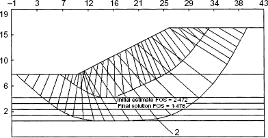
For Example 1 the authors present a range of values as summarised below: to be compared with Conventional vertical slice methods can give values less than the correct value by up to 0·05, and it is not certain whether they are providing upper or lower bound solutions, but this could explain the difference between 1·44 and 1·48 GWEDGEM and EMU are giving upper bound values 0·03 to 0·04 higher than Jiang & Magnan, with failure mechanisms that are not simple rotational ones agreeing closely with the movement vectors in the authors' Fig. 4, and it would be interesting to use the finite element analysis results in alternative ways−for example the nodal displacement method (Donald & Giam, 1988) or a mobilised stress method such as CRISS (Donald 1994) to provide additional comparisons.
| F = 1·45 | Low |
| F = 1·44 | Bishop (simplified) |
| F = 1·48 | Jiang & Magnan |
| F = 1·44 | Low: Jiang & Magnan (hand calc.) |
Examples 1, 2 and 3 share a common feature that makes accurate calculations of safety factor difficult: the presence of a top soil layer with significant cohesive strength. The inclusion of tension cracks in the analyses will make interpretation difficult, yet many conventional analyses mask this effect by not warning the analyst that the solution as delivered implies tensile strength in the upper sections of the profile. GWEDGEM warns when tensile forces occur between wedges, and EMU presents graphical and tabular outputs of stresses on sliding interfaces, so the analyst may insert a suitable depth of tension crack into the data file, though the correct depth and number of cracks to insert is open to argument. It would be interesting to know what patterns of tensile stresses emerged from the finite element analyses and whether some form of automatic crack propagation could be included readily. Using 2·2 m deep crack or cracks, without water, in Example 1 gave F = 1·43 and 1·44 for GWEDGEM and EMU respectively.
In Example 2 the cohesive strength of 95 kPa for the top 8 m of the profile greatly increases the difficulty of providing a unique value of F. In summary: The wide range of values gives cause for concern, and probably reflects mainly the actual or implied handling of tensile stresses or forces by the different methods of analysis. The GWEDGEM analyses using force and moment equilibrium tended to oscillate between 1·48 and 1·26–1·22 as the geometric search routine moved the potential failure mechanism in and out of critical tensile stress areas, but using the program's option for the well-known Sarma approach gave only the higher value of F, agreeing with the EMU answer. These discrepancies raise important questions, and the matter is under further investigation.
| F = 1·378 | Low: semi-analytical |
| F = 1·36 | Fellenius |
| F = 1·25 | Jiang & Magnan |
| F = 1·14 | Low: Bishop |
| F = 1·48 to 1·22 | GWEDGEM |
| F = 1·48 | EMU |
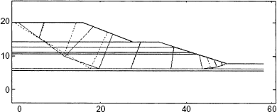
If 7 m deep tension cracks are included, the safety factor values drop to 0·99 (GWEDGEM) and 1·00 (EMU), and if the whole of the upper layer is treated as a strengthless surcharge the values become 0·82 and 0·79 respectively, with the failure mechanism being a bearing capacity failure near the toe. For the intact slope with no tension cracks both programs indicate significant tensions in the top layer, but the failure mechanisms again agree excellently with the movement vectors in Fig. 8 of the paper (Fig. 17.)
For Example 3 the summary of results is: The methods of Jiang & Magnan, GWEDGEM and EMU give close agreement to two decimal places; their results are therefore identical for practical purposes. The failure mechanisms for GWEDGEM and EMU agree extremely well with the movement vectors in the authors' Fig. 12, particularly the almost horizontal movement of a large block of soil below the berm (Fig. 18) It is interesting to note that, according to GWEDGEM analyses, regardless of berm width the critical condition is actually local failure at the level of the top berm with F = 0·938 for a 2 m crack!
| 6·1 m berm | |
| F = 1·0 | Skempton |
| F = 0·905 | Jiang & Magnan |
| F = 0·899 | Chen/Bishop |
| F = 0·864 | Chen/Morgenstern & Price |
| F = 0·888 | GWEDGEM |
| F = 0·884 (with 2 m dry crack) | |
| F = 0·899 | EMU |
| F = 0·890 (with 2 m dry crack) | |
| 12·2 m berm | |
| F = 1·2 | Skempton |
| F = 1·007 | Jiang & Magnan |
| F = 1·068 | Chen/Bishop |
| F = 0·974 | Chen/Morgenstern & Price |
| F = 0·988 | GWEDGEM |
| F = 0·978 (with 2 m dry crack) | |
| F = 1·005 | EMU |
| F = 0·995 (with 2 m drv crack) |
Example 4 is a significantly different problem, with a more complex failure mechanism than the slope problems, yet again all three numerical upper bound methods yield excellent answers: and failure mechanisms extremely close to the Prandtl solution. The authors comment on the lack of evident relationship between Nq and Fs, yet a reasonable functional relationship is obtained by plotting the results in their Table 1, noting that for purely cohesive soils Fs and the ratio of foundation ultimate bearing capacity to applied stress are equal, whereas for frictional soils this is not true unless both values are 1·0. For example, given a strip footing of width 2·5 m, c = 20 kPa and ϕ = 20° we find that a load factor of 2·70 corresponds to a safety factor on strength of 1·47, both figures being in the typical ranges expected in bearing capacity and slope stability contexts respectively (Donald & Zhao, 1995b).
