

As with slope stability, there are many papers written on the determination of active and passive earth pressures under static and dynamic conditions, and the authors have contributed one more and have compared the results of their procedure with those of others for homogeneous, cohesionless backfill. In general, the new results are about the same as the results previously reported by others using acceptable procedures. For passive earth pressures, when the angle of wall friction is large, the use of Coulomb's plane sliding surface is known to be on the unsafe side, and its use in engineering practice is not recommended; instead, the use of a curved sliding surface is the norm. Also, the sliding surface is more curved in the passive case than for the active case. This means that the use of planar sliding surfaces in an analysis is more erroneous for the passive case than for the active case. The results of sample problems included in the paper also indicate this trend. However, for small wall friction angles, the surface of sliding is almost plane, and the error is tolerable. See Terzaghi & Peck (1948, 1967) or Terzaghi et al. (1996) among others.
Many experiments for validating the use of wedge theory for earth pressure problems have shown that the sliding surface is not plane or a straight line, but a logarithmic spiral or a combination of spiral and straight line. Experiments also indicate that the critical seismic slip surface becomes straighter as acceleration increases in both the active and passive cases. However, the authors did not consider seismic effects in their presentation.
The basic premise of the proposed scheme is that, for any critical slip surface passing from the wall to the ground surface, any arbitrary part of the surface also constitutes a critical surface. This premise is known to be valid for a homogeneous, isotropic backfill material against a smooth wall face. However, the authors have used it for incrementally constructing a sliding surface in the backfill against a rough wall face. It is not clear whether the proposed procedure is sensitive to the starter layout of the sliding wedge geometry, α0, or whether the procedure leads to a unique sliding surface geometry. It would be instructive to see the results of the authors' analyses if they started their calculations from the wall side instead of starting from the far end of the backfill. How does the proposed procedure work if the backfill material is stable and a slide surface does not develop for the assigned material strengths? In this case, the problem will have to be addressed first as a slope stability problem to determine the strength values that will result in a failure in the backfill before one can address it as an earth pressure problem. It would be helpful to hear the authors' thoughts on this issue.
The authors mention numerical difficulties with the use of the Morgenstern–Price method. Following equation (31) of the paper, they mention that values of αk, θk − 1 and θk should be such that Rk is a positive value of reasonable magnitude to avoid numerical difficulties. It would be helpful to know the nature of these numerical difficulties, how they were resolved, and what effect they had on the computed results.
Formulations of recursive relations for slope stability analysis by the method of slices have previously been presented by Spencer (1973) and Chugh & Smart (1981), among others. Optimisation of the wedge geometry for maximum lateral thrust was included in the Chugh & Smart (1981) paper. Fig. 19 shows the angle of inclination of the active wedge for various soil friction angles and ground slope angles. Using the nomenclature of Fig. 19, the angle of inclination of lateral thrust from the active wedge is: δ = θ − ϕ. The values of active earth pressure coefficients are shown in Table 1. Did the authors assume the angle of inclination of lateral thrust on the wall to always equal the wall friction angle?
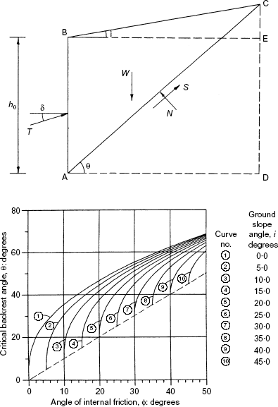
Wedge geometry for active earth pressure condition
Wedge geometry for active earth pressure condition
Values of KA
| Ground slope angle, i | ϕ: degrees | |||||||||
|---|---|---|---|---|---|---|---|---|---|---|
| Degrees | Slope | 5 | 10 | 15 | 20 | 25 | 30 | 35 | 40 | 45 |
| 0 | 0 | 0·735 | 0·604 | 0·504 | 0·423 | 0·355 | 0·296 | 0·244 | 0·199 | 0·160 |
| 5 | 1 : 11·5 | 0·992 | 0·698 | 0·563 | 0·463 | 0·383 | 0·316 | 0·258 | 0·209 | 0·166 |
| 10 | 1 : 5·7 | 0·970 | 0·654 | 0·517 | 0·418 | 0·340 | 0·275 | 0·220 | 0·174 | |
| 15 | 1 : 3·7 | 0·933 | 0·602 | 0·467 | 0·371 | 0·295 | 0·234 | 0·183 | ||
| 20 | 1 : 2·7 | 0·883 | 0·545 | 0·414 | 0·322 | 0·250 | 0·193 | |||
| 25 | 1 : 2·1 | 0·821 | 0·485 | 0·359 | 0·273 | 0·207 | ||||
| 30 | 1 : 1·7 | 0·750 | 0·422 | 0·305 | 0·225 | |||||
| 35 | 1 : 1·4 | 0·671 | 0·359 | 0·251 | ||||||
| 40 | 1 : 1·2 | 0·587 | 0·297 | |||||||
| 45 | 1 : 1·0 | 0·500 | ||||||||
Use of the Newton–Raphson procedure is common for adjusting factor-of-safety and interslice force inclination in an iterative solution scheme of slope stability analysis by the method of slices (e.g. Wright, 1969). This procedure sometimes fails to converge to a solution for slope stability problems where two-variable non-linearity occurs. It would be helpful to know of the authors' experiences with it for their earth pressure problems where only one-variable nonlinearity occurs.
A unified procedure for active and passive earth pressure calculations using the slope stability analysis procedure by the method of slices was presented in Chugh (1995). In this procedure, the engineer selects the sliding surface geometry and inclination of lateral thrust, and the procedure just solves the recursive equations of force and moment equilibrium for each slice between the retaining wall and the ground surface. The earth pressure problem is solved for different sliding surface geometries until a maximum active earth pressure or minimum passive earth pressure value develops, and the location of the interslice force for the slice at the wall–soil interface is taken as the point of application of the lateral thrust. No equilibrium iterations are involved. In contrast, the authors' procedure seeks to satisfy equations (1), (2) and (4) iteratively. The location of the lateral thrust on the wall by the two procedures may not necessarily be the same. It would be helpful if the authors could comment on which of these two procedures would be better—moment equilibrium of each slice or the use of equations (2) and (4) of the paper—for location of the lateral thrust on the wall.
Contrary to the authors' concerns, judicious use of the known earth pressure theories and recommended procedures on engineering projects leads to safe and economical design of earth-retaining structures. There have not been many reported incidents of failures of these structures. If the deformation and strength properties of the backfill materials and the boundary conditions of the problem are known, the earth pressure problem can be studied in greater detail using advanced theoretical analyses.

