

The authors have extended the method proposed by Steedman & Zeng (1990) to calculate the passive resistance in the presence of horizontal and vertical seismic forces.
This discussion aims to
show that the problem, as formulated by the authors, admits an analytical solution
discuss the effective applicability of the proposed method in calculating the passive resistance
discuss the lateral pressure distribution on the thrust plane AB.
ANALYTICAL SOLUTION OF THE PASSIVE THRUST
The authors suggest obtaining the values of the angle α and time t that minimise the thrust Ppe by means of a trial and error procedure. However, the problem can be solved more effectively analytically, as is shown in the following.
The thrust Ppe depends on the angle α of the failure plane BC and the time t.
The minimum value of Ppe can be obtained by the conditions
As concerning the condition in equation (14), if we introduce the angle θ, defined as
the thrust Ppe becomes
which can be rewritten in a form similar to that solved by Mueller-Breslau (1906). Indeed, as in the pseudo-static case (Greco, 2003), making
it assumes the form
This thrust is minimised when the angle α attains the value
which depends on the time t.
The condition expressed by equation (15) gives the time t when the passive thrust is a minimum. Developing that equation, we have
where
with n = 1, 2, 3.…In the interval [0, 2π], equation (23) has two values, one of which is a minimum and the other is a maximum (Fig. 6). Obviously we are interested in the minimum.
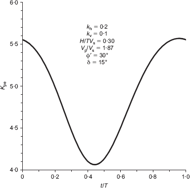
Pseudo-dynamic passive thrust coefficient Kpe in terms of the ratio t/T for a case of practical interest
Pseudo-dynamic passive thrust coefficient Kpe in terms of the ratio t/T for a case of practical interest
Because the time t in equation (23) depends on α, and the angle α in equation (22), depends on t, the values of α and t, minimising the passive resistance, can be obtained by means of an iterative procedure, which can be articulated as follows.
Assume a trial value for α (initially the value related tothe condition θ = 0 can be assumed).
Calculate the coefficients A1, B1, A2 and B2 using equations (24)–(27).
Through equation (23), calculate the time t, corresponding to the minimum, for the current value of α
Calculate the coefficients m1 and m2 using equation (11).
Calculate the angle θ with equation (16).
Calculate angles ϕ′s and δs by means of equations (18) and (19).
If the new value of α is sufficiently close to that assumed in step 1:
then go to step 8;
else assume this value of α for a new iteration by starting from step 2.
Calculate γs with equation (20), and Ppe with equation (21).
End
This iterative procedure converges quickly.
APPLICABILITY OF THE PROPOSED METHOD
In the note presented by the authors, the passive thrust is calculated by using the approach of Coulomb (1773), which presupposes a slip surface BC of planar shape. This hypothesis affects the feasibility of the solution considerably. With regard to this, Fig. 7 reports in graphic form the values of passive thrust coefficients, static (Kp) and pseudo-dynamic (Kpe), in terms of the ratio δ/ϕ′ The continuous lines refer to Coulomb's method (the method proposed by the authors is considered as falling within Coulomb's approach); the broken line is obtained by the method of characteristics (Sokolovski, 1960), a method in which the form of the slip surface is not fixed a priori but obtained as part of the solution. As can be seen, Coulomb's method can confidently be used when the ratio δ/ϕ′ is sufficiently low (generally not over 0·3–0·4). In this case, in fact, the slip surface BC does not differ appreciably from a straight line. For usual values of the ratio δ/ϕ′ (which are frequently in the range between 1/2 and 2/3) the error can became appreciable. This consideration concerns the static passive thrust coefficient Kp, but, because the behaviour of Kpe is very similar to that of Kp, it is probable that an analogous consideration about the ratio δ/ϕ′ is also pertinent to Kpe.
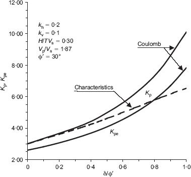
Static (Kp) and pseudo-dynamic (Kpe) passive thrust coefficients in terms of the ratio δ/ϕ′ for a case of practical interest
Static (Kp) and pseudo-dynamic (Kpe) passive thrust coefficients in terms of the ratio δ/ϕ′ for a case of practical interest
Moreover, there is another consideration, which it is interesting to take into axcount. Previously, we transformed the pseudo-dynamic problem into an equivalent static one (and solved it using the solution of Mueller-Breslau), by substituting the angles ϕ′ and δ with the angles ϕ′s and δs respectively.
As is evident in Fig. 8, relative to a specific case, the value of the ratio δs/ϕ′s relative to the value of t minimising Kpe, is considerably higher than the corresponding value of the ratio δ/ϕ′ This seems to suggest the need for a deeper discussion of the question of the applicability of the proposed method, which, however, has the great advantage of a simple formulation and an easy analytical solution.
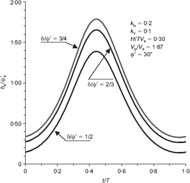
Ratio δs/ϕ′s plotted against the ratio t/T for a case of practical interest
Ratio δs/ϕ′s plotted against the ratio t/T for a case of practical interest
PRESSURE DISTRIBUTION ON THE WALL
A rigorous location of the point of application of the thrust requires the evaluation of the lateral pressure distribution ppe(z). This is generally obtained under the hypothesis that the failure wedge ABC fails internally along planes, starting from the plane AB and inclined at angles α(z) The wedge ABC thus contains subwedges, having a common vertex A and being limited by a local failure plane inclined at α(z).
In the method of Coulomb, as generalised by Mueller-Breslau, and in the pseudo-static method of Mononobe & Okabe, these planes are independent of z (are parallel to one another), because the inclination α does not depend on H, when we analyse the equilibrium of the wedge ABC. Therefore it does not depend on z, when we analyse the equilibrium of a sub-wedge of height z, and develop the analysis by substituting H with z.
As concerning the pseudo-dynamic analysis, we observe that, as emerges from equations (16) to (22), the angle α depends on H (and, consequently, depends on z, when a subwedge z high is considered). In equation (12) of the authors' note, as well as in equation (13) of the paper by Steedman & Zeng (1990), the pressure distribution on the wall is calculated by differentiating the passive resistance Ppe with respect to the depth z, without considering that the angle α is not constant, but varies with z.
However, the analytical differentiation of a(z) is complex, and the function α(z) varies a little with z (generally within 3–4°). Therefore the relationship concerning ppe(z), which must be considered a simplified form, is probably sufficiently approximate for practical applications.
Authors' reply
The authors are grateful to the discusser for showing interest in their work, and for proposing an alternative approach in which the problem can be solved by an equivalent static analytical approach (Mueller-Breslau, 1906; Greco, 2003).
ANALYTICAL SOLUTION OF THE PASSIVE THRUST
The discusser has pointed out that the problem can be solved more effectively analytically by transforming the pseudo-dynamic problem into an equivalent static one and solving it by using the solution of Mueller-Breslau as against the pseudo-dynamic method discussed by the authors in their Technical Note, in which the values of the angle α and time t that minimise the thrust Ppe are obtained by means of a trial and error procedure. But the authors would like to emphasise that an effective optimisation technique using the Excel spreadsheet tool Solver has been applied in the present study to minimise the value of seismic passive earth pressure coefficient (Kpe) with respect to t/T and α
Figures 9 and 10 show the effective use of the optimisation technique used to obtain values of the seismic passive earth pressure coefficients. Again, as compared with the value of seismic passive earth pressure coefficient (Kpe) reported in Fig. 6 using the alternative analytical approach as suggested by the discusser, the value of seismic passive earth pressure coefficient (Kpe) reported in Fig. 9 is a minimum. The discusser has reported the minimum value of Kpe as 4·063 for the dimensionless parameter t/T = 0·44, as shown in Fig. 6. However, the authors have reported the minimum value of Kpe as 3·420 for dimensionless parameter t/T of 0·231 as shown in Fig. 9. Then Kpe is optimised further with respect to failure wedge angle α, which yields the value of Kpe as 3·220 for α = 22·5°, as shown in Fig. 10.
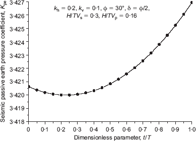
Seismic passive thrust coefficient Kpe in terms of the ratio t/T for a case of practical interest
Seismic passive thrust coefficient Kpe in terms of the ratio t/T for a case of practical interest
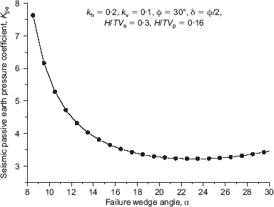
Seismic passive thrust coefficient Kpe in terms of failure wedge angle α for a case of practical interest
Seismic passive thrust coefficient Kpe in terms of failure wedge angle α for a case of practical interest
APPLICABILITY OF THE PROPOSED METHOD
The pseudo-dynamic method of analysis presented in the technical note is an extension to the Mononobe–Okabe method (1926, 1929), which considers the effect of time and phase change in vertically propagating shear and primary waves through the backfill. The Mononobe-Okabe method, is an extension to Coulomb's (1773) method which assumes the planar rupture surface behind the retaining wall. Thus the pseudo-dynamic method discussed here is also based on the assumption of a planar rupture surface. The authors do admit that this hypothesis affects the feasibility of the solution considerably, that the present solution is applicable when the ratio δ/ϕ is sufficiently low, and that for usual values of the ratio d/ϕ′ (which are frequently in the range between 1/2 and 2/3) the error can become appreciable. When δ/ϕ is greater than 1/2 the failure surface becomes curved (Kramer, 1996) and the present pseudo-dynamic method, which supposes a slip surface BC of planar shape, cannot be applied. However, the assumption of a planar rupture surface is made in the present pseudo-dynamic method of analysis to avoid further complicating the problem. The assumption of a planar rupture surface for seismic passive earth pressure has also considered by previous researchers (e.g. Mononobe & Okabe, 1926, 1929—see Kramer, 1996; Davies et al., 1986).
PRESSURE DISTRIBUTION ON THE WALL
The discusser has rightly pointed out that in the method of Coulomb (1773) and in the pseudo-static method of Mononobe & Okabe (1926, 1929), failure planes are independent of z and are parallel to one another, because the inclination α does not depend on H when we analyse the equilibrium of the wedge ABC. Therefore it does not depend on z, when we analyse the equilibrium of a sub-wedge of height z, and develop the analysis by substituting H with z. But again, according to the alternative approach suggested by the author (equations (16) to (22)), it is evident that the angle α depends on H (and, consequently, depends on z, when a subwedge of height z is considered).
The discusser has pointed out that in equation (12) of the authors' note, and equation (13) of the paper by Steedman & Zeng (1990), the pressure distribution on the wall is calculated by differentiating the total passive resistance Ppe with respect to the depth z, without considering that the angle α is not constant, but varies with z.
Again, the discusser has pointed out that the analytical differentiation of α(z) is complex, that the function α(z) varies a little with z (generally within 3°4°), and therefore that the relationship concerning Ppe(z), which must be considered in a simplified form, is probably sufficiently approximate for practical applications.
The authors do not agree with this point raised by the discusser, and have found that, in the pseudo-dynamic method of analysis, the failure wedge angle α is constant and does not vary with the height H of the retaining wall.
The value of the failure wedge angle α is selected so as to get the minimum value of seismic passive earth pressure coefficient (Kpe) and is constant for a given retaining wall of height H.
The authors also would like to point out, in the context of the above discussion, that, because the failure wedge angle α does not vary with the height H of the retaining wall and thus consequently does not vary with z, the pressure distribution on the wall calculated by differentiating the passive resistance Ppe with respect to the depth z will not be affected by variation of the failure wedge angle α (See equation (12) of the technical note, and equation (13) of the paper by Steedman & Zeng (1990)).

