The authors have presented an extremely useful database of punchthrough for spudcans on hard over soft clays. Like many consultants in practice, the discusser must generally make recommendations in a timescale and budget that do not allow for centrifuge tests or LDFE analyses.
Equation (2) of the paper represents SNAME's adaptation (SNAME, 2002) of Brown & Meyerhof's (1969) bearing capacity equation. Dean (2008) observed that the factor of 3 in that equation did not seem to be well justified, and proposed that it be replaced by 4α. The 4 comes from a simple analysis of a cylindrical plug, and α was included as a potentially useful modifying factor. Fig. 14 shows an idealisation that is not very different from the authors' Fig. 7(b), and from which it may be inferred that a further modification is required to account for descent of the soil plug into uniform clay
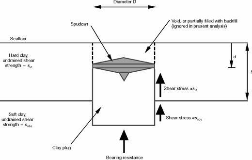
where qb is the bearing capacity of the underlying clay at the base of the plug that has descended distance d, and the same α is assumed for the underlying clay as for the stronger overlying material. The overlying clay layer prevents the underlying clay from achieving a general shear mechanism, so qb might not be the same as for general shear, and is not necessarily affected by a depth factor. Backflow is not considered herein. Dividing the above by the undrained strength of the underlying clay gives
with
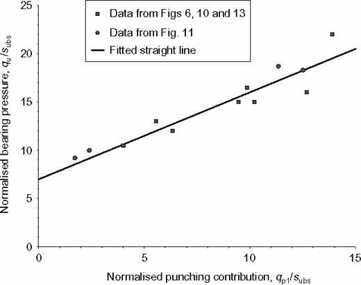
qp1 is the shear resistance on the sides of the cylindrical plug, assuming α = 1. Hence we can measure α by plotting qu/subs against qp1/subs, and we can determine qb/subs from the intercept.
Figure 15 shows such a plot. Table 5 lists the data for clay-over-uniform-clay that have been plotted from the original paper. The figure indicates that the above proposals might be a satisfactory development for SNAME (2002), and that α = 0·9 and (qb − γ′d)/subs = 7 fit the data reasonably well.
Data and calculations
| From original paper | Estimated by discusser from original figure | Calculated using equation (5) | ||||
|---|---|---|---|---|---|---|
| Figure | Test | t/D | subs/sut | d/D | qu/subs | qp1/subs |
| 6,13b | E1UU-II-T5 | 0·75 | 0·64 | 0·3 | 10·5 | 4·01 |
| 6,11a,13a | E2UU-II-T5 | 0·75 | 0·29 | 0·05 | 16·5 | 9·86 |
| 10a,13b | E1UU-II-T6 | 1·5 | 0·75 | 1·25 | 12 | 6·33 |
| 10a,11b | E2UU-II-T6 | 1·5 | 0·51 | 0·6 | 15 | 9·46 |
| 10b | E1UU-IV-T11 | 1·25 | 0·68 | 0·95 | 13 | 5·56 |
| 10b,11a,13a | E2UU-IV-T11 | 1·25 | 0·31 | 0·25 | 22 | 13·90 |
| 10c | E1UU-IV-T12 | 2·5 | 0·73 | 2·35 | 15 | 10·22 |
| 10c,11b | E2UU-IV-T12 | 2·5 | 0·62 | 1·4 | 16 | 12·70 |
| 11a | E2UU-I-T2 | 0·25 | 0·53 | 0·05 | 9·2 | 1·72 |
| 11a | E2UU-III-T8 | 1 | 0·32 | 0·15 | 18·7 | 11·35 |
| 11b | E2UU-I-T3 | 0·5 | 0·75 | 0·2 | 10 | 2·40 |
| 11b | E2UU-III-T9 | 2 | 0·52 | 0·8 | 18·3 | 12·52 |
Note: Test numbers in Fig. 11 of the original paper, and subs/sut ratios for these tests, have been inferred from the data given there and in Table 3 of the original paper.
The authors' comments are sought. Are there any data available that might conflict with the above proposals? Would the straight-line fit be even better if backflow effects had been accounted for? Are there data available that might clarify whether α and qb/subs might depend on the ratio of the strengths of the two clay layers, for example, or other factors such as the ratios of layer thicknesses to spudcan diameter?
Authors' reply
We thank the discusser for his interest in our paper. The discussion focuses on the SNAME (2002) expression for assessing spudcan penetration resistance in stiff-over-soft clays (equation (2) in the original paper), recommending a replacement of the factor 3 in the first term by the theoretical value of 4, together with an adjustment coefficient α, and also replacing the later terms in the expression by the soil plug bearing resistance qb, with appropriate adjustments for the overburden stress. We agree with the discusser that this expression matches data provided in the paper well, as summarised in Table 5 (all for cases where the underlying layer was essentially uniform strength).
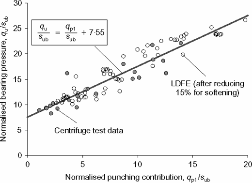
We have supplemented the data in Table 5 with additional data from the paper, and from more recent model tests (Hossain & Randolph, 2010b), and also with results from large-deformation finite-element (LDFE) analyses (Hossain & Randolph, 2009; 2010a) for uniform-over-uniform clay and uniform-over-non-uniform clay (kD/subs > 0). Fig. 16 shows the (qu/sub)p values plotted as a function of normalised punching shear contribution qp1/sub. The results from LDFE analyses were reduced by 15% to account for the effect of softening (Hossain & Randolph, 2009). For kD/subs > 0, the values of sub in the denominator were taken as the operative strength at the base of the plug, and calculated according to , where the last term takes into account the effect of increasing strength. Consistent with the discusser's approach, the height of the plug in the lower layer was taken equal to the penetration depth of the spudcan (d). In calculating qp1 following equation (5), subs was taken as an average value over the height of the plug in the lower layer (sub,avg = subs + 0·5kd). The values show a clear linear trend, but the best fit is provided by taking α = 1 and the last term as 7·55.
A significant problem with this approach is that it is first necessary to estimate the penetration, d, at which the spudcan mobilises peak resistance. Alternatively, different values of d can be assumed, starting from zero, leading to a linear decrease in the bearing resistance, as shown in Fig. 17. In practice, though, field and model test data, and numerical analysis, all show a somewhat different profile of resistance, with the peak resistance generally occurring after significant penetration into the upper layer.
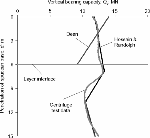
Centrifuge test data against predictions (D = 12 m, t/D = 0·5, sut = 30 kPa, subs = 8·5 kPa)
Centrifuge test data against predictions (D = 12 m, t/D = 0·5, sut = 30 kPa, subs = 8·5 kPa)
Hossain & Randolph (2009) provided a general approach for calculating the complete profile of penetration resistance in two-layered clays. This is shown alongside a typical centrifuge model test profile in Fig. 17. The approach gives expressions to calculate the peak penetration resistance, and the penetration (d/D)p at which it occurs, with the former expressed as
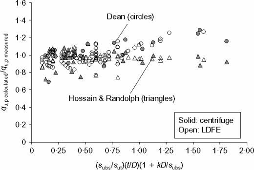
The accuracy of this expression is compared with that proposed by the discusser in Fig. 18, which shows the ratio of calculated qu,pcalculated over measured qu,pmeasured (centrifuge tests and LDFE) with respect to (subs/sut)(t/D)(1+kD/subs). The ratios of calculated to measured resistance lie essentially in the range 0·75 to 1·08 using the above expression, and between 0·75 and 1·25 using the discusser's expression. Either expression is therefore adequate to calculate the peak bearing resistance during penetration, but the need to first estimate the penetration at which this occurs for the discusser's approach is a significant limitation.