
The authors have presented a paper (Kim et al., 2010) for calculating the active thrust on retaining walls in seismic conditions analysed with the pseudo-static method, including a line load and a uniform surcharge on the backfill for a backfill with friction and cohesion.
Following Coulomb's approach, the problem is tackled using the limit equilibrium method, assuming a planar slip surface for limiting the thrust wedge behind the wall. The problem analysed by the authors in this way is an extension of Coulomb's method, which is a very versatile approach, suitable for solving problems with general conditions of geometry and loads. In this approach the thrust connected to a given inclination of the failure plane is obtained from the two equilibrium conditions of forces acting on the thrust wedge. The solution is always found by maximising the thrust with respect to the inclination angle α of the failure plane limiting the thrust wedge. This maximisation can always be done numerically, with a simple computer code. However, an analytical solution is of course more elegant.
Many problems concerning the earth thrust calculated with Coulomb's approach have an analytical solution. Among them may be recalled
(a) the original problem of Coulomb (1776) with β = θ = δ = 0 and that geometrically generalised of Breslau-Müller (1906) with β ≠ 0, θ ≠ 0 and δ ≠ 0
(b) backfill subjected to a uniform surcharge (Das, 1987), or a distanced uniform surcharge (Motta, 1994), or lines or a strip of vertical surcharge (Greco, 2006a, 2006b)
(c) seismic forces with the pseudo-static approach (Arango, 1969; Greco, 2003)
(d) backfill partially submerged in a static groundwater (Greco, 2006c)
(e) backfill soil with friction and cohesion (Greco, 2010).
As can be seen, these problems have distinct analytical solutions, but none is similar to the generalised method of the authors. However, a simple analytical solution is possible in this case too, and the present discussion will show how to obtain it.
With reference to Fig. 6(a) (having the same notation as the authors), where x is the horizontal distance of point C from point A
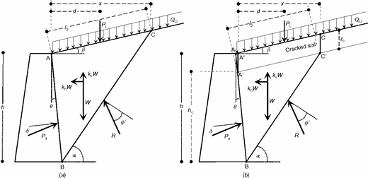
Forces acting on the thrust wedge: (a) soil resistant to traction; (b) soil unresistant to traction and cracked up to depth zc
Forces acting on the thrust wedge: (a) soil resistant to traction; (b) soil unresistant to traction and cracked up to depth zc
Therefore, equation (6) of the authors can be rewritten as
where
The maximum value of the thrust Pa is obtained from the condition
which gives a quadratic equation
where
The solution is given by the positive root of equation (18). Once the distance x is obtained, it is necessary to check that x is greater than d. If so, the thrust Pa is calculated through equation (12). If not, because PL does not act on the thrust wedge, the coefficients a0 and a1 must be recalculated with the condition PL = 0 and then the new coefficients C calculated in equation (19c).
The analysis of the authors does not consider the presence of tension cracks. Because the stress methods (Rankine, 1857; Sokolovsky, 1965) show that the upper zone of the backfill is subjected to traction, this presupposes that the soil is capable of sustaining such a type of stress.
If it is assumed that the soil is unable to support tractions, the presence of tension cracks on the topographical profile of the backfill must be admitted. Therefore, the analysis of the authors should be modified by considering that the upper part of the backfill up to a depth zc is cracked and acting as a uniform surcharge on the effective thrust wedge (Fig. 6(b)). However, as can be seen, neglecting the weight of the triangle AA′A″, the analytical solution illustrated above can also be used in this case, by substituting h by hc and QU by QZ in equations (10)–(13), (15) and (19), where
