

The discusser read with interest the paper by Diakoumi & Powrie (2013) proposing an interesting method for the analysis of propped flexible retaining walls based on the mobilisation of active and passive pressures on the wall due to movement of wall segments. An assumed deformation mechanism within the soil is used to estimate the strain associated with rotation of a particular wall segment. This mechanism is then superposed for each wall segment, the resulting earth pressures are calculated; the equality between the wall bending moments implied by equilibrium and those required to achieve the appropriate bending of the wall is used to calculate the rotation of each segment. Although the method of analysis provides insight into the conservatism of conventional design calculations for different wall flexibilities, there are two aspects of the paper which provoke further discussion.
ADMISSIBLE DISPLACEMENT FIELD
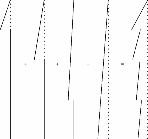
Use of the mobilisable strength design (MSD) procedure as described by Osman & Bolton (2005), Klar & Osman (2008) and by the authors requires the assumption of a kinematically admissible displacement field. The displacement field used by the authors is that described by Bolton & Powrie (1988) for the rotation of a bulkhead about its top. Although this mechanism is appropriate for a rigid propped retaining wall, the superposition of four of these mechanisms to model an articulated wall (as a simplification of a flexible wall) does not appear appropriate. It can be seen from Fig. 17 that the superposition of these four mechanisms would imply a discontinuous wall shape, with the wall shearing at each ‘hinge', rather than merely bending as would be desired.
STRAIN CALCULATION
The four displacement fields superposed in the analysis each generate strains in regions of soil that may or may not overlap, causing calculation of a strain associated with each wall segment to be problematic. The authors state that this superposition
…is not a superposition of shear strains within a given physical zone of soil, but the summation of the shear strains associated with the rotation of a given section of the wall which could occur in different and non-overlapping zones of soil.
The discusser cannot see how this type of superposition gives an appropriate calculation of the strain and hence earth pressure associated with a particular wall segment. If half of a soil body experiences 1% strain and then the other half experiences 1% strain, the strain in the soil body is 1%, not 2%. Equally, a change in the assumed order of rotation of the wall sections changes the analysis, despite an identical final wall configuration.
PROPOSED AMENDMENTS TO METHOD
In order to address these concerns, a modified displacement field could be developed based on the displacement field for rotation about the wall base proposed by Bolton & Powrie (1988). Superposition of two of these mechanisms allows a mechanism to be developed for a hinged wall movement, as illustrated in Fig. 18. A rotation about the wall top, superposed with three of these mechanisms for articulation of the three hinges, allows a global mechanism to be developed, which could be used in the procedure described by the authors.
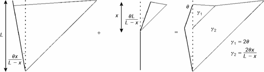
This amendment addresses both concerns raised above; it provides a deformation mechanism within which the wall remains continuous and also allows by superposition calculation of the strains in each of eight non-overlapping zones of soil, as shown in Fig. 19. The resulting strains being
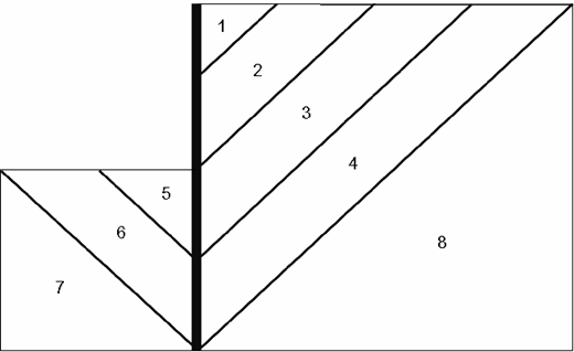
These strains could then more appropriately be related to the earth pressures acting in different soil zones and hence on different sections of the wall.
Authors' reply
The authors are grateful to Dr Haigh for his interest in their work and his thoughtful discussion. The mechanism proposed in the original paper is used to calculate the maximum strain associated with each wall segment. The strains within an individual physical zone of soil are not superimposed in the conventional sense; rather, the shear strains associated with the rotation of a given section of the wall, which could occur in different and possibly non-overlapping zones of soil, are summated. The authors accept that this approach is unusual, but conventional superposition is inappropriate, for the reasons identified by Dr Haigh in his discussion.
The authors confirm that there is a discontinuity in the displacement of each zone as indicated in Fig. 17, but in their calculation the wall rotations are determined on the basis that the wall is assumed to be continuous. This is clarified in the definition sketch given in Fig. 20 and the associated equations (68) to (75). The authors apologise that this was not clearer in the original paper; this was perhaps a result of the desire during the review process to limit the amount of what was perceived to be previously published material. Full details are given in Diakoumi (2007). As the number of soil zones is increased, the discrepancy associated with this approximation would decrease.
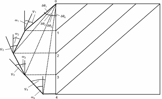
Calculation of wall hinge rotations ψ: continuous wall with discontinuous soil displacements
Calculation of wall hinge rotations ψ: continuous wall with discontinuous soil displacements
Figure 17 indicates two deflections of different magnitude at each wall hinge, each of which is associated with the strains of different magnitude developed in non-conflicting soil triangles behind (or in front of) the wall. In their paper, the authors have only considered the strain associated with the larger of the deflections within each of the soil triangles. This is consistent with the approach presented by Bolton & Powrie (1988) for a rigid embedded wall rotating about its crest. As shown in figure 11 of Bolton & Powrie (1988), in the case of the two non-conflicting soil triangles in front of the wall, which have different magnitudes of strain and different deflections at the top and bottom, only the larger of the deflections is used to calculate the strain. Bolton & Powrie (1988, p. 175) state that ‘if the objective is solely to extract a reasonable value for the ratio between mobilized shear strain and wall rotation, the larger of the two strains should suffice.'
Dr Haigh's displacement mechanism is elegant, but may not be an advance on the approach that the authors propose. The shear strain in his zone 1 is associated with lateral compression; that is, the earth pressure coefficient there would tend towards passive rather than active. (It is possible that this might be the case in zones 2 and 3 as well.) Thus the mechanism may not be as easy to implement as it might at first sight appear.
There are other possible approaches, but all of those the authors have so far investigated in detail involve some degree of inconsistency. The mechanism presented in the paper involves an element of approximation, but is at least self-consistent.

