


The maximum shear modulus (G0(ij)) of rooted soils is crucial for assessing the deformation and liquefaction potential of vegetated infrastructures under seismic loading conditions. However, no data or theory are available to account for the anisotropy of G0(ij) of rooted soils. This study presents a new model that can predict G0(ij) anisotropy of rooted soils by incorporating the projection of the stress tensor on two independent tensors that describe the soil fabric and root network. Bender element tests were conducted on bare and vegetated specimens under isotropic and anisotropic loading conditions. The presence of roots in the soil increased G0(VH) at all confining pressures (p′), as well as G0(HH) and G0(HV) at low p′. However, the trend was reversed at higher p′ because the roots reduced the effects of confinement on G0(ij) by replacing stronger soil–soil interfaces with weaker soil–root interfaces. Roots made the soil fabric and G0(ij) more anisotropic. The proposed model can effectively predict the observed anisotropy of G0(ij) under isotropic and anisotropic loading conditions. The new model also offers a new method for determining the fabric anisotropy of sand based on the anisotropy of shear modulus.
INTRODUCTION
Plant roots reinforce soil and increase its shear strength by mobilising the tensile and/or flexural properties of the roots and the soil–root interfacial shear properties (Stokes et al., 2014; Leung et al., 2019; Wu et al., 2021; Karimzadeh et al., 2024). Recent studies have demonstrated that plant roots can effectively resist cyclic loading (Wu et al., 2023) and enhance the resistance of the soil against liquefaction (Karimzadeh et al., 2021, 2022). Indeed, centrifuge modelling works reported by Liang (2017, 2020) found that roots can reduce the settlement of a slope crest against seismic loading. Wang et al. (2018) also used centrifuge modelling to show that the presence of roots can enhance the resistance of pipeline uplift induced by liquefaction. Determining the maximum shear modulus G0(ij) of rooted soils is crucial in understanding the dynamic root–soil interaction, given that it plays a vital role in predicting ground deformation and assessing the liquefaction potential under seismic loading conditions (e.g. Ng et al., 2004; Liu & Mitchell, 2006). The G0(ij) of rooted soils can be highly anisotropic due to not only the intrinsic soil fabric but also the root network (Karimzadeh et al., 2024), collectively referred to as inherent anisotropy. Fabric evolution due to straining of soils under different loading conditions and stress states could also contribute to G0(ij) anisotropy, known as induced anisotropy (Li & Dafalias, 2002, 2012; Li & Li, 2009). Thus, measuring and modelling G0(ij) and its anisotropy of rooted soils are needed to provide a more informed design against the safety and serviceability of vegetated infrastructures.
To the best of the authors’ knowledge, no published study has focused on the behaviour of G0(ij) of rooted soils. However, the G0(ij) of fibre-reinforced soils, which might share some similarities with rooted soils, has been investigated (e.g. Choo et al., 2017; Li and Senetakis, 2017). In general, these studies have reported that the inclusion of fibres in soils reduced G0 in the vertical–horizontal plane (G0(VH)), especially when the shear wave propagates vertically along the vertical axis of the soil specimen with horizontal polarisation (i.e. the direction of particle motion). Li et al. (2022) showed that fibres increased the anisotropy of G0(ij) under isotropic and anisotropic loading conditions. They also demonstrated that fibre distribution in the soil significantly influenced G0(ij). An increase in the fibre content caused a rise in G0(HH) but a decrease in G0(VH) and G0(HV), probably because the majority of fibres were oriented horizontally, aligning with the soil bedding plane due to compaction. Adding fibres to the soils would replace the stronger particle–particle contacts with the weaker particle–root–particle contacts. The weaker contacts would become more significant in the vertical direction compared to the horizontal direction due to the fibre distribution in the soil, leading to a reduction in the values of G0(VH) and G0(HV) (Li et al., 2022). Although fibre-reinforced soil and rooted soil share some similarities in terms of the tensile strength mobilisation in fibres or roots (e.g. Diambra et al., 2010; Gao & Zhao, 2013; Karimzadeh et al., 2024), they have some fundamental differences: (a) the distribution and orientation between roots and fibres in the soil (e.g. Michalowski & Čermák, 2002; Karimzadeh et al., 2024); (b) fabric of the host soil induced by different sample preparation methods (Karimzadeh et al., 2021, 2022); and (c) the mechanical properties of fibres and roots (e.g. Correia et al., 2021; Wu et al., 2021, 2023). Thus, existing findings and understandings of G0(ij) anisotropy derived from fibre-reinforced soils cannot be directly transferred to explain the behaviour of rooted soils. Additional fundamental research on the effect of the root network developed in soil on the G0 anisotropy of rooted soils is needed.
Based on observations from a vast amount of published experimental datasets for bare soils, two key considerations have been noted: (a) G0(ij) has been considered to be a function of only two normal effective stress components within the shear plane (i.e. in the direction of the shear wave propagation and polarisation) yet independent from the out-of-plane effective stress component (e.g. Roesler, 1979; Wang & Mok, 2008; He et al., 2022); and (b) the two stress components contribute to G0 equally (e.g. Fioravante et al., 1998; Wang & Mok, 2008). Following these considerations and the work by Hardin & Black (1968), the following semi-empirical equation for G0(ij) at various shear wave propagation planes has been commonly used in the literature (e.g. Jamiolkowski et al., 1995; Ng & Leung, 2007):
where i is a subscript that refers to the direction of wave propagation, which can be in the horizontal direction (H) and the vertical direction (V); and j is the other subscript that indicates the direction of wave polarisation; C(ij) is an inherent material constant (which has the same unit as velocity) in the ij plane, and it depends on various factors such as the particle size, particle shape, particle arrangement (or packing) and any particle bonding (Ng & Yung, 2008); pr is a reference pressure with a typical value of 1 kPa; σii and σjj are the normal components of the stress tensor in the shear wave propagation direction and particle polarisation, respectively; and F(e) is a function relating G0(ij) to void ratio e.
The relative orientation between the loading direction and material fabric, regardless of the type of anisotropy (i.e. inherent and induced), determines the degree of anisotropy in G0(ij) (Pietruszczak & Mroz, 2000; Nguyen et al., 2018). Thus, using C(ij), or its equivalent, which is independent of stress path, in other theories is inadequate to address the anisotropy of G0(ij) without incorporating the effects of stress or strain orientation. No theory has been developed to reconcile this problem. Further modification is needed to explain the anisotropic behaviour of G0(ij) under the isotropic and anisotropic consolidation conditions for soils with and without plant roots.
The aim of this study is to derive a new formulation for capturing the anisotropy of G0(ij) of bare and rooted soils under general three-dimensional (3D) isotropic and anisotropic loading conditions. The formulation employed two independent fabric tensors to describe the internal structure of the host soil and the root system. Triaxial bender element tests were conducted to measure the variation in G0(ij) of bare and rooted soils of varying root contents under isotropic and anisotropic loading conditions, following compression and extension stress paths, for validating the new model. The new G0(ij) anisotropy formulation was validated against the data obtained from isotropic loading conditions, and the predictability of the model for the data obtained from anisotropic loading conditions was also evaluated.
THEORETICAL BACKGROUND
In this study, equation (1) was used as a reference model to derive a new equation for describing the anisotropy of G0(ij) in rooted soils. Two new modifications were introduced. The first one involved incorporating the effects of unloading (i.e. loading history) on G0(ij) (Ni, 1987; Ku & Mayne, 2013). The second modification aimed to capture the degree of anisotropy by replacing the constant C(ij) with a new stress-dependent dimensionless anisotropic state variable A(ij). The new equation is:
where vr is a reference velocity, which is taken as 1 m/s to ensure consistent dimensions on both sides of the equation; pr is a reference pressure taken as 1 kPa; F(e) is the void ratio function, expressed as F(e) = (2·17 − e)2/(1 + e) for round-grained sands with e < 0·8 following Hardin & Richart (1963); ρ is the density of the soil; and R0 is the isotropic overconsolidation ratio (p′max/p′), where p′ is the current mean effective stress upon isotropic or anisotropic loading or unloading conditions and p′max is the historically maximum value. These fabric tensors define the state variable that can characterise the orientation and intensity of inherent and induced material anisotropy micromechanically (Tobita, 1988; Pietruszczak & Mroz, 2000; Li & Dafalias, 2002, 2012; Li & Li, 2009). Notably, the fabric evolution due to straining (i.e. induced anisotropy) was ignored in the present study, given the rather low deviatoric strain levels experienced by the soil specimens in the triaxial test programme. The fabric tensor of bare soil can be expressed as (Pietruszczak & Mroz, 2000)
where F1, F2 and F3 are the principal values of Fij; η0|B = (F1 + F2 + F3)/3 is the mean of the principal values, which indicates the average of material properties in three different directions; and Ω1|B, Ω2|B and Ω3|B are the principal values of the deviatoric part of the tensor. For rooted soils, an additional fabric tensor for the root network () needs to be defined to capture the anisotropy arising from root morphology, orientation, surface area and their combinations (Karimzadeh et al., 2024).
where η0|R is the mean of the principal values of ; and Ω1|R, Ω2|R and Ω3|R are the principal values of the deviatoric part of the root network tensor. The two fabric tensors (equations (3) and (4)) provide a mathematical definition of the fabric characteristics of a rooted soil, which are independent of stress conditions. According to the representation theory of tensors (Wang, 1970), anisotropic state variables, which include the joint invariants and invariants of stress (or strain) and fabric tensors, should be used in constitutive modelling of anisotropic soil behaviour.
The traction of the loading moduli on the planes that are normal to the axes of fabric in 3D space can be defined as follows (Pietruszczak & Mroz, 2000):
where tj is the traction of loading moduli, and e(j)i are the unit vectors representing the principal directions of the fabric tensor. The magnitude of tj can be expressed as
To describe the relative orientation between the loading direction and material fabric, a universal unit loading vector li is introduced as follows:
where Li is a universal loading vector. Previous studies have experimentally demonstrated that the value of G0(ij) is primarily influenced by the normal stress components within the shear wave propagation plane. In the meantime, the out-of-plane normal stress component has little effect (e.g. Roesler, 1979; Wang & Mok, 2008) because it was found to insignificantly alter the distribution and magnitude of the contact normal forces (Wang & Mok, 2008). Consequently, when calculating the loading direction and A(ij), all the out-of-plane stress components were set to 0. Accordingly, the traction of the loading moduli on the planes that are normal to the axes of fabric and loading direction on the various wave propagation planes (1, 2 or 1, 3 or 2, 3) can be calculated by the following equations (Fig. 1):
where Λ(j)i is the generalised loading direction along the plane of shear wave propagation. Correspondingly, the united loading moduli (λ(j)i) can be calculated by the following equation:
The projection of on λ(j)i, which uses the quadratic form of by combining various invariants and joint invariants of fabric and stress tensors, has been used by Pietruszczak & Mroz (2000). However, using this approach to model the anisotropy of G0(ij) requires additional consideration of the physics of shear wave propagation. The shear wave velocity propagation in the soil is primarily related to the effective stress in the normal direction of the soil fabric (i.e. soil particle contacts). In other words, an increase in the contact normal forces on the shearing plane would cause a rise in the shear modulus (Wang & Mok, 2008). This phenomenon means that a loading direction that has a lower projection value on would have more contribution to the increase in effective stress in the normal direction of the fabric axes. Therefore, projecting the traction of loading on for a given direction cannot accurately represent the effect of normal stress because the projection of on λ(j)i primarily determines the shear stress along the fabric axes of soil. Thus, a new form of loading direction (n(j)i), which is perpendicular to the general loading direction (Fig. 1), was defined to model the effect of normal stress on wave propagation:
Notably, the absolute values of uji and uij are given here because the two vectors perpendicular to λ(j)i in the ij plane. As will be shown later, only the absolute values of uji and uij are important for the stiffness model. Thus, A(ij) can be determined based on the projection of on n(j)i (Pietruszczak & Mroz, 2000). This variable can be obtained using the quadratic form of for 3D loading conditions:
where (n(j)i)T is the transpose of the n(j)i. A(ij) is a homogeneous function of stress with a zero degree. Thus, it would not be affected by the magnitude of stress (Pietruszczak, 2010). When the principal axes of the stress tensor and fabric tensor are the same (i.e. true triaxial test conditions), the following equations in various shear wave propagation planes are derived based on equation (14):
Karimzadeh et al. (2024) suggested that for rooted soils, A(ij) can be decomposed into the anisotropy arising from the soil fabric and root network. Accordingly, A(ij) of rooted soils that follow true triaxial stress paths can be expressed as follows:
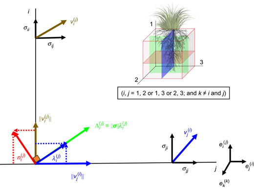
Schematic diagram showing unit tractions of loading moduli on planes that are normal to the axes of the microstructure fabric of the soil and the loading direction on various planes of wave propagation. Notably, this study ignores the minimal effects of out-of-plane stress components on wave propagation on loading traction
Schematic diagram showing unit tractions of loading moduli on planes that are normal to the axes of the microstructure fabric of the soil and the loading direction on various planes of wave propagation. Notably, this study ignores the minimal effects of out-of-plane stress components on wave propagation on loading traction
TEST PROGRAMME
Sample preparation
Triaxial tests were conducted to calibrate and verify the proposed anisotropic model for G0(ij). In this test programme, completely decomposed granite obtained from a construction site in Hong Kong was used, and it was categorised as silty sand according to the Unified Soil Classification System (ASTM D2487 (ASTM, 2018)). Table 1 summarises some relevant soil index properties. The soil was sieved to a particle size smaller than 2 mm before sample preparation. The sieved soil was then oven-dried and mixed with de-aired water until an optimum water content of 12·6% by mass was reached. The moist soil was then sealed and placed in a temperature-controlled room for 12 h to allow for moisture equalisation. The triaxial specimens (each with a diameter of 76 mm and a height of 200 mm) were produced by the static under-compaction method in ten layers, following Ladd (1977). The target initial dry density was 1488 kg/m3, which corresponds to 80% of the maximum dry density. Vetiver (Chrysopogon zizanioides L.), which is a fast-growing, deep-rooted grass species that is considered favourable for shallow slope stabilisation (Stokes et al., 2014; Wu et al., 2021), was chosen for testing. Five tillers of vetiver grass were transplanted to each triaxial specimen. The vegetated specimens were irrigated daily for the first 3 months after transplantation. Subsequently, the irrigation frequency was reduced to twice a week. After a growth period of 12 months, the vegetated specimens were collected for testing (Fig. 2).
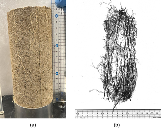
(a) A vegetated specimen (test ID: ISR) placed on the triaxial pedestal; (b) a scanned image of the vetiver roots from the vegetated specimen
(a) A vegetated specimen (test ID: ISR) placed on the triaxial pedestal; (b) a scanned image of the vetiver roots from the vegetated specimen
Index test results of test soil (after Karimzadeh et al., 2022, 2024)
| Index properties | Value |
|---|---|
| Standard Proctor compaction test | |
| Maximum dry density: kg/m3 | 1860 |
| Optimum water content: % | 12·6 |
| Particle-size distribution | |
| Gravel (>4·75 mm) | 0 |
| Coarse sand (4·75–2 mm) | 0 |
| Medium sand (0·425–2 mm) | 50·67 |
| Fine sand (0·063–0·425 mm) | 18·73 |
| Silt (0·063–0·002 mm) | 23·49 |
| Clay (<0·002 mm) | 6·7 |
| D10: mm | 0·002 |
| D30: mm | 0·06 |
| D50: mm | 0·43 |
| Coefficient of uniformity (Cu) | 309·1 |
| Coefficient of curvature (CC) | 2·4 |
| Liquid limit: % | 27 |
| Plastic limit: % | 24 |
| Plasticity index: % | 3 |
| Specific gravity | 2·6 |
| USCS | Silty sand (SM) |
Test plan and procedures
Two series of triaxial bender element tests were conducted to measure the effects of roots on the anisotropy of G0(ij) under isotropic and anisotropic loading conditions. A pair of bender elements was affixed to the top and end platens of the triaxial apparatus to measure the velocities of shear waves propagating in two orthogonal planes of polarisations at different loading steps. In the meantime, another two pairs were mounted at mid-height of each specimen. The samples had a diameter of 76 mm and a height of approximately 160 mm (Fig. 2(b)). This arrangement allowed for the measurements of the shear wave velocities at different planes (vVH, vHH and vHV) to investigate the anisotropy of G0(ij) of bare soil and vegetated specimens with various root volume ratios (RVR; defined as the ratio of total root volume to the total specimen volume; Table 2). The specific gravity of roots was determined by measuring the weight and volume of dry roots exhumed from the samples after tests. The roots were dried for 48 h in the laboratory and then weighed. The roots were then scanned using an Epson scanner (model STD4800; Fig. 2(b)), and the images were analysed by Pro-WinRHIZO software to determine the root volume. After installing in the triaxial apparatus, each specimen was saturated by circulating carbon dioxide (CO2) and de-aired water at a small effective confining pressure of 10 kPa to maintain the stability of specimens during saturation. Subsequently, a back-pressure of at least 80 kPa was applied to the specimens to ensure that the Skempton's b value was always higher than 0·98 before triaxial testing. Fig. 3 shows the stress paths of the two test series. In the first series, four bare and four vegetated specimens were isotropically loaded and unloaded to different effective confining pressures (p′; i.e. 15, 25, 50, 100, 200, 300 and 400 kPa) in steps.
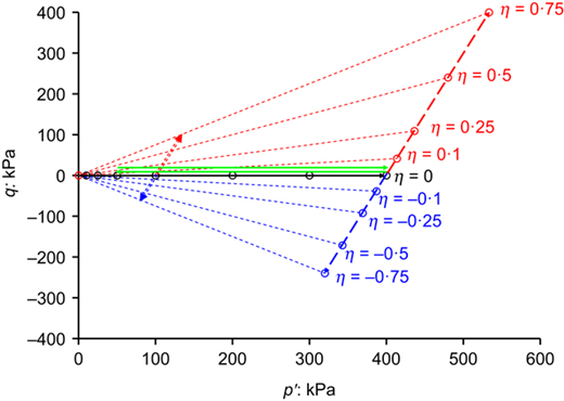
Summary of stress path for measuring shear wave velocity along isotropic loading (solid arrows) and anisotropic loading paths (dashed arrows) at two initial confining pressures of 100 and 400 kPa
Summary of stress path for measuring shear wave velocity along isotropic loading (solid arrows) and anisotropic loading paths (dashed arrows) at two initial confining pressures of 100 and 400 kPa
Summary of test programme
| Test ID | No. of tests | ein* | RVR: % | Stress path | p′ | η | OCRs |
|---|---|---|---|---|---|---|---|
| ISB | 4 | 0·757 −0·800 | 0 | Isotropic | 15, 25, 50, 100, 200, 300, 400 | 0 | 1, 1·33, 2, 4, 8 |
| ISR | 4 | 0·750–0·771 | 0·25–0·47 | Isotropic | 15, 25, 50, 100, 200, 300, 400 | 0 | 1, 1·33, 2, 4, 8 |
| AnB-100C | 1 | 0·797 | 0 | Compression | 100 | 0 to 0·75 | 1 |
| AnB-100E | 1 | 0·794 | 0 | Extension | 100 | 0 to −0·75 | 1 |
| AnR-100C | 1 | 0·720 | 0·62 | Compression | 100 | 0 to 0·75 | 1 |
| AnB-400C | 1 | 0·800 | 0 | Compression | 400 | 0 to 0·75 | 1 |
| AnB-400E | 1 | 0·797 | 0 | Extension | 400 | 0 to −0·75 | 1 |
| AnR-400C | 1 | 0·750 | 0·38 | Compression | 400 | 0 to 0·75 | 1 |
| AnR-400E | 1 | 0·771 | 0·28 | Extension | 400 | 0 to −0·75 | 1 |
*Initial void ratio after placing the specimens on the triaxial apparatus.
This stress history resulted in the specimens having overconsolidation ratios (OCRs) of 1, 1·33, 2, 4 and 8. At each loading step, the shear wave velocities at different planes were measured based on the determination of the arrival time of the shear wave in the specimen between each pair of benders. The transmitted and received signals of the wave were captured using an HP 3563A system oscilloscope. The peak-to-peak method between the transmitted and received wave was used to determine the arrival time of the shear waves, following ASTM (2019). Three excitation frequencies, namely, 5, 8 and 10 kHz, were considered.
Figure 4 shows an example of the transmitted and received wave propagated in the VH plane in a bare and vegetated specimen at p′ of 200 kPa. Evidently, increasing the excitation frequency distorted the wave shape, which made the wave interpretation difficult. Thus, the frequency of 5 kHz was used throughout the test programme for fair comparison of the test results among the various specimens. In the second test series, four bare and three vegetated specimens were first isotropically loaded to a p′ of 100 or 400 kPa. Then, they were anisotropically loaded to different stress ratios (η; ranging between 0 and 0·75 and between 0 and −0·75), in steps, along the compression and extension paths. Similarly, in each loading step, the shear wave velocities were measured following the same procedures as mentioned above. Table 2 summarises the test plan of the two test series.
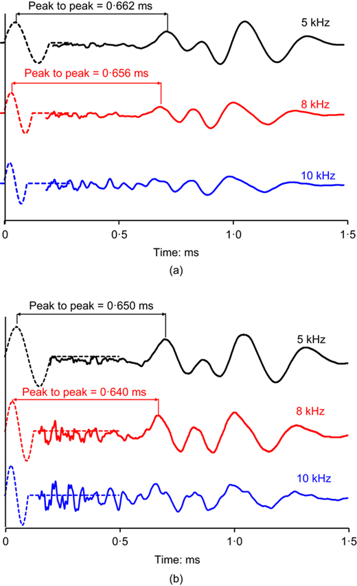
Method of determining arrival time of shear waves at frequencies of 5, 8 and 10 kHz at p′ of 200 kPa for (a) bare specimen; (b) vegetated specimen
Method of determining arrival time of shear waves at frequencies of 5, 8 and 10 kHz at p′ of 200 kPa for (a) bare specimen; (b) vegetated specimen
TEST RESULTS
Figure 5 compares the isotropic consolidation lines (ICLs) and isotropic unloading lines (IULs) between the bare and rooted soils. Notably, the void ratio of the vegetated specimens was calculated by treating the roots as a solid phase. The compressibility index of the rooted soils (λr = 0·075) was lower than that of the bare soil (λb = 0·093), which indicates that the presence of roots made the soil less compressible as the roots occupied some voids to resist against the isotropic consolidation. This phenomenon aligns with the so-called ‘stolen void ratio’ theory hypothesised by Muir Wood et al. (2016) for the case of fibre-reinforced soil; during compression, the roots might have prevented the soil particles from using the voids being ‘stolen’ by them, which makes the rooted soils less compressible than the bare counterpart. Upon unloading, the swelling index of the rooted soil (κr = 0·006) is noticeably lower than that of the bare soil (κb = 0·009), which indicates that the presence of roots made the soil deformation less recoverable. During unloading and soil volume expansion, some tensile strains would be developed in the vegetated specimens to mobilise the tensile stress of the roots (Karimzadeh et al., 2024). The stress transfer from the soil to the roots suppresses the volume expansion and reduces the amount of swelling when compared with the bare soil.
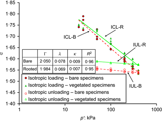
Isotropic consolidation lines (ICLs) and isotropic unloading lines (IULs) of the bare and vegetated specimens. Notably, Γ, λ and κ denote the intercept of the ICLs at p′ of 1 kPa, the gradient of ICLs and the gradient of the IULs, respectively
Isotropic consolidation lines (ICLs) and isotropic unloading lines (IULs) of the bare and vegetated specimens. Notably, Γ, λ and κ denote the intercept of the ICLs at p′ of 1 kPa, the gradient of ICLs and the gradient of the IULs, respectively
Figures 6(a), 6(b) and 6(c) show the variations in G0(VH), G0(HH) and G0(HV) of the bare and vegetated specimens with p′ following isotropic loading and unloading cycles (i.e. from the first test series), respectively. At any given p′, the values of G0(VH) of the rooted soils were generally higher than those of the bare soil (Fig. 6(a)), which can be attributed to two primary reasons: (a) the presence of roots altered the soil fabric in the vertical plane as the majority of roots were oriented vertically; and (b) roots entangled the soil particles, which caused an apparent increase in the effective stress (Karimzadeh et al., 2024) and thus stiffness. Previous studies on fibre-reinforced soils have shown that, in contrast, the presence of fibre could remarkably reduce the G0(VH) of soil because of the alteration of the inter-particle coordination or packing density (Choo et al., 2017; Li & Senetakis, 2017; Li et al., 2019). Unlike the distribution of root orientations, the fibres present in the soil were primarily oriented horizontally because of the use of moist tamping as the sample preparation method (e.g. Michalowski & Čermák, 2002; Diambra et al., 2010; Gao & Zhao, 2013). Thus, the effect of fibres on the soil fabric would be less pronounced in the VH plane, which resulted in a reduction in G0(VH). By contrast, in the horizontal plane, the vegetated specimens had higher values of G0(HV) and G0(HH) than the bare specimen at a relatively low p′ (<100 kPa), but the trend was reversed at the higher p′ of 400 kPa (Figs 6(b) and 6(c)). This phenomenon suggests that the effects of roots on G0(ij) in the horizontal plane was stress dependent, which is consistent with what has been generally found in the case of fibre-reinforced soils (e.g. Li et al., 2019, 2022). At relatively high p′, the effects of the normal and tangential inter-particle contact forces on G0(ij) in the bare specimens should be more pronounced than those of the vegetated specimens. The reason is that the stronger interactions between soil particles that occurred in the bare case have been partially replaced by the weaker particle–root–particle interactions in the vegetated specimens (Fakih et al., 2019; Karimzadeh et al., 2022; Chen & Martinez, 2023).

Variations in (a) G0(VH); (b) G0(HH); and (c) G0(HV) of the bare and vegetated specimens under an isotropic loading–unloading cycle
Variations in (a) G0(VH); (b) G0(HH); and (c) G0(HV) of the bare and vegetated specimens under an isotropic loading–unloading cycle
Evidently, the void ratio of the vegetated specimens was higher than that of the bare specimens at any values of p′ larger than 25 kPa (Fig. 5), which suggests that the presence of roots caused an increase in the void ratio during isotropic consolidation and should have caused a reduction in G0(ij). Therefore, the substantial increases in the G0(ij) of the vegetated specimens in the VH plane across all the values of p′ and those in the HH and HV planes at lower values of p′ (i.e. <100 kPa) were predominantly associated with the effect of roots on the change in soil fabric. Despite variations in RVR among the vegetated specimens (i.e. 0·25% to 0·47%; Table 1), the measured differences in the values of G0(ij), irrespective of the plane of wave propagation, were marginally close to one another. Moreover, the values of G0(ij) along the unloading path were higher than those along the loading one in the bare and vegetated specimens in all the wave propagation planes. This phenomenon is consistent with findings from previous studies that reported the value of G0(ij) in overconsolidated (bare) samples was higher than that of normally consolidated samples (e.g. Viggiani & Atkinson, 1995; Rampello et al., 1997; Vardanega & Bolton, 2013) because of (a) the lower void ratio and (b) the possible change in soil fabric as the soil was overconsolidated (e.g. Houlsby et al., 2005; Rollo & Amorosi, 2022). Indeed, this phenomenon has been accounted for in an existing constitutive modelling framework referred to as elastoplastic coupling, which involves a permanent modification of the elastic stiffness based on changes in the internal microstructure (e.g. Rollo & Amorosi, 2022).
Figure 7 shows the variation in G0(HH)/G0(VH) and G0(VH)/G0(HV) with p′ under the isotropic loading condition for the bare and vegetated specimens. For the bare case, each of the ratios remained practically constant at any given p′, consistent with the findings reported by previous researchers for a similar type of silty sandy soil (Ng & Yung, 2008). The same trend was found for the vegetated specimens. These observations suggest that the fabric in the bare and vegetated specimens did not evolve under isotropic loading conditions, supporting the assumption of non-evolution of fabric in the proposed model. Indeed, under isotropic loading conditions, wherein the projection of loading on the fabric's principal axes remains constant in all directions (i.e. ), a non-constant ratio of G0(ij)/G0(ij) at various p′ values implies the evolution of the soil and root network fabric ( and ) based on equations (15) and (16).
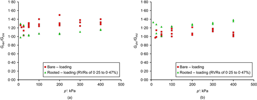
Variation in G0(ij)/G0(ij) with p′ of the bare and vegetated specimens under isotropic loading condition: (a) G0(HH)/G0(VH); (b) and G0(VH)/G0(HV)
Variation in G0(ij)/G0(ij) with p′ of the bare and vegetated specimens under isotropic loading condition: (a) G0(HH)/G0(VH); (b) and G0(VH)/G0(HV)
PARAMETER DETERMINATION FOR THE PROPOSED MODEL
The parameters for the proposed model include n, m and fabric tensors for the bare soil and root network . The parameters n and m can be directly determined based on the relationship among G0(ij), and OCR (equation (2)). The fabric tensors for bare soil and root network need to be determined in two steps. First, A(ij)|B and A(ij)|R should be calculated based on equation (2) using the measured G0(ij) in different planes with initially isotropic stress state for the bare and vegetated specimens. The components of and can then be back-calculated using equations (15) and (16). The procedure for the parameter determination is provided below.
The parameters n, A(ij)|B and A(ij)|R were determined by establishing a linear correlation between ln(G0(ij)/F(e)) and ln(σii × σjj) for the bare and vegetated specimens under isotropic stress conditions following equation (2). The gradient of the line and the intersection point at ln(σii × σjj) = 0 were used to obtain the values of n and ln(A2(ij)) at various planes. The optimum n that best-fits all G0(ij) was chosen because the values of n were similar across various shear wave propagation planes.
The parameter m can be calibrated through the linear relationship between ln(G0(ij)|NC/G0(ij)|OC) and ln(OCR) for the bare and vegetated specimens (where G0(ij)|NC and G0(ij)|OC are the values of G0(ij) following the isotropic loading and unloading branches at the same given p′, respectively). The gradient of the line is m. Similarly to n, the optimum value of m was determined by best-fitting the data in different planes.
The parameters associated with the of the bare specimen (i.e. η0|B, Ω1|B, Ω2|B and Ω3|B) can be calculated by simultaneously solving the following equations based on equation (15) and A(ij)|B
The values of [uji]2 and [uij]2 at different wave propagation planes under the isotropic loading condition were calculated by equations (13c) and (13d), respectively.
Similarly, the parameters associated with the of the vegetated specimens (i.e. η0|R, Ω1|R, Ω2|R and Ω3|R) can be determined by simultaneously solving the following equation
All the parameters for the bare and vegetated specimens are summarised in Table 3. The vegetated specimens have a lower value of n and m than the bare ones. Given that n and m measure the effects of p′ and overconsolidation on G0(ij), respectively, the smaller values of n and m found in the vegetated cases mean that the presence of roots suppressed the two effects on G0(ij). This observation is likely to be due to the replacement of the stronger particle–particle interactions in the bare specimen by the weaker particle–root–particle interaction in the vegetated specimen (Fakih et al., 2019; Karimzadeh et al., 2024; Chen & Martinez, 2023).
Summary of calibration parameters for bare and vegetated specimens
| Tensor | Stress and overconsolidation parameters (equation (5)) | A(ij) – for isotropic loading | Fabric parameters (equations (6) and (7)) | FA (equation (19)) |
|---|---|---|---|---|
| Soil fabric | n = 0·211 m = 0·100 | AVH|B = 1·600 AHH|B = 1·797 AHV|B = 1·513 | η0|B = 1·637 Ω1|B = −0·196 Ω2|B = 0·151 Ω3|B = 0·045 | 0·176 |
| Root network | n = 0·171 m = 0·010 | AVH|R = 2·154 AHH|R = 2·254 AHV|R = 1·849 | η0|R = 0·446 Ω1|R = 0·046 Ω2|R = 0·560 Ω3|R = −0·605 | 0·199 |
The presence of roots also significantly influences the soil fabric by increasing the value of A(ij) in all the wave propagation planes. This phenomenon may be attributed to the root entangling with soil particles (Baets et al., 2008; Muir Wood et al., 2016). Furthermore, roots permeating the soil matrix establish additional contacts with the soil particles, which alters their coordination number and distorts the distribution of voids (Fakih et al., 2019; Chen & Martinez, 2023). For given soil and root conditions, the model parameters associated with the two fabric tensors can be determined by measuring the G0(ij) either in the field or laboratory. To capture the effects of the variability of root traits, the model needs to be further developed in the future to make these parameters a function of root traits. More field and laboratory data are needed to characterise how different root traits affect the G0(ij) and its anisotropy to facilitate the formulation.
The concept of fractional anisotropy (Basser & Pierpaoli, 2011) was used to quantify the effect of roots on the anisotropy of soil fabric. Fabric anisotropy (FA) is measured by a scalar ranging from 0 to 1, which indicates the level of anisotropy exhibited by a tensor. FA with a value of 0 means isotropic fabric, wherein all the principal values of the fabric tensor were equal in all directions. FA equal to 1 indicates that the fabric has a singular value along one axis and 0 values along all other directions, which implies maximum anisotropy. The FA of rooted soils can be determined by considering the principal values of the fabric tensors of bare soil (, and ) and root network (, and ). These principal values can be calculated by substituting the calibration parameters summarised in Table 3 to equations (3) and (4).
Based on the components of the fabric tensors for the bare and vegetated specimens (Table 3), the FA of the bare specimen was 0·176, while that of the vegetated case was 0·199. Indeed, soil specimens produced by compaction in moist conditions were relatively isotropic (i.e. no obvious preferential particle orientation) because particle aggregates were constrained by matric suction (Ni et al., 2021). The presence of roots, particularly those with an anisotropic distribution like the taproot system of vetiver grass, introduced anisotropy to the soil fabric. This phenomenon led to an increase in FA in the vegetated specimen. Moreover, all the principal values of the fabric tensors were not equal for the bare and vegetated specimens (Table 3), which suggests that the anisotropy of the soils varied in all directions. These samples could not be considered cross-anisotropic even using the under-compaction method to prepare the specimens. Indeed, the root network developed in the vegetated specimens increased the differences in the principal values of the fabric tensors from those of the bare specimens, which implies that the presence of roots has made the soil deviate from the cross-anisotropic condition.
MODEL VALIDATION
Figure 8 compares the measured and back-analysed values of G0(ij) for the bare (Fig. 8(a)) and vegetated specimens (Fig. 8(b)) upon an isotropic loading–unloading cycle. Back-analysed values of G0(ij) were determined by the following steps: (a) identifying the projection of normal loading on the principal axes in the shear wave propagation plane using equations (5)–(13). For example, at η = 0·5 and p′ of 400 kPa, the normal projection of the loading on the principal axis in the plane (1–2) made [u21]2 = 0·281 and [u12]2 = 0·719; (b) calculating A(ij) at different shear wave propagation planes for both the bare and rooted specimens by substituting the calibration parameters (Table 3) and the magnitude of the projection of normal loading on the principal axes in the shear wave propagation plane to equations (15) and (16). For instance, in the plane (1–2), the calculation of Aij for the bare specimen at η = 0·5 and p′ of 400 kPa yielded A2(12) = 2·974; and finally (c) substituting the principal stresses within the shear wave propagation plane and A(ij) corresponding to the shear wave propagation plane into equation (2) to obtain G0(ij). Evidently, the values of G0(HH) for both the bare and vegetated specimens were always higher that of G0(VH) and then followed by G0(HV) at any given p′, irrespective of the loading path. This trend is consistent with findings in the literature for sandy soils (e.g. Kuwano & Jardine, 2002; Gu et al., 2021) and clayey soils (e.g. Callisto & Rampello, 2002; Mitaritonna et al., 2014). The higher value of G0(HH) compared to G0(HV) and G0(VH) in the bare specimen (Fig. 8(a)) implies that more particles were orientated in the horizontal direction due to the compaction during sample preparation. Indeed, horizontally aligned elongated particles have fewer contacts in the horizontal plane than in the vertical plane. As a result, upon isotropic consolidation, the horizontal contacts would transmit more inter-particle stresses, making them stiffer than the vertical contacts (Basson & Martinez, 2023). This difference in stiffness thus contributes to the larger values of G0(HH) than G0(HV) and G0(VH). Furthermore, the specimens were not cross-anisotropic because of a substantial number of soil particles aligning vertically along their long axes, which led to stiffer particle contacts in the vertical plane. This particle alignment is likely to have resulted in an anisotropic distribution of particle contacts relative to the long axes of the specimen, which made the soil less transversely isotropic (Basson & Martinez, 2023). Given that the specimens in the present study were compacted under moist conditions, the presence of matric suction in the soil may have constrained some particles to orient vertically within the specimens (Ni et al., 2021).
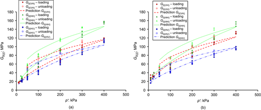
Comparisons between measured and predicted G0(ij) under isotropic loading and unloading cycles for (a) bare specimens; (b) vegetated specimens
Comparisons between measured and predicted G0(ij) under isotropic loading and unloading cycles for (a) bare specimens; (b) vegetated specimens
For vegetated specimens, the presence of roots increased the differences between G0(VH) and G0(HV) and between G0(HH) and G0(HV) (Fig. 8(b)) but decreased the difference between G0(HH) and G0(VH). These effects are due to the predominant vertical growth of vetiver roots, which resulted in a rather anisotropic root distribution relative to the specimen axis. Consequently, the presence of roots further shifted the state of the vegetated specimens away from the cross-anisotropic condition.
Overall, the proposed model for G0(ij), which incorporates the effects of soil fabric and root network, successfully captured the behaviour of G0(ij) in all the shear wave propagation planes in bare and vegetated specimens. The maximum errors between measurements and calculations were always within ±20%. This difference is deemed acceptable given the random nature of shear wave propagation, the challenges and practical difficulties associated with precise measurements of shear wave velocity in the soil (e.g. Ng & Yung, 2008) and the natural variability of root network development observed in vegetated specimens, even under identical environmental conditions.
Figures 9 and 10 show the model predictions of the calibrated G0(ij) model for bare and vegetated specimens, respectively, under various anisotropic loading conditions at different values of η at two initial values of p′ of 100 and 400 kPa, alongside measurements for direct comparison. Notably, the discontinuity found in the measurements and the predictions at η with a value of 0 was attributed to slight differences in void ratio among specimens used in tests and variations in model behaviour following compression and extension stress paths (Fig. 5 and Table 2). At any p′, the values of G0(VH) and G0(HV) for bare and vegetated specimens increased with the rise in η. However, the values of G0(HH) remained nearly constant and independent of η. This dependence is due to out-of-plane stress components along shear wave propagation, which were considered not to affect inter-particle contact normal force. Indeed, Wang & Mok (2008), who used the discrete-element method to study the effects of anisotropic loading on G0(ij), previously demonstrated that the increase in the stress components in the shear wave propagation plane would increase G0(ij), which was due to the rise in the mean normal inter-particle contact forces and the change in their distribution. The fact that the values of G0(HH) remained practically unchanged implies that the soil and root network fabrics did not display any noticeable evolution for the range of stress ratios considered in this study. In the future, the evolution of the fabric of sandy soils upon straining under different stress ratios might be explored by in situ X-ray scanning and tomography.
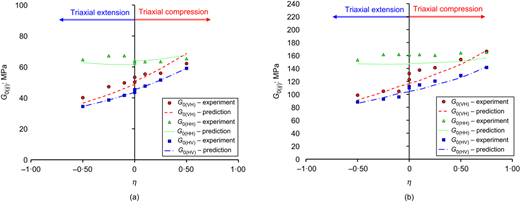
Comparisons between measured and predicted G0(ij) under anisotropic loading for bare specimens at p′ of (a) 100 kPa; (b) 400 kPa
Comparisons between measured and predicted G0(ij) under anisotropic loading for bare specimens at p′ of (a) 100 kPa; (b) 400 kPa

Comparisons between measured and predicted G0(ij) under anisotropic loading for vegetated soils at p′ of (a) 100 kPa; (b) 400 kPa. Notably, no experiments were conducted at the extensive side at p′ of 100 kPa, and only predictions were made for the region of η < 0
Comparisons between measured and predicted G0(ij) under anisotropic loading for vegetated soils at p′ of (a) 100 kPa; (b) 400 kPa. Notably, no experiments were conducted at the extensive side at p′ of 100 kPa, and only predictions were made for the region of η < 0
For a given change in η along compression and extension sides at both values of p′, the value of G0(VH) displayed a greater change (i.e. greater gradient) than that of G0(HV). This difference was more pronounced in the vegetated specimens. First, this discrepancy can be attributed to the fact that the soil fabric was not cross-anisotropic, which was characterised by varying fabric parameters in the horizontal directions (Table 3). Moreover, the anisotropic distribution of roots in the vegetated specimens might have further deviated the soil fabric from the cross-anisotropic condition. The value of p′ appears not to noticeably affect the trend of G0(ij) in bare and vegetated specimens. Given that the mobilisation of the root tensile properties is stress path dependent (Karimzadeh et al., 2021, 2024), the gradients of G0(ij) for η > 0 (i.e. compression paths) should be different from those for η < 0 (i.e. extension paths). The fact that the gradients of G0(ij) of the vegetated specimens were nearly unchanged between η > 0 and η < 0 (Fig. 10) indicates that the level of deviatoric strain applied (i.e. ±2%) was too small to mobilise the root tensile properties, which is consistent with findings reported by previous studies (e.g. Karimzadeh et al., 2021; Meijer et al., 2023). As evidently shown in Figs 9 and 10, the proposed model, with parameters calibrated only against measurements of G0(ij) obtained under isotropic loading conditions, could predict G0(ij) under anisotropic loading conditions reasonably well. The predictions held for either the compression or extension path at any wave propagation planes and any initial p′. Again, given the variability of the interpretation of shear wave velocity and the natural variability involved in the vegetated specimens, the 20% difference between the measurements and predictions of G0(ij) was deemed acceptable. Furthermore, it should be clarified that the proposed model in this study was examined under the coaxial condition. However, under loading conditions where the stress tensor and fabric tensor are non-coaxial, such as during torsional shear conditions where the principal stress axes are subjected to rotation, the proposed theory would require further modification when more relevant data are available in the future.
MODEL EVALUATION FOR TRUE TRIAXIAL TESTS
The ratio G0(VH)/F(e) has been commonly used to evaluate the liquefaction resistance of soil (Andrus & Stokoe, 2000; Amoly et al., 2016). Fig. 11 shows the variations in G0(VH)/F(e) of the bare and vegetated specimens in the deviatoric plane (i.e. various intermediate principal stress ratios; b = (σ2 − σ3)/(σ1 − σ3)) under two different deviatoric stress ratio invariants (R) of 0 (i.e. isotropic consolidation) and 0·5 (i.e. anisotropic consolidation) at p′ = 100 kPa. The value of R, which provides a general definition of deviatoric stress ratios in 3D stress space, can be defined as follows:
where J2D = sijsij/2 is the second invariant of the deviatoric stress tensor with components sij = σij − σkkδij/3; δij is the Kronecker delta; and rij = sij/p is the stress ratio tensor. Anisotropic consolidation (R = 0·5) causes an increase or decrease in the value of G0(VH)/F(e) compared with the isotropic consolidation condition, and these changes depend on the stress path (i.e. the direction and magnitude of loading) and intermediate principal stress ratio (b). Indeed, previous studies have demonstrated that anisotropic consolidation following triaxial compression paths (for R < 0·8) and triaxial extension paths (for any other R) could increase and decrease the liquefaction resistance of the soil, respectively (e.g. Lee & Seed, 1967; Pan & Yang, 2018; Pan et al., 2022), when compared with isotropic consolidation condition. These observations are consistent with the model predictions made in Fig. 11, where the value of G0(VH)/F(e) increased under triaxial compression (solid part of axes 1) and decreased under triaxial extension (dashed part of axes 1), with respect to the isotropic consolidation condition, for the bare and vegetated specimens. Based on the findings given in Fig. 11, soils that follow anisotropic stress paths within the sections I and VI (e.g. stress paths near the crest and the middle part of bioengineered slopes; Karimzadeh et al. (2024)) would exhibit higher liquefaction resistance compared with the case under the isotropic consolidation condition. The reason is that the values of G0(VH)/F(e) in these regions under anisotropic stress paths are consistently higher than those under isotropic conditions, irrespective of the presence of roots. Conversely, this phenomenon would be reversed for stress paths located in sections III and IV (e.g. stress paths near the toe of bioengineered slopes; Karimzadeh et al. (2024)).
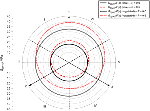
Variations in G0(VH)/F(e) at different sections of the π-plane for R = 0 and R = 0·5 for bare and vegetated specimens, all at p′ = 100 kPa
Variations in G0(VH)/F(e) at different sections of the π-plane for R = 0 and R = 0·5 for bare and vegetated specimens, all at p′ = 100 kPa
CONCLUSIONS
A new model has been developed and implemented to predict the stress-path-dependent anisotropy of G0(ij) for bare and rooted soils in 3D loading conditions. A dimensionless stress-path-dependent anisotropy state variable (A(ij)) is newly introduced in the formulation to account for the effects of loading conditions on the anisotropy behaviour of G0(ij). This state variable can be calculated by projecting soil fabric and root network tensors onto the normal stress within the shear wave propagation plane. The new model enables an explanation and capture of the anisotropy of G0(ij). Two series of triaxial bender element tests were performed on bare and vegetated specimens under isotropic and anisotropic loading conditions at various values of p′ (15 to 400 kPa) and η (−0·75 to 0·75) to validate the model. The 12 parameters required for the model were calibrated using the first series of isotropic tests and then used to predict observations from the second series of anisotropic tests.
The vegetated specimens were less compressible than the bare counterparts because roots occupied voids and restricted the utilisation of some voids by surrounding soil particles. Upon unloading, the vegetated specimens recovered less volume due to the mobilisation of root tensile properties against volumetric expansion. The roots entangled the soil particles, which caused an apparent increase in effective stress and thus in G0(VH) at any values of p′. Furthermore, this effect was observed in G0(HH) and G0(HV) at lower p′ of 100 kPa. Roots reduced the effects of p′ and OC on G0(ij) of the soil because the root network development replaced some stronger soil–soil interfaces with weaker soil–root interfaces. The anisotropic distribution of roots in the soil enhanced the anisotropy of soil fabric and made the vegetated specimens deviate from the cross-anisotropic condition. The values of G0(VH) and G0(HV) increased with a rise in η for bare and vegetated specimens. However, G0(HH) remained practically constant and unaffected by η because out-of-plane stress components had a negligible influence on the inter-particle contact normal force in the shear wave propagation plane and the soil fabric did not evolve for the range of deviatoric stress applied in this study.
Overall, the proposed anisotropy model, with parameters calibrated only against the measurements of G0(ij) obtained from isotropic loading conditions, successfully predicted G0(ij) under anisotropic loading conditions. The proposed model has the potential to predict G0(ij) along any 3D stress paths. By evaluating the ratio of G0(VH) to void ratio function from the model, the effects of stress path on the liquefaction resistance of bare and rooted soils can be efficiently assessed at different sections of a deviatoric plane. The model explains that, compared with the case under isotropic consolidation conditions, the liquefaction resistance of soil may increase due to anisotropic consolidation in slopes in the crest and middle of the slope and decrease due to anisotropic consolidation near the toe of the slope.
Data availability statement
Some or all data used are available from the corresponding author by request.
ACKNOWLEDGEMENTS
The first and second authors acknowledge the financial support provided by the General Research Fund (16202720, 16207521, N_HKUST/603/22) and the Collaborative Research Fund (C6006-20G) funded by the Hong Kong Research Grants Council. The last author would like to acknowledge the support by the Royal Society International Exchanges 2022 Cost Share with the NSFC (IEC\NSFC\223020).
NOTATION
- Aij
dimensionless anisotropic state variable
- b
intermediate principal stress ratio
- Cij
inherent material constant
principal vector of the fabric tensor
- F(e)
void ratio function relating shear modulus to void ratio
- , ,
principal values of the fabric tensors
fabric tensor
- G(ij)
maximum shear modulus in the ij plane
- J2D
second invariant of the deviatoric stress tensor
- Li
universal unit loading vector
- li
unit vector of loading
- pr
reference pressure; 1 kPa
- R
second stress ratio invariant
- , ,
principal values of the root network fabric tensors
root network fabric tensor
stress ratio tensor
deviatoric stress tensor
- t′j
traction of loading moduli
- u(j)i
loading vector perpendicular to unit loading moduli
- vr
reference velocity
- η
stress ratio
- η0|B, η0|R
means of the principal values of and
- Λ(j)i
loading direction along the plane of shear wave propagation
- λ(j)i
unit loading moduli along the plane of shear wave propagation
- ρ
bulk density
- σi′
effective principal stress in direction of i
stress tensor
- Ω1|B, Ω2|B, Ω3|B
principal values of the deviatoric part of
- Ω1|R, Ω2|R, Ω3|R
principal values of the deviatoric part of
REFERENCES
Discussion on this paper closes 1 May 2026; for further details see p. ii.

