With the depletion of mineral resources in recent years, the hanging-wall orebody under the final slope needs to be extracted after opencast working in an open-pit mine. Because of the slope-free face and the special mining position, this process will lead to a significantly different strata movement compared with traditional underground mining. The discrete-element method (DEM) is a common approach to studying mining-induced strata movement considering the influence of the joint. Using DEM, this paper reveals the sensitivity of the strata movement induced by mining under the final slope to the key joint-evaluated parameters (friction angle φ and cohesion c) and obtains the strata movement characteristics under different joint strengths. The main conclusions are as follows: (a) the strata movement is more sensitive to φ than to c; (b) φ is positively associated with the strata movement angle θ, whereas there is no apparent correlation between c and the strata movement angle θ; and (c) there are four primary strata failure modes and three typical strata movement processes under different joint strengths, and the mechanical analysis is given. These conclusions could benefit the back-analysis of strata movement using DEM and understanding the joint impact on the strata movement induced by mining under the final slope.
Notation
- c
cohesion of the joints
- cres
residual cohesion
- E
elastic modulus of the rock masses
- HAx
horizontal force of the roof end
- HAy
vertical force of the roof end
- h
thickness of the stratum
- l
length of the roof
- Mi
bending moment of point i(x i, y i)
- q(x)
pressure acting on the stratum
peak shear stress on a joint in the elastic phase
residual strength
- θ
strata movement angle
mean value of the strata movement angle related to every cohesion
mean value of the strata movement angle related to every friction angle
- ρ
density of the rock masses
- σn
normal stress
- τA
shear stress of the ‘A’ end
- τB
shear stress of the ‘B’ end
- φ
friction of the joints
- φres
residual friction angle
Introduction
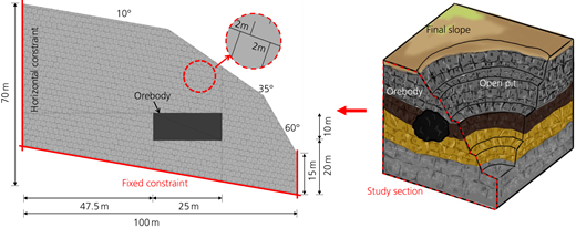
The hanging-wall orebody refers to the orebody located under the final slope of an open pit, as shown in Figure 1. To exploit mineral resources sufficiently, the hanging-wall orebody needs to be extracted after opencast working in an open-pit mine (Tan et al., 2018). This process is also called mining under the final slope. However, due to the shallow buried depth, the non-uniform overlying thickness of orebody, the widely distributed joints and the slope-free face, there is a noticeable difference between the strata movement induced by mining under the final slope and the traditional underground-mining-induced strata movement. Generally, the former is much more complicated and severe. The heavy strata movement presents tremendous challenges to obtaining the orebody safely, and realising the regularity of the strata movement may be the precondition for avoiding relevant accidents. However, limited research has been conducted on this issue. Mining under the final slope is one type of underground mining, and previous studies related to mining-induced strata movement could be helpful for this study.
From the perspective of the research method, usual approaches used in previous studies mainly include the simplified mechanical analysis method, the physical simulation experiment and the numerical simulation experiment. The simplified mechanical analysis method has attempted to illustrate the strata movement by simplifying the strata to the mechanical model and then obtaining the strata movement process or the strata failure modes through mechanical calculation. The classical mechanical models include the pressure-arch theory (Poulsen, 2010), the cantilever hypothesis (Li et al., 2021), the articulated beam (Qin et al., 2022), the voussoir beam theory (Asaei et al., 2018; Talesnick et al., 2007) and the key strata theory (Yang and Luo, 2021). These theoretical models could well reflect the mechanism of the strata movement, and in some cases they could even give a rough prediction of the index value related to the strata movement. However, significant inaccuracy is apparent when the geological condition or the engineering is relatively complicated due to difficulties in simplifying the strata to the exact mechanical models. The simplified mechanical analysis method has been mainly applied to assist researchers in finding the relevant factors of strata movement or roughly analysing the strata movement range. To reveal further the mechanism of the strata movement, the laboratory experiment, which mainly refers to the physical simulation experiment, has been adopted (Castro et al., 2007; Ghabraie et al., 2015, 2017). To a certain extent, the physical model experiment could reflect the process of mining-induced strata movement under a more complicated condition of geology or engineering. However, the deeper mechanism of the strata movement usually could not be investigated due to the limitations of the monitoring method, the difficulty of building complex structural planes in the physical model and economic considerations. With the development of computational mechanics, the numerical simulation experiment has gradually become the priority method used in studying the strata movement because it can easily capture the process of the strata movement and predict the quantity indexes of strata movement. Although various assumptions have been considered in the numerical approach and its results usually differ from the reality, numerous vital conclusions have been obtained through numerical experiments, particularly using the parametric study method. The parametric study method investigates the result with various influence factor values under the same setting. This method could conveniently reveal the impact of potential influence factors. In comparison, this is harder to achieve using an in situ investigation or a physical experiment because of the restriction of the monitoring method and the difficulty of repeatable studies. The continuum-based numerical method, such as the finite-difference method (e.g. FLAC, FLAC3D software programs) and the finite-element method (FEM; e.g. Abaqus, Ansys software programs), is currently widely used (Dudek and Tajduś, 2021; Kim et al., 2019; Kumar et al., 2019; Sertabipoğlu et al., 2020). The continuous method is highly suitable for analysing the stress distribution and the development law of the strata movement under complicated geologic settings or engineering conditions. However, on some scales, discontinuous faces (e.g. joints, faults) may be responsible for the strata failure modes and strata movement characteristics. The continuous method could not substantially reflect the non-negligible impact of discontinuous faces on the strata movement. Therefore, the discontinuous method, which could directly build the complicated discontinuous faces in the numerical model, has been more frequently used for a qualitative or quantitative understanding of the strata movement under the influence of structure planes (e.g. joints, faults) in recent years. The discontinuous method is based on the discontinuous theory; representative methods include the discrete-element method (DEM; e.g. UDEC, PFC3D software programs) and the discrete-element discontinuous deformation analysis (DDA) (Barnett et al., 2020; Chen et al., 2021; Lai et al., 2021; Nguyen et al., 2021; Rahman et al., 2021).
DEM is a Lagrangian numerical technique and was first proposed by Cundall in 1971 (Bobet et al., 2009). The standard DEM algorithm applies two principles for the block interactions: Newton’s second law provides the particle movements, and a force–displacement relationship determines the contact forces between the particles (Cundall and Strack, 1979; Nguyen et al., 2021). A typical process of solving problems with DEM is as follows: (a) discretise the research object into a blocky system, and set reasonable contacts between blocks; (b) obtain the normal and tangential forces between blocks by way of contact force and contact displacement, and the contact force and contact displacement are defined by the block overlap; (c) combine the forces acting in all directions among the blocks and other external forces acting on the blocks, and additionally obtain the acceleration of the blocks according to Newton’s second law of motion; and (d) obtain the velocity and displacement of the blocks by integrating the acceleration (Dong et al., 2018).
Compared with DEM, the DDA approach, originated by Shi, is fundamentally different (Bobet et al., 2009). The basic theory of DDA is the second law of thermodynamics, which states that a mechanical system under loading must move or deform in a form with the minimum total energy of the whole system (Jing, 2003). Furthermore, DDA uses standard FEM meshes over blocks, and the penetration between blocks is prevented by adding springs to the contacts (Bobet et al., 2009; Jing, 2003). In contrast, in DEM, contacts are resolved by defining the contact displacement and forces in terms of block overlap. Compared with DDA, DEM is more mature for large deformation analysis in geotechnical engineering (Dong et al., 2018). Commercial software based on DEM, such as UDEC, 3DEC and PFC, has been widely adopted.
On the other hand, from the perspective of research contents, various potential impact factors for the strata movement have been regarded as research objects and associated with the various quantitative indexes of strata movement. Among these possible factors (e.g. the rock material property, the mining method and the tunnel shape), the joint has been widely treated as the controlling factor that significantly influences the deformation and failure of rock masses (Do and Wu, 2020; Hashimoto et al., 2021; Kumar et al., 2019; Piwowarski, 2019). DEM is extensively used to seek effects originating from joints, and the Coulomb slip with residual strength is the basic constitutive joint model in conventional analysis using DEM (Kuhn et al., 2020; Li, 2013; Liu and Crewe, 2020; Nie et al., 2022). Following the Coulomb-slip model, the contact interaction could be controlled by several mechanical parameters, including the joint normal stiffness (kn), the joint shear stiffness (ks), the joint cohesion (c) and the joint friction angle (φ). The result of simulating a blocky system using DEM is susceptible to these parameters. However, according to the current literature reviewed, the exact relation between these parameters and the strata movement has still not been detailed and systematically described, but the sensitivity of these parameters is crucial in the back-analysis or the prediction of strata movement using DEM.
Mining under the final slope is gradually becoming a necessary task after opencast working in order to conserve mineral resources. The intensive joints are usually widely distributed in an open-pit mine, and the particular mining position intensifies the joint influence on the strata movement. Discontinuum-based simulation could be the priority method to master the regularity of the strata movement induced by mining under the final slope. Based on this engineering background and current research, this paper aims to obtain the sensitivity of strata movement to the representative parameters of the joint (the joint cohesion c and the joint friction angle φ) and attempts to gain an in-depth understanding of the characteristics of strata movement induced by mining under the final slope considering different joint strengths, using a series of numerical parametric experiments based on the DEM software 3DEC.
Research method
The laminated strata, which usually belong to the sedimentary rock mass and frequently appear in open-pit mines and underground engineering, are considered in this paper. In the laminated rock mass, a geological structure usually exhibits what is known as ‘mechanical layering’ where the joints are bounded by the boundaries of the bedding planes and commonly nearly perpendicular to the bedding planes (Bakun-Mazor et al., 2009). Based on the structural features of the laminated rock mass, two sets of orthogonal discontinuous faces were constructed in the model used in this investigation. Besides that, to reflect the common practical geological settings, a slight tilt angle (10°) was set to one group of joints, and the distance between joints was set as 2 m. The setting of the joint is shown in Figure 1.
The height of the research domain was set as 70 m, and the width was 100 m. The distance from the orebody to the left side of the model was 47.5 m, the length of the orebody was 25 m and the thickness of the orebody was 10 m. In this study, the orebody was designed for mining in one step.
The rock material was regarded as a rigid body to simplify the computation with ρ = 2700 kg/m3 and Young’s modulus E = 10 GPa. This simplification could accurately indicate the reality and has been usually adopted in previous studies. The gravitational acceleration g was set as 10 m/s2.
The horizontal displacement of the lateral sides of the model was fixed, and the bottom of the model was fixed in both the horizontal and vertical directions.
The joint mechanical model is responsible for precisely evaluating the strata behaviour in the numerical simulation. In DEM, the most usually used joint model is the Coulomb-slip model. This model could provide a linear expression of joint stiffness and yield limit. Related parameters include elastic stiffness, frictional, cohesive and tensile strength properties and dilation characteristics (Itasca Consulting Group, 2013). According to the Coulomb-slip model, the peak shear stress on a joint in the elastic phase is given by
where c is the cohesion, σn is the normal stress and φ is the friction angle. When the shear stress exceeds , the shear strength would drop to the residual shear strength. The residual strength is expressed by
where cres is the residual cohesion and φres is the residual friction angle. It is evident that joint cohesion c and joint friction angle φ govern the joint strength, and c and φ are also the common parameters obtained from the in situ investigation.
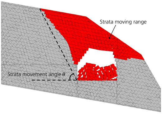
In this paper, c and φ were selected as the study variables, and a comprehensive test was designed (each factor with 11 levels). The strata movement angle (θ) was determined as the result evaluation index to reflect the different impacts of c and φ. The strata movement angle (θ) means the angle between the horizontal line and the line connecting the surface movement boundary and the gob edge at the pillar side, as shown in Figure 2 (Cheng et al., 2017). It could evaluate the moving range of the strata and be usually used as the critical comparative indicator in the parametric study of strata movement. Due to the contact algorithm used in the DEM method, there are inevitable noisy points of the displacement of the model during iterations. The critical value of the surface displacement was determined as 0.1 m, which is much smaller in comparison with the scale of the whole model. Focused on c, φ and θ, a parametric study was conducted to reveal different influence of c and φ on the strata movement angle θ. The other joint-related parameters were set as follows: cres = 0 and φres = φ, as default in the 3DEC software.
The computation was divided into two steps. In the first step, gravity was added to the analysis domain. An in situ stress equilibrium in the analysis domain could be achieved after tens of thousands of iterations. In the second step, the whole of the orebody was excavated at one time, and the strata began to move, and the ground surface of the slope started to deform. After tens of thousands of iterations, the deformation of the whole model gradually stopped.
Results and discussion
Sensitivity of the strata movement to c and φ
The extremum difference analysis was adopted, which is also known as the range analysis method. The extremum difference analysis, which has always been used in the analysis of orthogonal tests or the comprehensive test, could accurately evaluate the degree of correlation between the study factor and the result and find the most relevant factor among the various study factors. In the extremum difference analysis, the influence of the other factors is considered negligible or invariable when the influence of one factor is investigated. In other words, the experiment result change is presumed to be influenced by the change in one factor in the extremum difference analysis. For example, the mean value of the strata movement angle related to every friction angle (, i = 1, 2, …, 11) or cohesion (, i = 1, 2, …, 11) was calculated in this paper, as shown in Table 2. The differences among (i = 1, 2, …, 11) were taken as the only influence of the joint friction angle (φ), whereas the change in was singly caused by the variation of the joint cohesion (c). According to this assumption, the relationship between the strata movement angle and each factor could be revealed. In more detail, the sensitivity of the strata movement range to the joint friction angle (φ) or cohesion (c) could be compared, and the correlation (positive correlation, negative correlation, no significant correlation) between them could also be determined.
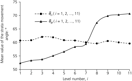
Based on the method mentioned earlier, the sensitivity of the strata movement range to the joint friction angle (φ) and that to the joint cohesion (c) were compared in the following process. The maximum value of the was 70.68° (where i = 11), whereas the minimum value was 52.35° (where i = 1), and the extremum difference value was 18.33°. However, the maximum value of was 62.06° (where i = 3), and the minimum value was 59.62° (where i = 1); the extremum difference value of was only 2.44°. The strata movement range was more sensitive to the joint friction angle (φ) than to the joint cohesion (c) based on the extremum difference analysis within the range of parameters in this paper. In other words, the friction angle of the joints (φ) showed a more extensive influence on strata movement induced by the mining under the final slope than the cohesion of the joints (c).
Correlation of the strata movement with c and φ
The strata movement range under each level of c or φ was investigated separately based on the extremum difference analysis. The curve of the strata movement angle (i = 1, 2, …, 11) against φ i (i = 1, 2, …, 11) and the curve of the strata movement angle (i = 1, 2, …, 11) against c i (i = 1, 2, …, 11) are shown in Figure 3.
The mean strata movement angle (, i = 1, 2, …, 11) of 11-level cohesion (c i, i = 1, 2, …, 11) showed a noticeable fluctuation with the increase in c i. With the cohesion c increasing from 0 MPa (level 1) to 2 MPa (level 2), fluctuated from the lowest value of 59.62° to the highest value of 62.06°, and had no obvious increased or decreased trend under the 11-level cohesion.
However, the mean strata movement angle (, i = 1, 2, …, 11) corresponding to the 11-level friction angle (φ i, i = 1, 2, …, 11) presented a significantly rising trend with the friction angle of the joints (φ) increasing. From 0° (level 1) to 65° (level 11), increased from 52.35 to 70.68°, and the growth reached 18.33°.
The analysis result shows a significant positive correlation between the joint friction angle (φ) and the strata movement angle (θ). With the joint friction angle increasing, the strata movement angle (θ) increases, and the strata movement range decreases. The large joint friction angle (φ) enhances the deformation-resistant capacity of the strata and reduces the mining disturbance effect. Moreover, the influence of the joint cohesion is relatively weaker.
Main failure modes during the strata movement
The numerical simulation showed four types of failure modes of strata movement, and some typical cases were selected to illustrate these failure modes.
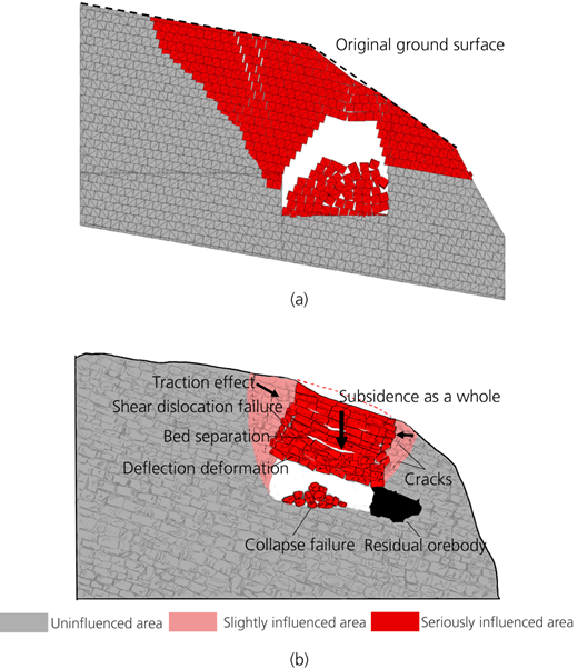
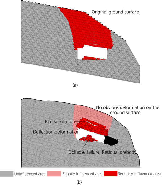
The first type of primary failure mode was the deflection deformation, as shown in Figures 4 and 5. This failure mode typically appeared in the initial phase of the strata movement. With the orebody mined, the roof was slightly bent towards the opening, and the overlying strata were flexed sequentially, but the bending amount was gradually decreased. When the joint strength was lower (c and φ were both lower), the deflection of the stratum would be sustainably developing until the collapse of the stratum occurred. Moreover, when the strata movement ended, the height of the deflection area and the bending amount were closely related to the joint strength. The higher joint strength could significantly weaken the severe deformation. The deflection deformation would be the only main failure mode in the strata with high joint strength, as shown in Figure 5.
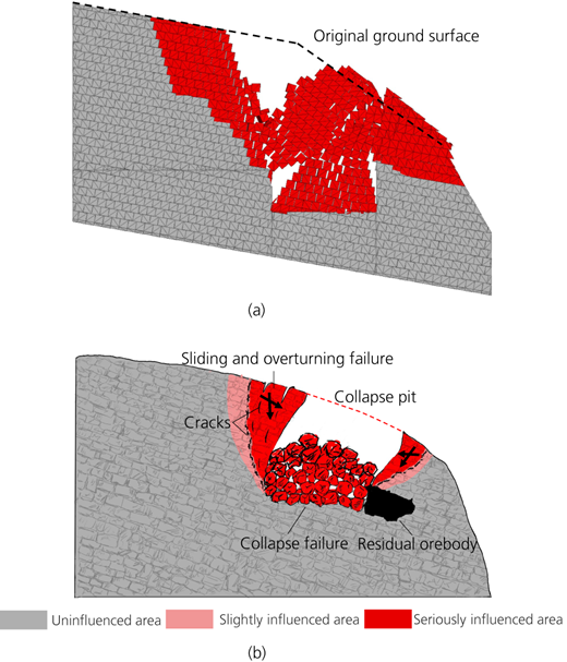
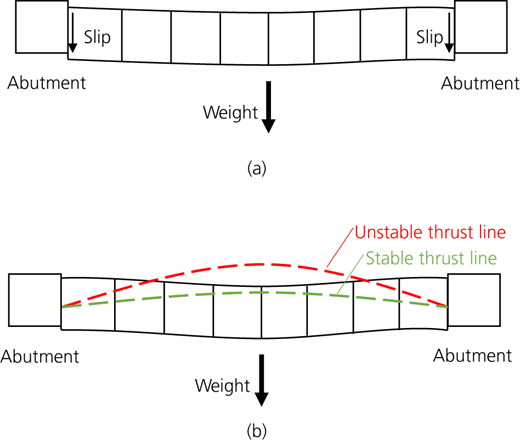
The second type of main failure mode was the collapse failure, as shown in Figures 4–6. This failure usually occurred following heavy deflection deformation. Although the phenomenon was similar when the stratum collapsed (severe fractures or fallings of the rock masses occurred), the mechanisms of this phenomenon were various under different engineering conditions. According to the previous relevant studies, there were two possible mechanisms of the strata collapse failure induced by the mining, including the slip failure and the snap-through failure, as shown in Figure 7.
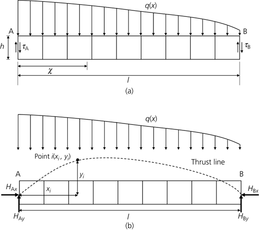
The beam model, which is usually used in mechanical analysis, was conducted to illustrate the mechanism of the collapse failure caused by strata slipping. The stress state of the stratum that would slip is shown in Figure 8(a). The stratum was simplified as a beam with vertical joints for convenient analysis. Additionally, the stability of the beam was highly dependent on the shear resistance provided by the joints. Through mechanical analysis, the maximum shear stress existed at the ‘A’ end of the stratum where the overlying strata were thicker, as shown in Figure 8(a). Following the mining proceeding, the length of the roof was increased, and the shear stress was correspondingly rising. When the shear stress exceeded the joint strength, the slip of the stratum would possibly happen. Simplifying the joints to the horizontal and vertical joints, the shear stresses τ A and τ B (the shear stress of the other end ‘B’) could be calculated as
where q(x) refers to the pressure acting on the stratum. Due to the difference in the overlying thickness, the pressure of every point of the stratum was different; l is the length of the roof; and h was the thickness of the stratum. When τ A and τ B were both bigger than the joint shear strength, the stratum would start to slip as a whole. When τ A was bigger than the joint shear strength and τ B max was less, the bending moment would appear, and the failure modes of the stratum would be complex. Usually, the failure mode would be a superposition of the slip and snap.
The other mechanism of the strata collapse was the snap-through failure. The theory of the thrust line based on the arch structure could be used to assess the possibility of this type of failure (He and Zhang, 2015). The thrust line is a curve representing the positions where the bending moment is zero under vertical loading. When the thrust line exceeded the upper boundary of the stratum, the bending moment would appear, and there would be a high probability of snap-through failure, which is shown in Figure 7. The thrust line of the stratum at the condition of mining under the final slope could be expressed as follows.
Assuming one point i(x,y) located on the thrust line, the bending moment (M i) of this point could be given by
where H A y refers to the vertical force of the roof end, as shown in Figure 8. H A x is the horizontal force provided by the ending of the roof, and the value of H A x was difficult to be confirmed due to its value being influenced by the free face of the slope, the in situ ratio, the joint shear strength and so on. Letting M i = 0, the function of the thrust line could be expressed as
The third primary failure mode was the sliding and overturning failure, as shown in Figure 6. This failure involved the rock masses, which were located obliquely above the mined-out area, sliding or overturning along the joints or the stratification planes caused by the strata self-weight, the overlying weight or the traction from the neighbouring strata. The movement direction pointed to the accessible area produced by the strata subsidence. Following the different conditions, the strata failure could be manifested as sliding, overturning or the superposition of sliding and overturning. Moreover, the influence conditions mainly included the joint attitude, joint strength and relative position between the mining-out area and the moving strata.
The fourth primary failure mode was the shear dislocation failure. This failure typically occurred with a noticeable subsidence and usually appeared around the two sides of the subsidence area, as shown in Figure 4. The disharmony of the strata deformation mainly caused this failure. In other words, the vertical movement of the subsidence area was much larger than that of the other part of the strata, which induced the relative shear disturbance around the dividing line between the main subsidence area and the other area.
Characteristics of the strata movement process
Through the numerical experiments in this paper, the strata movement process was found to have different characteristics with different joint strengths. In detail, there were three typical types of strata movement processes in the numerical experiments. Some representative cases were selected to be analysed to illustrate the characteristics of the strata movement process.
As the joint strength was relatively weaker, the roof strength was weaker, and roof collapse would occur immediately with the mining. The collapse immediately developed upwards until it reached the ground surface. Following the strata collapsing, two areas of stress release were formed located on the two sides of the subsidence area. Moreover, a displacement pointing to the stress release area was produced in the rock masses around the stress release area, as shown in Figure 6.
With the increase in the joint strength, the roof could remain stable with a longer length. Also, the deflection deformation was the initial strata movement mode with the mine excavated. Then, the strata began to collapse, and the overlying strata subsided as a whole due to the adhesion of the joints. The shear dislocation occurred concomitantly around the boundary of the subsidence area. Furthermore, the subsidence strata had a noticeable traction effect on the surrounding rock masses, which led to the generation of tension cracks located obliquely above the mined-out area. This phenomenon was very different from the cases with weaker joints. In the cases with weaker joints, the subsidence area was presented as loose or discrete blocks due to lack of bonding effect between rock masses, and the traction effect on the surrounding rock masses was also slight.
When the joint strength was high enough, the deflection deformation would be the primary deformation mode of the strata movement, and some bed separation would appear concomitantly due to the discrepancy of the bending deformation of the strata.
Conclusion
This paper studied the sensitivity to basic joint parameters (Coulomb-slip model, c and φ) in strata movement induced by mining under the final slope using a parametric study based on DEM. Furthermore, the primary strata failure modes and the typical strata movement process with different joint strengths were also revealed and analysed through some simplified mechanical models. The following are the main conclusions obtained in this paper.
The extremum difference of (i = 1, 2, …, 11) is 18.33°, and the extremum difference of (i = 1, 2, …, 11) is only 2.44°, which means that the strata movement range is more sensitive to the joint friction (φ) compared with the joint cohesion (c). Furthermore, the joint friction angle (φ) is positively associated with the strata movement angle (θ). In other words, with the increase in the joint friction angle (φ), the strata movement angle (θ) increases, which means that the movement range decreases. In comparison, the joint cohesion has no apparent correlation relationship with the movement range in this paper.
Four primary modes of strata failure have been revealed: the deflection deformation, the collapse failure, the sliding and overturning failure and the shear dislocation failure. The deflection deformation typically occurs in the early stage of the strata movement, and it will develop from the roof towards the ground surface. The development speed and the final influence height are closely related to the joint strength. When the strength of the stratum is not enough to support its own weight and that of the overlying rock masses, collapse failure will occur. Further in-depth analysis shows two main mechanisms of collapse failure – namely, the slip failure and the snap-through failure. The beam model could well illustrate the slip failure through mechanical analysis. When the maximum shear stresses of the two ends of the roof τA and τB are both bigger than the joint shear strength, the stratum will slip as a whole. When τA is bigger than the joint shear strength and τB is less, the bending moment will appear and the failure modes of the stratum will be complex. Usually, the failure mode will be a superposition of slip and snap. The thrust line theory is used to evaluate the snap-through failure in this paper. When the thrust line is within the stratum, the snap-through failure will not happen, whereas if the thrust line exceeds the stratum, bending moments will be generated and the snap-through failure will occur. The sliding and overturning failure mainly appears following the collapse. When the collapse occurs, the rock masses around the subsidence area have begun to slide along the joints or the stratification planes. The overturn deformation will happen when the movement is severe. The shear dislocation commonly appears around the two sides of the subsidence area and is mainly caused by the disharmony of the strata deformation.
The processes of the strata movement are different under various joint strengths. Three typical movement processes have been observed when the joint strength is different in this paper. In cases with weak joint strength (c and φ are both lower), the collapse is the leading movement process. With the increase in the joint strength, the bending deformation of the roof and the subsidence of the whole overlying strata have been successively the primary movement mode of the strata movement process. Due to the bonding effect of the joints, the traction effect has been obviously reflected in the strata movement, and the tension cracks have been significantly noticed in the rock masses obliquely above the mined-out area. When the joint strength is further increased, the deflection deformation of strata is the only mode of the strata movement.