


Microbially induced calcite precipitation (MICP) is an emerging biogeotechnical technique that facilitates a bio-cementation process through biomineralisation and which can bond otherwise loose soil particles, thereby increasing the shear strength and stiffness of the soil while decreasing its permeability and compressibility. However, the uniformity of calcite (calcium carbonate) precipitation may have a relatively low ‘certainty of execution’ in situ due to strict environmental conditions required for the reaction, highlighting a strong need for in situ monitoring of the subsurface during and following the treatment. This research explored an electrochemical approach to monitoring MICP treatment through the development and use of potentiometric ion-selective sensors to measure ammonium and calcium ions continuously in both aqueous batch reactors and small laboratory-scale soil test cells. Sensor calibrations indicate a strong and reliable correlation between the electrochemical potential and target ion concentration, which shows promise in sensor technology for monitoring MICP and other similar processes. Improvements to the current design are, however, needed, as fouling due to calcite precipitation, and to some extent biofouling of the sensor, was observed in the highly dynamic, biomineralisation environment, which caused data drift/interference. These effects should be considered in data analysis and eliminated/minimised for eventual adoption towards monitoring the efficacy of MICP treatment in situ.
Notation
Introduction
Biogeotechnics is rapidly developing as a subfield of geotechnical engineering. For example, microbially induced calcite precipitation (MICP) is a biotic geotechnical technique that leverages the biomineralisation process and that stimulates naturally present, augmented or introduced microbial populations within porous media (e.g. natural soils or anthropogenic materials such as the glass beads used as a control in this study) to precipitate calcium carbonate (calcite) in the polymorph of calcite through urease hydrolysis (i.e. the breakdown of urea (CO(NH2)2) into ammonia and carbon dioxide (CO2)). Additionally, other methods exist using natural isolates, such as enzyme-induced calcite precipitation (EICP), which, instead of relying on ureolytic bacteria to produce the urease enzyme, sources it from a natural isolate such as jackfruit. At a small scale, EICP is economical and effective; however, at a larger scale, EICP quickly becomes less economical than MICP (Ahenkorah et al., 2021). Additionally, the bacteria used in MICP being attracted to soil particles facilitates on-particle and particle-to-particle precipitation by providing a nucleation surface for calcium carbonate precipitation (Ahenkorah et al., 2021). The MICP reaction is summarised as
MICP is a relatively new technique and has currently been successful only in small-scale laboratory experiments and a limited number of field-scale studies (e.g. Gomez et al., 2017; Haouzi and Courcelles, 2018; Montoya, 2012; Naveed et al., 2020; van Paassen et al., 2010). The precipitation of calcite can bond otherwise loose soil particles, thereby increasing the shear strength and stiffness of the soil while decreasing its permeability and compressibility (Barkouki et al., 2011; DeJong et al., 2006; DeJong et al., 2010). For example, Barkouki et al. (2011) and DeJong et al. (2006) showed that calcite precipitation in Ottawa 50–70 sand (silica sand with sub-rounded particles of uniform grain size distribution) increased shear wave velocity with increasing calcite precipitation. Gomez et al. (2018) performed cone penetration measurements (cone penetration testing (CPT)) in poorly graded clean sands treated using MICP to 5% calcite content and found a 527% increase in penetration resistance and a 686% increase in shear wave velocity. This technique is expected to be particularly applicable to liquefaction prevention, strengthening of foundation elements, subgrade stabilisation, soil erodibility reduction, settlement reduction, slope stabilisation and even contamination remediation through co-precipitation techniques (Barkouki et al., 2011; Kavazanjian, 2022).
One issue with MICP is that calcite precipitation can be non-uniform due to the strict environmental conditions and composition required for the reaction (Barkouki et al., 2011; DeJong et al., 2022). Due to possible non-uniformity, conventional geomechanical, geophysical or geochemical testing must ideally be performed at a high spatial frequency post-treatment to ensure soil improvement (DeJong et al., 2010, 2013). However, these techniques cannot provide continuous monitoring of the MICP process. Also, changes in environmental conditions (e.g. exposure to acidic groundwater or rainwater) may cause calcite to dissolve back into solution (Wang et al., 2019). These disadvantages in the use of MICP as a soil improvement technique cumulatively create a low ‘certainty of execution’ (Barkouki et al., 2011; Zhang et al., 2023). The current thinking is to use CPT and/or surface geophysics to assess soil improvement post-treatment. However, these would typically be one-time snapshot measurements. Therefore, embedded sensors for in situ monitoring during and following the treatment are desirable, but to the best of the authors’ knowledge, these types of sensors have not been employed or evaluated in previous MICP studies. Also, studies on developing appropriate sensors for monitoring seem non-existent.
Options for sensing would include measuring the engineering properties of the soil such as strength, stiffness and hydraulic conductivities. Although this is possible to some extent by using in situ testing, there are no sensors available to make these measurements directly. This research considered an alternative where chemical reaction by-products were monitored as an indirect measure of calcium carbonate precipitation. As described earlier, MICP is a biological process that requires strict environmental conditions. Therefore, it is common for even bench-scale laboratory experiments not to yield the precipitation of calcium carbonate due to a variety of issues such as bacterial die-off or contamination, which may result in an undesired dominant reaction. As typical methods for measuring the efficacy of MICP are destructive post-treatment testing, the investigator, generally, will not know that the experiment has failed until after the MICP treatment is complete. This is costly on a field scale and may be days to weeks depending on the scale and scope of MICP treatment. The process from inception of the sensing technology to having field-ready sensors will be a relatively long one. The work presented here was the first step at developing sensors that could ultimately monitor calcium carbonate precipitation during the MICP process. The developed sensors were examined to establish their efficacy at monitoring that the MICP reaction was occurring in real time. If successful, future development would be to correlate in real time the concentration of MICP by-product production from the MICP reaction with soil engineering properties such as strength, stiffness and hydraulic conductivity.
Potentiometric ion-selective membrane (PISM) sensors have emerged to be promising in other areas of environmental monitoring; therefore, this research explored the use of PISM sensors as monitoring devices. PISM sensors are electrochemical sensors used to determine the concentrations of an analyte within a gas or solution (Omics International, 2020), which have the potential to show changes in aqueous (biogeo)chemistry in real time that could indicate the efficacy of MICP treatment. A PISM sensor is a type of electrochemical transducer that converts a ‘passive’ potential difference between two electrodes at a zero current into an electrical response signal (Bhalla et al., 2016). The response signal helps understand the composition, structure and function of sample specimens through a response signal proportional to the concentration of analytes (Yunus et al., 2013), such as ions, enzymes, proteins, antibodies, deoxyribonucleic acid, organelles, microbial cells or tissues (Li, 2019). The theoretical relationship, as expressed in the Nernst equation (Equation 1), shows a linear relationship between the sensor response signal and the natural logarithm of the principal ion activity.
where E is the sensor response signal or reduction potential (V); E° is the standard potential (V); R is the universal gas constant (8.314 J/(K mol)); T is temperature (K); n is the ion charge number of the primary ion; F is the Faraday constant (96 500 C/mol); and ai is the reaction quotient or activity of the ion in solution (unitless).
Solid-contact ion-selective electrodes (S-ISEs) are particularly desirable, as they are more suitable for field application and easier to miniaturise than conventional liquid-filled ion-selective electrodes (Schwarz et al., 2018). S-ISEs function by immobilising the biomolecule or ion-complexing compounds (ionophores) on the outer surface of the ion-selective membrane (Jaworska et al., 2015; Schwarz et al., 2018). The immobilisation can be physical, such as adhesion and/or inclusion, or chemical, such as cross-linking and covalent linking (Jaworska et al., 2015). Immobilisation of the ionophore on the outer surface of the ion-selective membrane aids in fast detection and allows for low detection limits (Jaworska et al., 2015). Furthermore, additives such as carbon (C) nanotubes (CNTs) can be included within the ion-selective membrane to increase fidelity and sensitivity or ionophores may be added to enhance selectivity.
The aim was to monitor calcium (Ca2+) and ammonium (NH4+) ion concentrations, as they are prominent in the MICP reaction (Equation I). The developed ion-selective membranes are selective for ions that are known to either decrease or increase in concentration during the MICP process – calcium and ammonium ions. The characteristic chemical changes or by-products resulting from MICP are the reduction in calcium and hydrogen (H+) ion concentrations and increase in ammonium ion concentration.
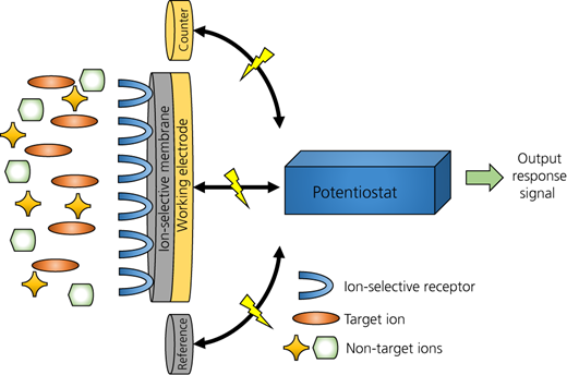
The use of ion-selective membrane electrodes for real-time monitoring of MICP is attractive for their high sensitivity, low detection limit and fast response time (Jaworska et al., 2015). Although this work was focused on the laboratory scale, its design and applications were developed with an eye towards future field applications. A typical schematic diagram of an S-ISE is shown in Figure 1.
Materials and methods
PISM sensors
Reagents and equipment
Reagent-grade high-molecular-weight poly(vinyl chloride) (PVC; 1.4 g/ml at 25°C); tetrahydrofuran (THF); multi-walled CNTs (MWCNTs; 10 μm average length, 12 nm average diameter); 2-nitrophenyl octyl ether (2-NPOE); ammonium ionophore I – nonactin; calcium ionophore IV – N,N-dicyclohexyl-N′,N′-dioctadecyldiglycolic diamide; and potassium tetrakis(4-chlorophenyl)borate (KTCPB) were used without further purification. All aqueous solutions were prepared using doubly distilled and freshly deionised (DI) water (resistance 18.2 MΩ cm, Milli-Q Plus, Millipore). MWCNTs were dispersed in THF through ultrasonication using a QSonica Q500 sonicator for 2 h (200 W, frequency of 24 kHz, amplitude of 70% and a cycle of 0.5 s).
Each of the prepared PISM sensor membrane cocktails (ammonium and calcium) consisted of six components: (a) ionophore; (b) plasticiser; (c) cation exchanger; (d) mechanical stabiliser; (e) sensitivity enhancer; and (f) solvent. These components and their associated functions are described in Table 1.
Functions and materials of each component used in the fabrication of the ion-selective membrane cocktails
| Component | Material | Function |
|---|---|---|
| Ionophore | Ammonium ionophore I – nonactin,a HPLC Calcium ionophore IV – N,N-dicyclohexyl-N′,N′-dioctadecyldiglycolic diamideb | Chemical species that reversibly binds ions of a specific type. Responsible for the selectivity of the ion-selective membrane |
| Plasticiser | 2-NPOEa,b | Improves the adhesions of the polymer to the electrode surface and provides a more uniform distribution of the ionophore in the ion-selective membrane matrix |
| Cation exchanger | KTCPBa,b | Chemical species that can exchange its cations (positively charged ions) with those of a solution passed through it in order to measure the net charge |
| Mechanical stabiliser sensitivity enhancer | PVCa,b MWCNTsa,b | Provides the structural matrix of the ion-selective membrane. Enhances ion transfer and reduces data drift |
| Solvent | THFa,b | Helps dissolve all ion-selective membrane components and provides for rapid drying after drop casting |
Ammonium ion-selective membrane cocktail
Calcium ion-selective membrane cocktail
HPLC, high-performance liquid chromatography
The PISM sensor utilises MWCNTs as a method for immobilisation of the ionophores, which allows for the chemical reaction or analyte to be immobilised at the outer interface of the ion-selective membrane (Jaworska et al., 2015). Although there are many types of immobilisation methods for ionophores (entrapment, encapsulation, covalent binding, cross-linking and adsorption), MWCNTs rely on covalent bonding and provide a high surface-area-to-volume ratio (Saeedfar et al., 2013).
Ammonium ion-selective sensor electrode preparation
The ammonium ionophore cocktail was modelled after a study completed by Huang et al. (2019) and consisted of the following four ingredients: (a) ammonium ionophore I (4.6% weight byxweight (w/w)); (b) 2-NPOE (61.9% w/w); (c) KTCPB (0.5% w/w); and (d) PVC (high molecular weight, 33% w/w). These chemical constituents were then dissolved in a solution of 500 μl THF (≥99.5%) and 2 mg MWCNTs (10 μm average length, 12 nm average diameter).
Calcium ion-selective sensor electrode preparation
The calcium ionophore cocktail was modelled after a study completed by Schwarz et al. (2018) and consisted of the following four ingredients: (a) calcium ionophore I – N,N,N′,N′-tetra(cyclohexyl) diglycolic acid diamide (1.0% w/w); (b) 2-NPOE (65.6% w/w); (c) KTCPB (0.6% w/w); and (d) PVC (32.8% w/w, high molecular weight). These chemical constituents were then dissolved in a solution of 500 μl THF (≥99.5%) and 2 mg MWCNTs (10 μm average length, 12 nm average diameter).
PISM sensor fabrication
The ion-selective membrane cocktails were drop cast onto the 4 mm dia. working electrode surface using a micropipette. This process was completed in four 2.5 μl increments until 10 μl of the ion-selective membrane cocktail was deposited. The electrodes were then placed in a fume hood and allowed to air-dry at room temperature for 48 h prior to use.
Equipment and instrumentation
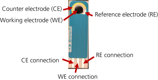
The screen-printed electrodes (SPEs) (Metrohm DropSens, 2020a, 2020b, 2020c), cables (Metrohm DropSens, 2020d), potentiostat (Metrohm DropSens, 2020e) and associated software (Metrohm DropSens, 2020f) are all commercially available. The electrodes used were DropSens screen-printed gold (Au) electrodes (model C220AT), screen-printed carbon electrodes (model C110) and screen-printed graphene (GPH) electrodes (model 110GPH). The ceramic substrate (L 33 × W 10 × H 0.5 mm) was screen-printed with silver (Ag) contacts, leading to the electrochemical cell consisting of a silver reference electrode; gold, carbon or GPH auxiliary/control electrode; and a 4 mm dia. gold, carbon or GPH working electrode. The SPE was connected to a DropSens μStat 400 bipotentiostat/galvanostat through DropSens CAST μStat cable connectors. A typical completed PISM sensor is shown in Figure 2.
PISM sensor assessment
The three SPE substrate types, gold, carbon and GPH, modified with ion-selective membranes were evaluated using ammonium and calcium ion test solutions with known target ion concentrations. The suite of known target ion concentrations tested was made of 1, 2, 4, 8, 16, 32, 64, 128 and 256 mg/l. These concentrations were prepared using stock solutions of ammonium sulfate ((NH4)2SO4) and calcium chloride (CaCl2). The SPE substrate evaluation tests were completed at 20°C under laboratory conditions.
Potentiometric ion-selective sensor temperature assessment
The SPE substrate types gold and carbon were further evaluated for temperature dependence using ammonium and calcium ion test solutions with known target ion concentrations at four different temperatures (15, 20, 25 and 30°C). This temperature range was determined as an adequate representation of expected temperatures for systems in which these sensors may be deployed. The temperatures of the calibration test solutions were maintained using a temperature-controlled water bath. The suite of known target ion concentrations tested was made of 1, 2, 4, 8, 16, 32, 64, 128 and 256 mg/l.
Potentiometric ion-selective sensor assessment for MICP
Each of the ion-selective SPEs was calibrated in test solutions with known target ion concentrations. Initial sensor calibrations of the ammonium ion-selective sensors were performed at known target ion concentrations: 1, 2, 4, 8, 16, 32, 64, 128, 256, 512, 1024, 2048, 4096 and 8192 mg/l. For the calcium ion-selective sensors, the target ion concentrations tested were 0.1, 0.2, 0.4, 0.6, 0.8 and 1.0 mol/l. The calibration tests were completed at 20°C under laboratory conditions.
MICP experimental design and methods
Bacterial solution and growth conditions
The ureolytic bacterium Sporosarcina pasteurii (ATCC 11859) used as part of this study was transferred from a stock culture to an ammonium–yeast extract growth medium (130 mM Tris buffer (pH = 9.0), 20 g/l yeast extract and 10 g/l ammonium sulfate). All growth medium ingredients were autoclaved separately at 121°C/100 kPa for 20 min and combined post-sterilisation. The inoculated growth medium was aerobically incubated at 30°C on a shake plate (300 revolutions per min (rpm)) for 72 h. The final optical density (OD600) of the bacterial growth medium, using uncultured growth medium as a blank, ranged between 1.0 and 1.5 (600 nm; Thermo Scientific Genesys 40/50 visible/ultraviolet–visible spectrophotometer).
Cementation solution
The cementation solution used as part of this study was modelled after the study by Mahawish et al. (2019) and comprised 1 M urea and 1 M calcium chloride. The urea and calcium chloride were sterilised by filtration and autoclaving (121°C, 100 kPa, 20 min), respectively, and combined post-sterilisation.
MICP batch reactor experimental design
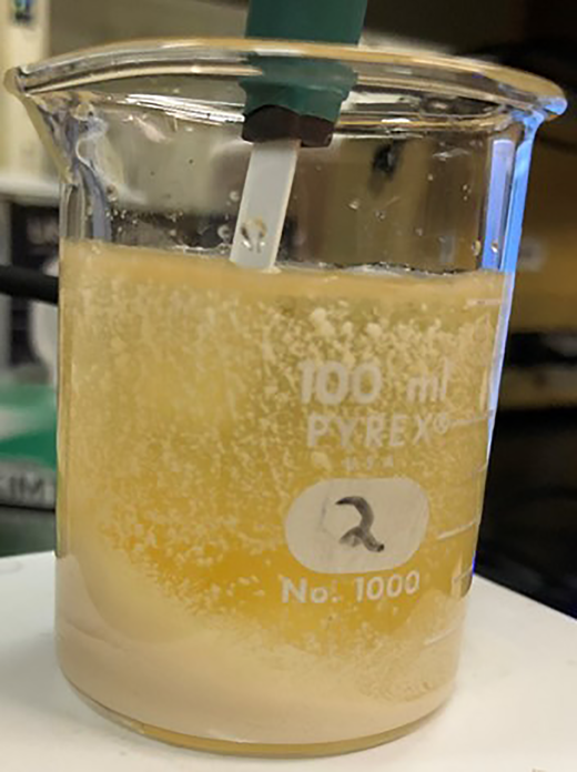
The ion-selective sensors were deployed in an MICP batch reactor (aqueous solution) to monitor changes in ammonium and calcium ions during MICP treatment. The batch reactor consisted of equal parts biological (40 ml) and cementation (40 ml) solutions. The reactor was continuously mixed using a magnetic stirrer at 300 rpm at room temperature. As the potentiostat had a single channel, the batch reactor experiment was repeated for each ion-selective sensor (ammonium and calcium ions). After the two solutions were combined, the ion-selective sensor was lowered into the solution until the working electrode was fully submerged. The zero-current potentiometry (ZCP) method was used to collect sensor measurements at a test frequency of 2 Hz (1 reading per every 2 s) for a 12 h test duration. A photograph of the experimental set-up is shown in Figure 3.
For the MICP batch reactor experiment, the precipitate was collected and washed with DI water by centrifugation (7500 rpm for 15 min). The collected and washed precipitates were analysed to confirm and quantify the presence of calcium carbonate through X-ray diffraction (XRD) and scanning electron microscopy (SEM) analyses.
MICP test cell experimental design
The ion-selective sensors were deployed in a porous medium to monitor changes in ammonium and calcium ions within the pore fluid during MICP treatment. Additionally, a third control sensor was deployed with no ionophore to act as a control for the experiment. Spherical glass beads were selected as the porous media (soil simulant), as they are chemically inert. Therefore, secondary reactions during the MICP treatment process are negligible and any potential changes registered by the ion-selective sensors can be directly attributed to the MICP treatment. The spherical glass beads ranged in size from 250 to 400 μm (Potters Industries, LLC; Blast-O-Lite industrial beads; 40–60 mesh; product 00574244) and classified as a poorly graded sand (SP) according to ASTM D 2487 Unified Soil Classification System (ASTM, 2017). The specific gravity of the beads was 2.58, and the maximum and minimum dry densities, determined in general accordance with the Japanese standard JSF T 161-1990 (JIS, 1990), were 1.689 and 1.527 g/cm3, respectively.
As the MICP technique is likely more applicable to low-relative-density soil conditions, sample specimens were prepared by dry pluviation in a single lift to achieve a dry relative density nearest to 0% (1.527 g/cm3). The mass of specimen needed for each test cell was calculated prior to placement to achieve a 17.5 mm specimen height. The specimen height was selected to centre the working electrode in the middle of the layer of spherical glass beads. The ion-selective sensors were held in place using a three-dimensionally (3D) printed screened sensor housing. The screen was printed to have three slots equidistant across the diameter to accept the sensors. The sensors were then sealed in place using hot glue (Figure 4(a)).
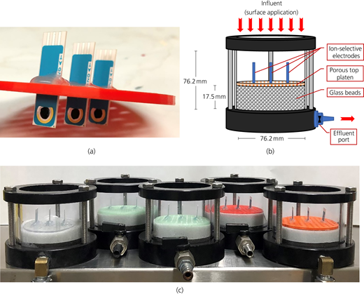
Small-scale, laboratory soil column experiments: (a) ion-selective sensors in 3D-printed screened sensor housing with ammonium, control and calcium sensors (left to right); (b) schematic diagram of a rigid test cell for ion-selective sensor measurements during MICP treatment (not to scale); (c) five rigid soil simulant columns for ion-selective sensor measurements during MICP treatment after 1, 2, 3, 4, and 5 MICP treatment cycles
Small-scale, laboratory soil column experiments: (a) ion-selective sensors in 3D-printed screened sensor housing with ammonium, control and calcium sensors (left to right); (b) schematic diagram of a rigid test cell for ion-selective sensor measurements during MICP treatment (not to scale); (c) five rigid soil simulant columns for ion-selective sensor measurements during MICP treatment after 1, 2, 3, 4, and 5 MICP treatment cycles
The MICP treatment procedure used for this study was adapted from the study by Mahawish et al. (2019), which utilised a four-phase (biological solution → cementation solution → biological solution → cementation solution) percolation strategy. This method is a surface application technique of biological and cementation solutions at defined time intervals and in defined quantities based on the soil pore volume. The process generally included (a) application of the bacterial solution and cementation solution in 12.5% pore volume increments every 24 h; (b) incubation at 20 ± 2°C for 24 h; (c) application of 50% pore volume of cementation solution to the specimen; and (d) incubation at 20 ± 2°C for 24 h. These steps were repeated until the desired number of treatment cycles was achieved. Each repetition was considered one treatment cycle.
Once the desired number of treatment cycles and associated sensor measurements were complete, the specimen was flushed with 1 litre of DI water to remove soluble ammonium salts and then placed in a 110°C oven for a minimum of 24 h to dry. Following oven drying, the MICP-treated specimens were analysed to confirm and quantify the presence of calcium carbonate through XRD and SEM, as well as the calcium carbonate content using a calcium carbonate content chamber.
Specimens were assembled in rigid test cells with internal dimensions of 76.2 mm (diameter) × 76.2 mm (height) (3-inch diameter × 3-inch height) with a valve-controlled drainage port at the bottom of the test cell. The assembly consisted of a bottom platen, porous stone, filter paper, 17.5 mm lift of spherical glass beads and a 3D-printed screened sensor housing with mounted ion-selective sensors (Figures 4(b) and 4(c)). Five rigid test cells were assembled and treated: the first with one MICP treatment cycle, the second with two cycles, the third with three cycles, the fourth with four cycles and the fifth with five cycles. A sensor reading was collected from each sensor at time 0, 1, 2, 4, 8 and 24 h each day until the sample specimen reached the end of its number of MICP treatment cycles. Sensor readings were collected using ZCP with a 1 min test duration to verify the stability of the measurement.
Calcium carbonate detection, quantification and characterisation
Calcium carbonate quantification was performed using a calcium carbonate content chamber (0.374 l, 70 kPa (10 pounds per square inch), Humboldt Mfg. Co., model HM-4501) in accordance with ASTM D 4373-14 (ASTM, 2014), which required dissolving calcium carbonate with hydrochloric acid (HCl) to produce carbon dioxide gas. The amount of carbon dioxide gas produced as part of the reaction was used to estimate the calcium carbonate content of the specimen using a calibration curve specific to the calcium carbonate chamber.
XRD was used to determine the presence of calcium carbonate and to determine in which polymorph it was present. XRD testing was performed pre- and post-MICP treatment. Calcite is the most thermodynamically stable form of calcium carbonate (Krajewska, 2018). Although calcite has a unique intensity profile, its most intense or characteristic peak is located at a 2θ of 28°.
SEM was used to identify visually calcite crystals and their interaction with the spherical glass beads. Imaging was completed on pre-MICP treatment (control) specimens and post-MICP treatment specimens to evaluate the calcite crystal structure and particle to particle bonding.
Results
Effect of the electrode substrate type on PISM sensor performance
Ion-selective membrane electrode substrate type evaluations of gold, carbon and GPH are presented in Figures 5 and 6. Figures 5 and 6 are presented as potential plotted against log10 concentration, which is a common way to present such calibrations and to fit a linear regression. The R2 values for all substrate types indicate good agreement; minimum R2 value = 0.86. These results indicate a good linear relationship between the measured potential and the log of ion concentration. Additionally, the results indicate that the working electrode membrane film does play a role in sensor performance, which can be significant in some cases.
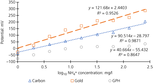
Ammonium ion-selective biogeochemical sensor calibration curves of electrodes with modified working electrode surfaces of carbon, gold and GPH using the ZCP test method: potential plotted against log concentration
Ammonium ion-selective biogeochemical sensor calibration curves of electrodes with modified working electrode surfaces of carbon, gold and GPH using the ZCP test method: potential plotted against log concentration
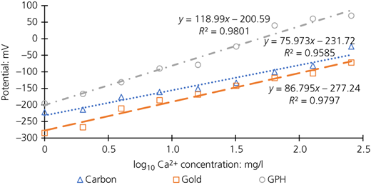
Calcium ion-selective biogeochemical sensor calibration curves of electrodes with modified working electrode surfaces of carbon, gold and GPH using ZCP test method: potential plotted against log concentration
Calcium ion-selective biogeochemical sensor calibration curves of electrodes with modified working electrode surfaces of carbon, gold and GPH using ZCP test method: potential plotted against log concentration
Effect of temperature on PISM sensor performance
The temperature evaluation results of SPEs with ammonium and calcium ion-selective membranes on substrate types, gold and carbon, at four different temperatures (15, 20, 25 and 30°C) were compared with the theoretical values, as calculated according to Nernst’s equation (Equation 1). Temperature evaluation results of SPEs with ammonium and calcium ion-selective membranes on a carbon substrate are presented in Figure 7, and those for a gold substrate are presented in Figure 8.
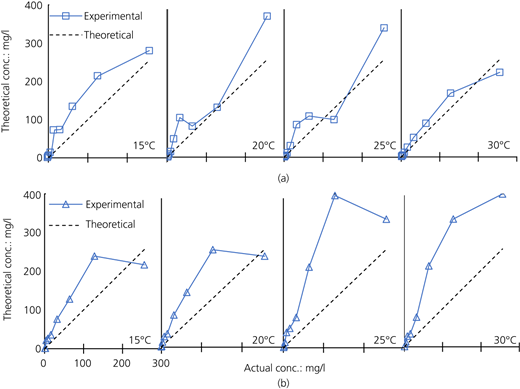
Carbon substrate ion-selective sensor calibrations at 15, 20, 25 and 30°C: (a) ammonium ion-selective sensor with a carbon substrate; (b) calcium ion-selective sensor with a carbon substrate
Carbon substrate ion-selective sensor calibrations at 15, 20, 25 and 30°C: (a) ammonium ion-selective sensor with a carbon substrate; (b) calcium ion-selective sensor with a carbon substrate
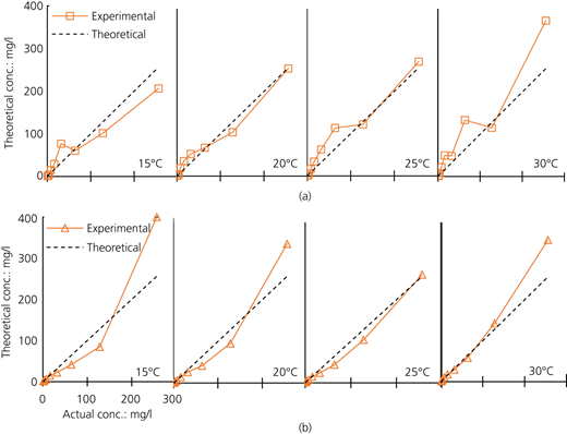
Gold substrate ion-selective sensor calibrations at 15, 20, 25 and 30°C: (a) ammonium ion-selective sensor with a gold substrate; (b) calcium ion-selective sensor with a gold substrate
Gold substrate ion-selective sensor calibrations at 15, 20, 25 and 30°C: (a) ammonium ion-selective sensor with a gold substrate; (b) calcium ion-selective sensor with a gold substrate
Assessment of PISM sensors for monitoring MICP reaction products
Ion-selective sensor calibration
Ammonium ion-selective sensors calibrated in ammonium sulfate solutions are presented in Figure 9(a). The results indicate a good linear relationship between the measured potential and log ion concentration with an R2 value of 0.98. Calcium ion-selective sensors calibrated in calcium chloride solutions are presented in Figure 9(b). The results indicate a good linear relationship between the measured potential and log ion concentration with an R2 value of 0.99.
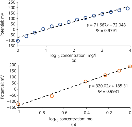
Ion-selective sensor calibration curve of potential plotted against log10 concentration: (a) ammonium; (b) calcium
Ion-selective sensor calibration curve of potential plotted against log10 concentration: (a) ammonium; (b) calcium
MICP batch reactor experiment
Continuous ammonium and calcium ion-selective sensor measurements for the 12 h MICP batch reactor experiments were collected and are shown in Figures 10(a) and 10(b), respectively. The ammonium ion-selective measurements indicate a rapid spike in ammonium concentration followed by a gradual decay, whereas calcium ion-selective measurements indicate a rapid spike followed by a gradual increase until a plateau is reached.
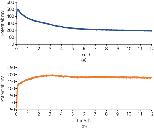
Ion-selective sensor continuous measurements in 12 h MICP batch reactor experiment: (a) ammonium; (b) calcium
Ion-selective sensor continuous measurements in 12 h MICP batch reactor experiment: (a) ammonium; (b) calcium
MICP test cell experiment
Discrete ammonium and calcium ion-selective sensor measurements along with a control sensor measurement for the MICP test cell experiment were collected at 0, 1, 2, 4, 8 and 24 h each day until the sample specimen reached the end of its respective number of MICP treatment cycles. The collected sensor measurements for ammonium ion-selective sensors, calcium ion-selective sensors and control sensors are shown in Figures 11(a)–11(c), respectively. The spikes at each time point indicate the introduction of additional biological or cementation solutions. Similarly to the batch reactor experiment, the results show a temporal decrease in ammonium ion concentration and an increase in calcium ion concentration between 24 h intervals.
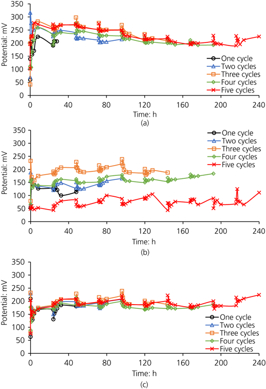
MICP test cell experiment ion-selective sensor measurements from (a) ammonium ion-selective sensors, (b) calcium ion-selective sensors and (c) control sensors
MICP test cell experiment ion-selective sensor measurements from (a) ammonium ion-selective sensors, (b) calcium ion-selective sensors and (c) control sensors
Calcium carbonate quantification as a percentage by mass for the MICP test cell experiments are presented in Figure 12 for one, two, three, four and five MICP treatment cycles. The results show that the percentage of calcium carbonate increases with increased MICP treatment cycles.
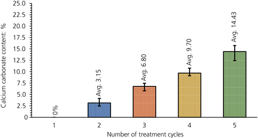
Calcium carbonate content measurements of MICP test cell experiments (one, two, three, four and five MICP treatment cycles)
Calcium carbonate content measurements of MICP test cell experiments (one, two, three, four and five MICP treatment cycles)
Similarly to the batch reactor testing, XRD characterisation of precipitates from MICP test cell experiments shows that calcium carbonate is present exclusively in the polymorph calcite based on the observed characteristic calcite peak at a 2θ of 28° (Figure 13). As indicated in Figure 13, no other substances were detected, including undesired polymorphs of calcium carbonate, such as vaterite or aragonite. XRD testing was completed post-MICP treatment.
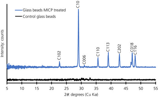
XRD measurement of the precipitate from the MICP test cell experiment for qualification of the presence of calcite
XRD measurement of the precipitate from the MICP test cell experiment for qualification of the presence of calcite
SEM imaging was performed on MICP test cell experiments to confirm calcite deposition. A typical SEM image of a cemented cluster of glass beads with visible particle-to-particle calcite bridging is presented in Figure 14.
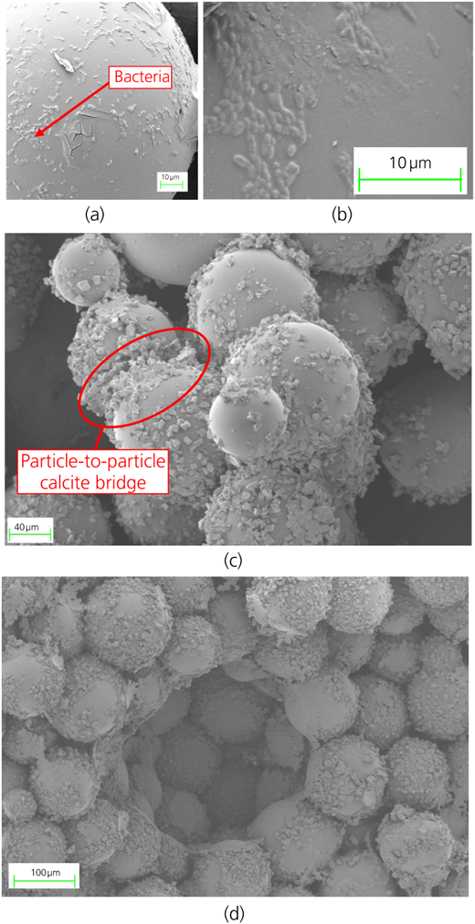
SEM imaging of the MICP test cell experiment showing (a, b) bacteria on a glass bead after addition of bacteria (pre-MICP treatment), (c) cemented cluster of glass beads and particle-to-particle calcite bridges between glass beads (post-MICP treatment) and (d) overall post-MICP treatment structure
SEM imaging of the MICP test cell experiment showing (a, b) bacteria on a glass bead after addition of bacteria (pre-MICP treatment), (c) cemented cluster of glass beads and particle-to-particle calcite bridges between glass beads (post-MICP treatment) and (d) overall post-MICP treatment structure
Discussion
PISM sensor development
A variety of ammonium and calcium ion-selective sensors were evaluated to determine variations based on the electrode substrate (Figures 5 and 6) and temperature dependence (Figures 7 and 8). Although all substrates (gold, carbon and GPH) performed well and showed a good linear relationship between the measured potential and ion concentration with strong R2 values (0.86 minimum), the results indicate that the working electrode substrate does plays a role in sensor performance, which can be significant in some cases. The commercially purchased electrodes use a gold or carbon ink for screen-printing. The GPH sensors are made from a carbon electrode with a layer of GPH applied over the carbon substrate. It was visually observed that this thin layer of GPH was easily damaged by inadvertent contact with another sensor or during drop casting of the ion-selective membrane. For these reasons, the GPH substrate electrodes were not used further in this study.
Temperature dependence evaluations (Figures 7 and 8) were performed only on electrodes with gold and carbon substrates. The results indicate that both gold and carbon substrate sensors showed general trends consistent with the theoretical temperature dependence as calculated using Nernst’s equation (Equation 1). However, sensors with a gold substrate match more closely than those with a carbon substrate. Therefore, gold substrate electrodes were used for final PISM sensor calibration for application in MICP batch reactor and test cell experiments.
Ammonium and calcium ion-selective sensors with gold electrode substrates calibrated in ammonium sulfate and calcium chloride solutions, respectively, indicated a good linear relationship between the measured potential and log ion concentration with R2 values greater than 0.98 (Figure 9). Sensor calibrations also indicated that the sensors were sensitive within the target ion concentration range of the MICP reaction with limited data drift. Triplicate data measurements were taken during calibration testing; however, due to the limited data drift, the error bars were not visible and therefore omitted from the figures.
MICP batch reactor experiment
During the MICP batch reactor experiment, the potential measurement of the ammonium sensor had a rapid spike to its peak potential followed by a gradual decay, whereas the calcium ion sensor had a sudden spike followed by gradual rise to its peak potential and ultimate plateau. These results did not coincide with the expected increase in ammonium ion concentration (increased potential) and decreased calcium ion concentration (decreased potential) based on the stoichiometric equations (Equation I) of the MICP reaction or based on other studies using traditional methods for measuring ammonium ion concentration (phenol–hypochlorite assay) and calcium ion concentrations (complexometric titration) (e.g. Murugan et al., 2021).
Upon completion of the MICP batch reactor experiment (Figure 3), the sensor was removed from the solution. Heavy fouling of the ion-selective membrane was observed (Figures 15(a)–15(d)), which may explain the unexpected trends of the sensor readings. Fouling of the ion-selective membrane surface will both change the working electrode surface area, thereby changing the potential measurements along with changing the micro-chemistry environment around the sensor working electrode. The fouling of the ion-selective membrane and therefore the reduction of the exposed ion-selective membrane are clearly shown in the SEM image (Figure 15(e)) of a fouled ammonium PISM sensor after a 12 h batch test.
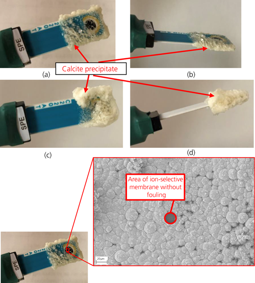
Ion-selective sensor following a 12 h batch reactor experiment: (a, b) ammonium ion-selective sensors; (c, d) calcium ion-selective sensors. (e) SEM imaging of fouling covering the ion-selective membrane of an ammonium sensor following a 12 h batch reactor experiment
Ion-selective sensor following a 12 h batch reactor experiment: (a, b) ammonium ion-selective sensors; (c, d) calcium ion-selective sensors. (e) SEM imaging of fouling covering the ion-selective membrane of an ammonium sensor following a 12 h batch reactor experiment
MICP test cell experiments
Overall, the MICP test cell and batch reactor experiments worked well. Both experimental designs yielded calcium carbonate precipitation in the desired polymorph of calcite and at a nearly 50% higher calcite percentage by mass than that in the study by Mahawish et al. (2019). During the MICP porous medium test cell experiments, the overall trend was similar to that or the batch reactor, which was a decreased ammonium ion concentration (decreased potential) and an increased calcium ion concentration (increased potential) (Figure 11). Again, this was an inverse of the stoichiometric changes of the MICP reaction. In the MICP test cell experiment, there was inter-treatment cycle spikes during solution applications, but the overall trend was consistent with that of the batch reactor experiment (Figures 10(a) and 10(b)). Although the sensors became bio-cemented into the porous media and so extraction was difficult, it was similarly predicted that fouling of the ion-selective membrane that occurred may explain the unexpected trends of the sensor readings (Figure 15).
Both MICP batch reactor and test cell experiments yielded results that did not coincide with the stoichiometric changes of the MICP reaction. In both cases, it was hypothesised that the ion selectivity of the PISM sensors is likely inhibited by the colonisation of bacteria, as well as the preferential nucleation of calcite on bacterial membranes, at the discrete surface boundary of the working electrode. Therefore, this discrete measurement using the ion-selective membrane may not be representative of the global conditions in the volume of the batch and flow cell reactors. This is seen in both experiments where the bacteria metabolising urea would preferentially draw free calcium ions over ammonium ions during the MICP reaction. In the bulk volume of the reactor, this may result in an increase in ammonium ion concentration (increased potential) and a decrease in calcium ion concentration (decreased potential), whereas at the sensor membrane surface, this may result in the opposite trends.
Conclusions
The goal of this study was to explore the efficacy of PISM sensors for use in real-time monitoring of the MICP reaction in aqueous solution as a batch reactor and in repeated applications of an MICP test cell using a porous medium. Specifically, ammonium and calcium ions were tracked. As they were produced in the MICP process, the hypothesis was that by tracking these ions, calcite formation can be tracked, indicating the efficacy of the MICP process. Development and calibration of the PISM sensors yielded high R2 values (0.97–0.99), which indicated that the PISM sensors performed well with monitoring specific/target dissolved species. Although gold, carbon and GPH substrates were tested, the gold substrate performed the best when subjected to temperature changes. However, the soil temperature was relatively constant and may be able to be compensated for in laboratory and field applications.
Although the calibrations showed high-fidelity measurements, sensor deployment in the batch reactor experiment and MICP porous medium test cell experiment did not yield target ion concentration changes pursuant with the stoichiometric equations. It was hypothesised that physical preference of nucleation sites on the ion-selective membrane, along with fouling, biased the resulting potential measurements representative of a discrete point at the surface of the ion-selective membrane. Heavy fouling of the ion-selective membrane of the sensor was visually observed in the batch reactor experiment and was hypothesised to have also occurred in the MICP test cell experiment. However, due to the physical bio-cementation of the sensor in the porous media, the presence of fouling could not be directly confirmed.
Overall, the study showed that PISM sensors show promise for use in real-time monitoring of the MICP reaction, but further work is required to mitigate fouling of the ion-selective membrane to make these sensors viable for real-time in situ monitoring applications.
Practical relevance and potential applications
This is one of the first research studies that attempted to explore potential deployment of low-cost sensors to monitor the MICP process in real time. Other studies have focused entirely on changes in soil properties/mechanics or performed reaction process monitoring by periodic pore fluid sampling, which was later characterised in the laboratory (i.e. not in real time). Researchers envision field verification of MICP treatment using cone penetration testing and shear wave velocity measurements, which are relatively expensive, do not enable continuous monitoring and may not be able to confirm uniformity of treatments due to constraints in spatial distribution of measurements. Once these low-cost sensors are fully developed and validated, the authors envision inserting them in boreholes during initial site investigation, which could be used to monitor soil conditions throughout the treatment process and after.
Although potentiometric biosensors are most commonly associated with medical uses (e.g. blood glucose monitors, pregnancy tests, cholesterol monitors.), biogeochemical sensors, such as PISMs, are also gaining increased use in alternative applications such as environmental biogeochemistry. Similar biogeochemical sensors may be developed to explore other reactions to monitor such as subsurface leaching from landfills, tanks and non-pressurised pipe networks or to monitor changes in soil chemistry to determine agricultural soil fertility.
Ion-selective biogeochemical sensors are not limited to MICP but may also be useful for use in EICP, soil denitrification and so on. Research and development of these small, robust and inexpensive sensors for applications within the environmental fields is growing. Their applications are broad and can be used for monitoring agricultural field nutrient conditions, nutrient loading into waterways through stream bank applications or contaminant leaching detection of waste containment systems. More widespread use of bio-mediation techniques will lead to more sustainable geotechnically related engineering practices, which in many cases will reduce the use of cement, thereby reducing the carbon dioxide footprint while improving public safety.
Acknowledgements
This research was funded by the Vermont Space Grant Consortium under NASA Cooperative Agreement 80NSSC20M0122, which is gratefully acknowledged. The authors would also like to thank Floyd Vilmont and James Catalan for their support with fabrication and implementation of laboratory equipment.

