


Due to the ever-increasing abundance of discarded by-products, it is imperative to develop innovative engineering applications of waste materials, to manage the capacity of landfills. The disposal and landfilling issues associated with tyre waste have necessitated Australian authorities to find innovative applications of tyre waste in pavement construction. In this research, to examine the efficiency of tyre-derived aggregates (TDAs) as a replacement material for quarry aggregates in pavement subbase applications, a series of repeated load triaxial (RLT) tests and wheel-tracker (WT) tests were undertaken on specimens made of proportioned recycled concrete aggregate (RCA) blended with small-sized TDA (TDA-S) and medium-sized TDA (TDA-M), thus merging these two waste materials into a valued pavement-construction material. The results from the RLT and WT tests confirmed that TDA–RCA blends are a suitable alternative for pavement base/subbase materials. Compared with TDA-S, TDA-M resulted in a lower rutting deformation and permanent deformation in WT and RLT tests, respectively. The resilient modulus (M r) of the RCA + TDA-M mix was also found to be higher than that of the RCA + TDA-S mix, and it was almost comparable with the M r of the control RCA.
Introduction
In Australia, approximately 56·3 million equivalent passenger units of end-of-life tyres are generated annually (WMR, 2019). Rather than the costly and environmentally unsustainable landfilling of end-of-life tyres, new markets are constantly being created for the reuse of waste tyres and tyre-derived aggregates (TDAs) in a variety of engineering and non-engineering applications. Tyre rubber is currently used for several engineering and non-engineering purposes, including road surfaces, playground surfacing, concrete paving blocks, ceramic tiles, car brake pads, flooring, drainage and permeable pavements. An initiative action towards research and development of reusing ever-increasing wasted tyres has been developed in Australia to discover innovative applications of waste tyre rubber in pavement applications.
Tyre-recycling companies and road authorities have identified the usage of TDAs in pavements as an ideal method for diverting large quantities of waste tyres from landfills, thus alleviating environmental concerns in terms of tyre disposal. The pavement base/subbase layers are important for the structural performance of the pavement, as these layers absorb traffic loads and distribute them to the subgrade. In recent years, a range of recycled materials has made some inroads into acceptance as pavement construction materials, which includes a range of construction and demolition (C&D) and industrial wastes.
Pavements should provide a long service life under any given climatic and environmental conditions. Hence, the testing of pavement base/subbase materials using large-scale experimental methods such as the wheel-tracker (WT) and the repeated load triaxial (RLT) test, to simulate real traffic loadings and to limit the effect of boundary conditions in small-scale tests, is of increasing interest to researchers and practitioners alike.
Rutting, as one of the principal causes of distress to a pavement system, may occur due to the high tyre pressure of passing vehicles, high ambient temperature and uncontrolled pivot loads. A progressive build-up of permanent deformation causes rutting of the pavement system composed of unbound aggregate base and subbase layers. Rutting resistance is, therefore, a significant performance indicator in pavement design (Walubita et al., 2016). Pavements are furthermore susceptible to other mechanical and environmental disturbing factors such as moisture, surface cracks, fatigue and stripping. The permanent deformation of pavement base/subbase materials incorporating C&D materials is influenced by the deviator stress, moisture content, degree of compaction and confining pressure (Gabr and Cameron, 2012; Zhang et al., 2019). An accurate and precise estimation of rutting is a major challenge due to traffic loading characterisation as well as environmental impacts, which WT tests can provide. A WT test is predominately used for characterising the rutting behaviour of laboratory-scale compacted asphalt mixes. Rutting generally occurs at elevated temperatures, and cracks form in cold temperatures (Mallick et al., 2016). Gabet et al. (2011) performed a round-robin test to analyse the duplicability of a French WT experiment on a polymer-modified bitumen. The study reported certain problems for the mixture, such as overheating of the sample owing to friction and sticking of the binder to the wheel. This study assessed the test procedures and determined that the different tyres used in the round-robin test, peak temperatures and overcompaction of samples could be possible reasons for data scattering. Wang et al. (2016) developed full-depth WT test equipment for examining the effect of the assembly and depth of the pavement structure on the rutting of asphalt pavements with six different structures subjected to elevated temperature conditions. The equipment had the ability to change the loading magnitude, gradient and loading frequency along with controlling and monitoring of the temperature of the mix. It was concluded that the full-depth pavement structure can accurately predict the structure rutting performance closer to the actual pavement conditions due to the stress and strain distribution within the full-depth asphalt. The authors also claimed that improving the rutting performance of the middle-layer asphalt mixture is the most efficient way to improve the overall rutting performance of the asphalt pavement.
Chaturabong and Bahia (2017) used the Hamburg WT to determine the rutting resistance of pavement under both dry and damp conditions to assess the effect of damp conditions in a wet Hamburg WT test on the creep of the pavement. A bitumen bond strength test was also performed to determine the moisture damage on the strength of the bitumen.
Bodin et al. (2009) developed a finite-element constitutive model for analysing the mechanical behaviour of asphalt pavement and validated the model using the results of large- and small-scale WT equipment. The rutting rates of pavement structures tested with both types of equipment using a similar mix design but with two different pavement surface layer materials at similar temperature conditions were found to be very close. The wheel print on the surface pavement layer was also found to be smaller during the motion than the static prints. Inflated tyres showed constant contact stress on an elliptic area, while hard rubber tyre wheels showed an elliptic contact stress distribution on a rectangular area. Zhang et al. (2018) showed that a sustainable asphalt mixture made of low-grade granite aggregates and solid waste-based filler (desulfurisation gypsum residue) and waste tyre rubber-modified asphalt as binder improves the low-temperature crack resistance and fatigue property of the mixture and strengthens the pavement performance.
Tyre recycling is well established in Australia. The tyre-recycling industry is able to process this waste material for pavement construction applications at a competitive rate, compared with traditional quarry materials. The cost difference when using TDA in pavement bases/subbases was found to be nominal compared with other quarry and recycled products, and this was expected to be more competitive over time as the processing cost of TDA is reduced as new markets open up (Arulrajah et al., 2017). TDA processing is energy-intensive, but whole-of-life cycle analysis has indicated that the energy used is no more intensive than that used for the extraction of quarry materials (Arulrajah et al., 2017). TDA has the added advantage of having a much lower density than other pavement aggregates. Hence, the usage of small percentages of TDA (by mass) will result in a larger volume being utilised in pavement base/subbase applications, thus resulting in a better-value recycled product.
Small proportions of TDA have been found to result in a more robust pavement base/subbase system, with less rigidity and cracking, thus resulting in a longer pavement service life (Arulrajah et al., 2019). Arulrajah et al. (2019) evaluated the mechanical strength of samples prepared from three sizes of TDAs blended with recycled concrete aggregate (RCA) for use as pavement subbase materials. TDAs were added in proportions of 1, 2 and 3% by weight to RCAs and subjected to a range of geotechnical tests, including compaction, California bearing ratio and RLT tests. It was indicated that the addition of up to 3% TDA by weight (approximately 10% by volume) generates viable geomaterials for pavement subbase applications.
The current paper reports on part of a comprehensive research study on the usage of TDA for construction of pavement bases/subbases in the state of Victoria, Australia. This study, in particular, investigated the use of the WT test to evaluate the rut resistance of unbound pavement bases/subbases when using recycled products – namely, the rutting resistance of unbound RCA + TDA subbase materials. The performance of base and subbase subjected to the dynamic loading of passing vehicles is commonly characterised by the resilient behaviour of the pavement material. The RLT test has been widely used for the determination of permanent deformation and resilient modulus (Mr) of base and subbase materials. There have also been some trials to optimise the RLT test procedure based on empirical equations to reduce the duration of the test (Nguyen and Mohajerani, 2016). There have been comprehensive studies on the permanent deformation and resilient modulus (Mr) of recycled products including TDA in pavement bases/subbases with the RLT test, but their performance with WT equipment is currently still unknown. The WT equipment was originally developed to test asphalt surface layers only, but it has been adapted to evaluate the performance of pavement base/subbase materials. The outcomes of this study will, therefore, contribute to the current knowledge of waste management and will further enhance the utilisation of recycled materials in future road construction projects. This research adds to the knowledge of large-scale WT test on recycled materials, which is currently being used in road construction projects in Australia and other developed countries to avoid the accumulation of waste materials in landfills.
Materials and methods
TDAs of two different sizes were obtained from a tyre-recycling company in the state of Victoria, Australia. The processing of TDAs in the tyre-processing plant involves the removal of all metals and the shredding, cleaning and screening of waste tyres to form various sizes of TDAs, with a nominal foreign material content. The small-sized TDAs (TDA-S) were composed of 1–3 mm aggregates, and the medium-sized aggregates (TDA-M) ranged from 2 to 4 mm. RCAs with a nominal size of 20 mm were collected from a demolition recycling site in Victoria. A modified Proctor compaction test was carried out on the mixture of RCA and 2% TDA (i.e. both small- and medium-sized) to determine the maximum dry unit weight and the optimum moisture content (OMC) of each blend. AS 1141.23 (SA, 2009) recommends the Los Angeles abrasion test for aggregates larger than 4·75 mm. Since the TDAs used in this study were smaller than 4 mm, the Los Angeles abrasion test on mixtures of RCA and TDA gave the same value of 32·5% as that of RCA alone. Figure 1 shows photographs of the TDAs and RCAs used in the current study. Figure 2 shows the particle size analysis of RCA, TDA and RCA + TDA blends based on ASTM D 6913 (ASTM, 2017). The particle size grading of RCA and RCA + TDA blends was within the limits recommended by the local state road authority for subbase materials (see upper/lower limits in Figure 2). Table 1 shows the results of geotechnical tests on the RCA + TDA blends (Arulrajah et al., 2019). RCA has higher water absorption than natural aggregates due to the presence of residual mortar on its aggregates and its cementitious behaviour (Ganesh et al., 2018; Pandurangan et al., 2016). The increase in absorption capacity has subsequent effects on the degree of compaction (Kim et al., 2018, 2019). The engineering properties of RCA, such as Mr and shear strength, can therefore be improved over time.
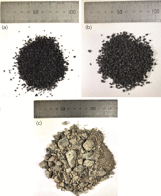
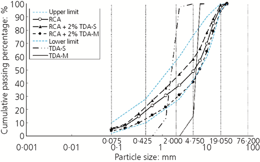
Particle size analysis of the RCA, TDA and RCA + TDA (modified from Arulrajah et al. (2017))
Particle size analysis of the RCA, TDA and RCA + TDA (modified from Arulrajah et al. (2017))
Geotechnical specifications of RCA + TDA blend aggregates (Arulrajah et al., 2019)
| RCA + 2% TDA-M | RCA + 2% TDA-S | |
|---|---|---|
| Gravel content: % | 69·1 | 53·4 |
| Sand content: % | 27·0 | 41·0 |
| Fine content: % | 4·0 | 5·7 |
| Cu (coefficient of uniformity) | 28·8 | 30·3 |
| Cc (coefficient of curvature) | 1·8 | 0·7 |
| Unified Soil Classification System classification | GW | GP |
| Maximum dry density: Mg/m3 | 1·90 | 1·91 |
| OMC: % | 11·31 | 11·20 |
| Loss on ignition: % | 6·2 | 5·1 |
| Permeability: × 10−7 m/s | 4·21 | 1·33 |
In order to determine the permanent strain and Mr of the RCA + TDA blends, a series of RLT tests was undertaken following the Australian road authority method (Austroads, 2007). The blends were compacted into eight layers to form a 100 mm (diameter) by 200 mm (height) specimen at their maximum dry unit weight (at a similar compaction energy used for the modified compaction test) and subsequently dried back to 70% of the OMC in a closed chamber prior to testing to resemble the field conditions. The specimens were sealed using cellophane wrap and cured for 24 h at room temperature prior to the RLT test. The first stage of the RLT test determines the permanent deformation with multiple loading stages at different stress conditions, and the second stage measures the Mr of the specimen. During the first stage of the RLT test (permanent deformation determination), a confining stress of 50 kPa was maintained around the specimen and three different loading stages (deviator stresses) of 250, 350 and 450 kPa were applied at 10 000 cycles each. In the second stage of the RLT test (Mr determination), at least 60 stress combinations including applied dynamic vertical stresses ranging from 100 to 500 kPa and static confining stresses ranging from 150 to 20 kPa were applied on the specimen at 200 cycles each.
In this study, two WT tests were also conducted on RCA + TDA specimens – namely, RCA + 2% TDA-M and RCA + 2% TDA-S (see Table 2) – using a 300 mm depth WT. The width and length of the specimen were 500 and 700 mm, respectively. In order to prepare the test specimen, RCA and TDA were oven-dried at 80 ± 5°C. Proportioned amounts of RCA, TDA and water were mixed thoroughly using a rotary drum. The moisture content of the mix was further checked after the mixing process to ensure that the OMC was reached. The compaction was completed in six layers, each 50 mm thick, to form a 300 mm specimen using a segmented roller compactor that was capable of applying a load of up to 30 kN. A nuclear gauge was used to measure the density of the slab specimen after the compaction process. The density was measured at four different points along with the slab and at three depths of 50, 100 and 300 mm to confirm the uniformity of the specimen density. Table 3 shows the average of measured densities for each specimen. Figure 3 shows the compacted specimen and the WT equipment used in this study.
Testing parameters
| Specimen | Thickness: mm | Compaction parameters | Moisture conditions | Moisture correction: % | ||
|---|---|---|---|---|---|---|
| Target DD: Mg/m3 | Target DD/MDD: % | Target MC: % | Target MC/OMC: % | |||
| RCA + 2% TDA-M | 300 | 1·86 | 98 | 7·9 | 70 | +0·20 |
| RCA + 2% TDA-S | 300 | 1·86 | 98 | 7·9 | 70 | |
DD, dry density; MC, moisture content; MDD, maximum dry density
Dry density (DD) after compaction
| Specimen | Target DD: Mg/m3 | After compaction DD measured by the nuclear gauge:a Mg/m3 |
|---|---|---|
| RCA + 2% TDA-M | 1·86 | 1·69 |
| RCA + 2% TDA-S | 1·86 | 1·69 |
Mean calculated
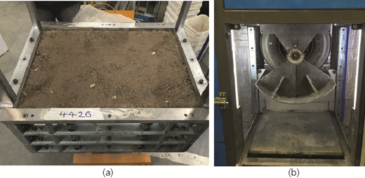
(a) Compacted RCA + 2% TDA-S specimen in the WT tank; (b) WT test equipment chamber
(a) Compacted RCA + 2% TDA-S specimen in the WT tank; (b) WT test equipment chamber
AGP-T054 (Austroads, 2015) recommends that the WT test be terminated when an overall mean deformation of 18 mm is exceeded or when the test has reached the required number of cycles (in this research 40 000 cycles). In this study, a mean deformation of 15 mm corresponding to 5% strain was set as the ultimate service limit of the specimens. However, the serviceability and ultimate limit state methods are not adopted for unbound pavement subbase materials in Australia and several other countries, and instead, the values of Mr and rutting are a more dominant characteristic of pavement design in Australia.
The WT test was carried out on RCA + TDA specimens with an axial load of 8 kN applied on an inflated smooth tyre with an inflated pressure of 600 kPa (Austroads, 2015). The wheel dimensions were 550 mm (diameter) and 110 mm (width) with a set wheel-travel frequency of 0·4 Hz. The deformation during the WT test was recorded using an automated laser scanning device that measured the deformation of the compacted specimen at the end of each loading cycle in five profiles along the specimen. The average deformation was calculated, restricting the area of interest of the wheel-path width (i.e. the contact area between the wheel and the slab) to 110 mm. The average data were restricted to a transverse position between the boundaries ± 55 mm, and the maximum rut depth from each slab surface profile was calculated accordingly. During the course of the experiment, a compacted slab of RCA + TDA was subjected to moving-wheel passes of different loadings. A number of passes were applied until rutting occurred. The rutting depth was characteristically logged for the overall number of cycles, which accounted for a relative assessment of the material’s resistance to rutting.
Results and discussion
RLT test
Figure 4 presents the permanent deformation results of compacted RCA and RCA + TDA blends. The permanent deformation of the RCA specimen was significantly less than that of RCA + TDA blends. The maximum permanent strain of the tested specimens within the three phases of permanent deformation loadings was 2% (i.e. for RCA + 2% TDA-S), which is still lower than the failure limit provided by Austroads (2000). At the turnover to the 450 kPa stress level, the specimen including TDA-S showed a relatively rapid increase in the permanent strain, which may be due to the rearrangement of aggregates to bear the increased imposed load. The RCA + 2% TDA-S specimen contained more fines (sand fraction), and therefore, this weakened the cushioning effect of the specimen, and hence, the overall load-bearing capability of the specimen diminished (Mohammadinia et al. 2019). However, the specimen including larger TDAs showed a lower permanent strain for all deviator stress levels due to the resistance of larger particles to movement under the applied loads.
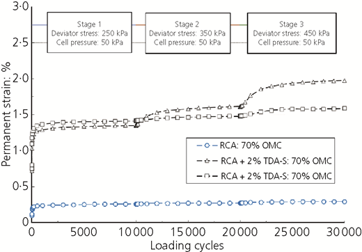
Permanent deformation of RCA and RCA + TDA blends (modified from Arulrajah et al. (2019))
The M r of RCA and RCA + TDA specimens was measured in the next stage of the RLT test under different combinations of confining and axial stresses (see Figure 5). In order to prevent the failure of the specimens at early stages of loading, the test started with higher confining stresses and progressed towards lower confining stresses at a higher number of cycles to simulate harsher load combinations.
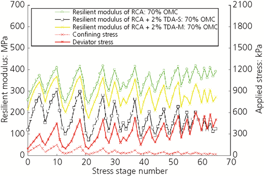
M r and applied stress for RCA, RCA + 2% TDA-S and RCA + 2% TDA-M (modified from Arulrajah et al. (2019))
M r and applied stress for RCA, RCA + 2% TDA-S and RCA + 2% TDA-M (modified from Arulrajah et al. (2019))
The M r of RCA specimen was significantly higher than that of RCA + 2% TDA-S and almost close to the M r of RCA + 2% TDA-M. RCA + 2% TDA-S showed a lower M r compared with RCA + 2% TDA-M, which resisted the applied repeated load significantly. The resilient modulus of RCA + 2% TDA-S and RCA + 2% TDA-M varied between 73 and 305 MPa and 173 and 371 MPa at different stress combinations, respectively. Austroads (2012) recommends a range of 150–400 MPa for the M r of unbound base quality gravel under a thin bituminous surfacing.
WT test
The specimen for WT tests was compacted to 98% of its maximum dry density and 80% of its OMC. The specimen was compacted into six layers using sequential load steps of 5, 10, 20 and 30 kN in multiple passes in the WT tank using a segmented roller until the specimen reached the desired density. Each layer was subsequently air-dried at 38°C in an air-conditioned room until it reached 70% of its OMC and was cured for 4 h. In order to dry back the compacted sample to 70% of OMC, the mould including the sample was moved to a conditioning room at 38°C and set on a balance. The loss of mass of the sample was monitored until the targeted moisture content was reached. The surface of the specimen was then sealed using epoxy products to ensure no moisture loss during testing.
Afterwards, the test specimen was mounted on the WT equipment chamber with a set temperature of 25°C for testing. Figure 6 shows the WT device set up for rut depth measurement sections. The rutting was measured at five different sections in the middle of the box after nominated cycles (0, 10, 50, 100, 200, 500 and 1000) with 405 laser point readings to determine the transversal deformation. The area of laser measurement is highlighted in Figure 6.
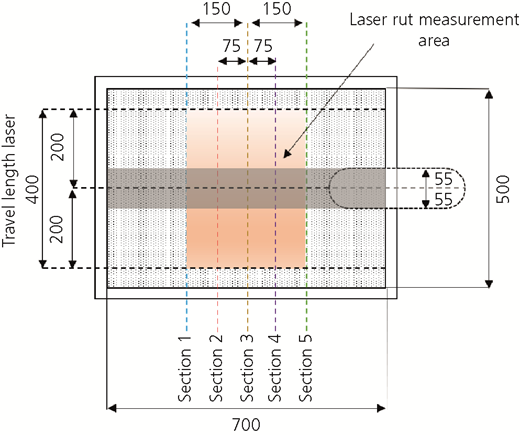
Wheel-tracking device for granular material: location of rut depth measurement points (modified from Austroads (2015)). Dimensions in mm
Wheel-tracking device for granular material: location of rut depth measurement points (modified from Austroads (2015)). Dimensions in mm
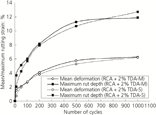
Figure 7 shows three-dimensional (3D) profile data of the WT test on RCA + 2% TDA-S and RCA + 2% TDA-M. These 3D profiles show the initial surface profile and deformation profile (after 1000 cycles). Both specimens failed after 1000 cycles. The maximum rut depth for the blend with TDA-M was greater than that of the blend with TDA-S up to 760 cycles, after which this trend was reversed. However, both specimens failed after 1000 cycles of passes due to excessive rutting (i.e. greater than 5% axial strain).
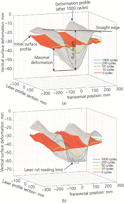
Three-dimensional profile data wheel-tracking test: (a) RCA + 2% TDA-S; (b) RCA + 2% TDA-M
Three-dimensional profile data wheel-tracking test: (a) RCA + 2% TDA-S; (b) RCA + 2% TDA-M
Figure 8 shows profile data of all five cross-sections at different cycles for both RCA + 2% TDA-S and RCA + 2% TDA-M side by side for further comparison. Laser reading for RCA + 2% TDA-M after 500 cycles reached its maximum limit of 25 mm and could not read the final deformation. The WT test results show that the mean deformation and maximum rutting depth were not achieved due to the early failure of the RCA + TDA blends at 1000 wheel passes, which were not enough to capture the end-of-life behaviour of the compacted layers. Austroads (2006) recommends a minimum of 10 000 WT load passes until a mean deformation of 18 mm is achieved as the complete failure of the slab. This level of load passes could not be achieved for the current WT, due to the lack of confinement, as in reality, there would be an asphalt surface overlying the base/subbase that could not be simulated by the current WT due to the restricted 300 mm testing depth. Furthermore, in reality, the pavement comprises several structural layers and to capture the true performance of a WT test, these various layers should also be simulated under the load passes. Thus, the elastic parameters could not be computed for the subbase based on WT test results. The Winkler spring foundation model is usually adopted for rigid pavement design and as such could not be applied for this WT test on unbound materials.
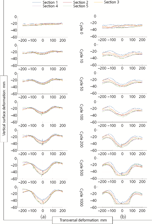
Profile data of all cross-sections at different cycles: (a) RCA + 2% TDA-S; (b) RCA + 2% TDA-M
Profile data of all cross-sections at different cycles: (a) RCA + 2% TDA-S; (b) RCA + 2% TDA-M
Although the small-scale WT is primarily designed for testing asphalt, it has been used with limited success for testing deeper pavement structural layers, and several issues have been encountered when testing recycled materials in bases/subbases and subgrade layers, as evident from the WT results in this study. The following issues were found in this research project with the use of the small-scale WT for RCA + TDA blends in pavement subbases
early rutting failure due to the inability to simulate the full pavement structure
lack of overburden, due to the restricted testing height
inability to achieve the targeted compaction and density
less than ideal compaction with a segmented roller, which shoves the material to the sides
boundary effects due to the small tank size
sealing the surface with epoxy instead of asphalt, due to the restricted height
non-uniform wheel speed
load application from the bottom of the tank
usage of a smaller-than-actual-size tyre.
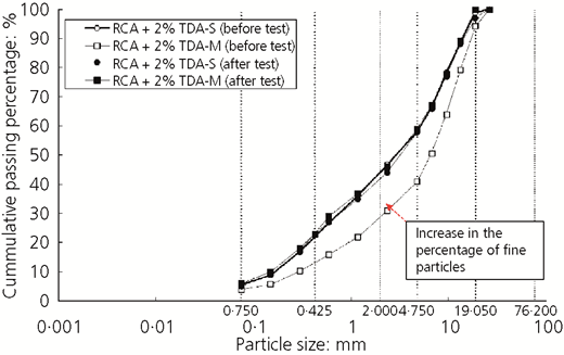
Figure 9 shows the average and maximum rutting strain graphs for RCA + 2% TDA-S and RCA + 2% TDA-M. After completion of the WT test, a dry particle size distribution analysis was carried out on the specimens extracted from the rutted materials underneath the wheel path. Figure 10 shows the particle size analysis of the rutted material compared with the original materials. It is apparent that the aggregates were finer after the test, and it is of interest that the particle size range of RCA + 2% TDA-M approached that of RCA + 2% TDA-S after the test. This suggests that, although the blend of RCA and TDA-M was denser than RCA + TDA-S and required more water to reach the optimum condition, it ended up with the same performance as the RCA + TDA-S blend after 1000 cycles of passes.
Conclusions
The results of RLT tests on mixtures of RCA and two different sizes of TDA – namely, TDA-S and TDA-M – from an earlier study by the authors are reported and discussed. The Mr and permanent deformation of the mixes were evaluated, and the results indicated that the Mr of RCA + 2% TDA-S was significantly lower than that of RCA + 2% TDA-M. Therefore, the RCA + 2% TDA-M blend resisted the applied repeated load significantly and hence resulted in lower permanent deformations at different deviator stress levels compared with RCA + 2% TDA-S.
In this study, in order to verify the RLT test results, two WT tests were carried out on the 300 mm thick compacted RCA + TDA blends. The WT tests on compacted blends resulted in early failure (i.e. at 1000 cycles) for both RCA + 2% TDA-S and RCA + 2% TDA-M mixes with almost similar rutting depths due to the inability of the 300 mm WT test specimen to simulate the full pavement structure and the absence of overburden stress in the WT test. This resulted in a higher deformation of the specimen compared with the peer specimens subjected to RLT test conditions in the presence of confining stress. Although RLT tests showed a discernible difference between RCA + TDA-S and RCA + TDA-M specimens at a large number of cycles, the WT test resulted in almost similar deformation after 1000 cycles for both RCA + TDA specimens.
Overall, the results of this study showed that TDA is a sustainable alternative for substituting RCA. The results also confirmed the superior mechanical resistance of large-sized TDA (TDA-M) compared with that of smaller-sized TDA (TDA-S) in both RLT and WT tests. The challenges with the usage of recycled materials including TDA and RCA in pavements include the requirement to develop new specifications to promote their usage, as well as the need for regulations that will enhance the quantity of recycled products being used in pavement projects. In order for recycled products such as TDA and RCA to be competitive with quarry materials in the short term, incentives to promote the usage of ‘green’ products in road projects would enable recycling companies to increase uptake and over the long run reduce the processing cost of these recycled products.
In this study, shortcomings were noted with the usage of the current large-scale WT tests, adapted from testing of asphalt layers, for testing pavement base/subbase materials. A key recommendation of this study is that a full-scale WT test should be developed that will be able to capture accurately the performance of repeated wheel loads on all components of the entire pavement system (surface, base, subbase and subgrade). This would eliminate the shortcomings of the current WT test, which is restricted by its 300 mm testing depth. A further direction for research would be field trials with TDA, RCA and other recycled materials in road projects, which would demonstrate that the performance of these recycled products is equivalent or superior to that of traditional quarry materials.
Acknowledgements
This research was funded by Tyre Stewardship Australia, as part of a research and development programme on developing new markets for end-of-life tyres. This research was also supported by the Australian Research Council Industrial Transformation Training Centre for Advanced Technologies in Rail Track Infrastructure (IC170100006). The Australian Road Research Board was commercially engaged by the Swinburne University authors to carry out the WT tests. The last author acknowledges the support from the Thailand Research Fund (TRF) under the TRF Senior Research Scholar programme grant RTA5980005 and the Suranaree University of Technology.

