

Clay soil is prone to seasonal volume change due to variation in water content. The use of waste materials in civil engineering, especially in road construction, has been in vogue all over the world due to the development of road infrastructure. Copper slag is one such waste material available abundantly from the copper industry in India. This paper discusses the heave and swelling of copper slag–cushioned clayey subgrade prepared in a model test tank. The results revealed that the methodology adopted is effective in reducing the swelling of clay. The thickness ratios of the stabilised copper slag cushion and clayey subgrade bed adopted are 0.25, 0.5, 0.75 and 1.0. The copper slag cushion is stabilised with lime content varying from 2 to 10%. A reduction in heave of clayey soil subgrade bed is observed with an increase in the percentage of lime and the thickness of the copper slag cushion. For a cushion–clay soil subgrade thickness ratio h c/h s = 1, the reduction in the heave of a clayey subgrade bed is 84.4%. The swell potential observed from the present study follows well the trend obtained from the rectangular hyperbolic model.
Notation
1 Introduction
Swelling soils cause enormous damage to the buildings and pavements. Swelling soils are problematic because the clay mineral constituent which is present in them makes them exhibit shrink and swell behaviour. The shrink–swell behaviour makes the expansive soils unsuitable for construction directly in their natural form (Ikeagwuani and Nwonu, 2019). Expansive soils contain minerals such as clays that are capable of absorbing water. Since change in moisture content leads to swelling and shrinkage, it causes distress in structures; hence, it is mandatory to opt for suitable foundation/stabilisation techniques on these soils to avoid damages to buildings and road pavements due to distress.
Sharma et al. (2008) presented that the amounts of rice husk ash (RHA), lime and calcium chloride that were varied from 0 to 16%, 0 to 5%, and 0 to 2%, respectively, by the dry weight of soil, affected the unconfined compression strength (UCS) and California bearing ratio (CBR) of expansive clay. The stress–strain behaviour of expansive clay improved upon the addition of up to 5% lime or up to 1% calcium chloride. A maximum improvement in failure stress of 225 and 328% was observed at 4% lime and 1% calcium chloride, respectively. It was further concluded that the RHA content of 12% was found to be the optimum regarding both UCS and CBR in the presence of either lime or calcium chloride. The optimum dosages reported were 4% and 1% with respect to lime and calcium chloride even in clay–RHA mixes. Kalkan (2011) studied the effects of wetting and drying cycles on the swelling behaviour of silica fume–modified expansive clayey soils and reported that the silica fume decreases the progressive deformation of modified expansive clayey soils.
The potential of copper slag as a replacement for fine aggregates in bituminous mixes can be a viable option. The mixture of copper slag, fly ash and soil has the potential for use in embankment, sub-base, base and wearing courses of road pavements (Havanagi et al., 2007). The geotechnical properties of copper slag are like those obtained for medium sands; hence, copper slag can be used as a construction material in place of sand, as the backfill of retaining walls and as a fill material in embankment construction. Visser (2007) presented that sometimes, traditional laboratory tests are not able to predict the performance of these materials satisfactorily. Sometimes, conducting trial tests in the laboratory and field is important to identify a suitable stabiliser.
The favourable physico-mechanical characteristics of copper slag mean it can be utilised to make products like cement, fill, ballast, abrasive, aggregate, roofing granules, glass and tiles, apart from recovering the valuable metals by various extractive metallurgical routes (Bipra et al., 2003). Copper slag is a non-plastic material, which has better compaction characteristics than sand, and its permeability is similar to that of sand. The material has a friction angle close to that of well-graded sand, and its use as backfill reduces the active lateral pressure on retaining walls (Dhir et al., 2017). Deviator stress at failure and the elastic modulus of the slag/fly ash/dolime mixes are much greater than those of the wet mix macadam (WMM) (Patel and Shahu, 2017). A mix of 20% fly ash and 80% copper slag stabilised with 15% dolime gave optimum percentage for use in the base course of flexible pavements (Shahu et al., 2013).
Copper slag specimens having 9% cement content and cured for a period of 28 days resulted in maximum compressive strength and tensile strength. Copper slag and fly ash when mixed in optimum proportions and stabilised with 6 and 9% cement can be effectively used as granular material in the sub-base and base layer of road pavement (Raj et al., 2018). Copper slag can be used as a stabilising material for the improvement of problematic soils in embankments, pavement sub-grades and sub-bases. According to Katti (1979), an expansive soil, on saturation, helps arrest the heave below a depth of 1.0–1.2 m, due to the development of cementitious bonds in the soil. Copper slag when mixed with lime or cement can result in added advantage to stabilise expansive clay effectively (Lavanya et al., 2014, 2017). Rao et al. (2008) reported that the fly ash cushion stabilised with 10% cement with thickness equal to that of the expansive soil bed had reduced heave by 75% in the first cycle, and with subsequent swell–shrink cycles, the performance further improved in arresting the heave. The experimental investigation and results are discussed in the following sections.
2 Experimental investigation
2.1 Tests conducted
The laboratory tests are conducted on the untreated and treated soil according to the standard test procedures presented in the Indian standard (IS) code of practices, and they are presented in Table 1.
Tests conducted and their respective codes
| Name of the test | IS code of practice |
|---|---|
| Grain size analysis | IS: 2720 (Part IV) (BIS, 1985a) |
| Liquid limit and plastic limit | IS: 2720 (Part V) (BIS, 1985b) |
| IS light compaction/standard compaction | IS: 2720 (Part VII) (BIS, 1980) |
| Free swell index | IS: 2720 (Part XXXX) (BIS, 1977) |
| California bearing ratio | IS: 2720 (Part XVI) (BIS, 1987) |
| Coefficient of permeability | IS: 2720 (Part XVII) (BIS, 1986) |
IS, Indian standard
2.2 Materials used
2.2.1 Expansive soil
Expansive clay soils are commonly found in the Telangana districts of India. Expansive clay used in the present study was collected from the Gundala Mandalam in the Telangana state of India. The soil collected was initially air-dried, and then the clay lumps were pulverised using a wooden mallet and sieved through a 20 mm sized sieve. Before using the clay soil sample for testing, it was kept in an oven for drying. Initially, the basic tests were conducted on a clay sample, and the basic properties of clay are presented in Table 2. The clay sample plasticity index is 40%, and its free swell index (FSI) value is 220%. The percentage of fine sand fraction present in the soil was 63.
Basic properties of soil
| Property | Value |
|---|---|
| Grain size analysis | |
| Gravel: % | 4 |
| Sand: % | 33 |
| Silt and clay: % | 63 |
| Consistency limits | |
| Liquid limit: % | 75 |
| Plastic limit: % | 35 |
| Plasticity index | 40 |
| IS classification | CH |
| Free swell index: % | 220 |
| Degree of expansiveness | Very high |
| Maximum dry density: kN/m3 | 14 |
| Optimum moisture content: % | 21 |
| California bearing ratio: % | 1 |
| Coefficient of permeability, k: cm/s | 0.53 × 10⁻⁷ |
2.2.2 Copper slag
The copper slag used in the present study was collected from the Sterilite Industries, Tuticorin, Tamil Nadu state, India. The physical properties and chemical composition of the copper slag are presented in Table 3 and Table 4, respectively. Copper slag has a 99% fine sand fraction. The specific gravity of copper slag is 3.6, and its hardness found on Moh’s scale is in the range of 6.5 to 7. The maximum dry unit weight of copper slag is 23.5 kN/m3. The iron oxide and silica mineral compositions are predominant in the copper slag.
Physical properties of copper slag
| Property | Value |
|---|---|
| Grain size analysis | |
| Gravel size: % | 1.00 |
| Sand size: % | 98.9 |
| Silt and clay sizes: % | 0.05 |
| Hardness on Moh’s scale | 6.5–7.0 |
| Specific gravity | 3.6 |
| Plasticity index | Non-plastic |
| Swelling index | Non-swelling |
| Granule shape | Angular with sharp edges |
| Maximum dry density: kN/m3 | 23.5 |
| Optimum moisture content: % | 6 |
| Direct shear test | |
| Cohesion: kN/m2 | 0 |
| Angle of internal friction: ° | 40 |
| Coefficient of permeability, k | 1.54 × 10⁻² cm/s |
| CBR: % | 3.5 |
CBR, California bearing ratio
(Courtesy: Sterilite Industries Ltd, Tuticorin, Tamil Nadu, India)
2.2.3 Lime
Lime is used as an admixture in the study and was obtained from the local market. The hydrated lime obtained has 95% of calcium hydroxide (CaO).
2.3 Sample preparation in model test tank
In this test set-up, galvanised iron cylindrical tanks of size 280 mm dia. and 400 mm height are used. The cylindrical test tank is initially filled with a 15 mm thick sand layer at the bottom and levelled. A 250 mm dia. and 350 mm high thin casing pipe is placed in the cylindrical test tank. Expansive clay soil which was mixed thoroughly at its optimum moisture content is taken and compacted inside the casing in three layers. Each layer of 50 mm thickness, the overall thickness of the clay bed being 150 mm, is compacted to the maximum dry unit weight in the cylindrical test tank within the casing pipe. The expansive clay bed thickness is referred to as h s throughout the paper. Fine-to-medium sand is poured in the gap between the casing and the cylindrical tank up to the height of the proposed cushion. The 15 mm thick sand layer poured around the cylindrical test tank served as a drain to allow water into the soil bed. After clay bed is compacted, the casing is withdrawn slowly until it reached the desired height of 150 mm. A hollow polyvinyl chloride pipe is placed on the top of the expansive soil bed, and a heave stake is placed on the top of the expansive soil bed through the hollow pipe. On top of the heave stake, a dial gauge of 0.01 mm sensitivity is arranged to measure the corresponding soil heave. Copper slag and the desired quantity of lime are thoroughly mixed in dry condition, and then the water corresponding to optimum moisture content is added to it. The percentages of lime added to the copper slag are 2, 4, 6, 8 and 10%. Copper slag, stabilised with lime, is placed over the expansive soil bed and compacted in three layers to its maximum dry density. The copper slag stabilised at different dosages of lime is called the lime-treated copper slag cushion, and its thickness is referred to as h c throughout the paper.
Specimens in the test tanks are prepared for different ratios of thicknesses of lime-stabilised copper slag (h c) and the expansive soil bed (h s). In this study, the thickness of the expansive soil bed (h s) is kept constant as 150 mm. The h c is varied such that the ratio of h c to h s is maintained at 0, 0.25, 0.50, 0.75 and 1.00. Before allowing the water through the sand drain into the expansive clay bed for saturation, the initial dial gauge reading is noted through the heave stake arrangement made in the test tank. Then, water is allowed into the test tank through sand drain for the saturation of the expansive soil. The heave readings are taken corresponding to the attainment of equilibrium. The attainment of equilibrium is considered when there is no change in the dial gauge reading. Corresponding to this equilibrium stage, the undrained cohesion and water contents of the clay soil are measured, and these values are 26 kPa and 65%, respectively. A schematic diagram of the test tank set-up is shown in Figure 1.
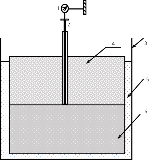
Schematic diagram of the experimental set-up: 1, dial gauge; 2, heave stake; 3, test tank (280 mm and 400 mm); 4, copper slag cushion with admixture thickness h c; 5, all around sand cushion 15 mm thick; 6, expansive clay bed thickness h s
Schematic diagram of the experimental set-up: 1, dial gauge; 2, heave stake; 3, test tank (280 mm and 400 mm); 4, copper slag cushion with admixture thickness h c; 5, all around sand cushion 15 mm thick; 6, expansive clay bed thickness h s
2.4 Kondner’s rectangular hyperbola
Some mathematical models are useful to simulate the non-linear swell−time curves of expansive soils to establish a relationship between observed and predicted values. One such model, the Kondner’s rectangular hyperbola (Kondner, 1963), is used to show the relationship between the time and heave for expansive soils and is presented in Equation 1:
where S = amount of swell corresponding to time T and ‘a’ and ‘b’ are constants.
The constants, a and b, can be obtained by linearising the non-linear curve. The maximum value of the swelling potential can be predicted by using the above equation.
3 Results and discussion
3.1 Influence of thickness ratio, h c/h s, on expansive clay bed
The heave of expansive clay bed laid under the lime-stabilised copper slag cushion of varied thicknesses is measured from the model test tank studies, and the respective results are discussed below. The clay bed of 150 mm thickness laid in the test tank without the lime-stabilised copper slag cushion – that is, h c/h s = 0 – showed a maximum heave of 53.64 mm. Figure 2 presents the variation of heave with passage of time for different cushion–soil thickness ratios, h c/h s = 0, 0.25, 0.50, 0.75 and 1.00, for the copper slag cushion stabilised with 6% lime. From these curves, it is noticed that as the thickness ratio, h c/h s, increases from 0 to 1.00, the heave of the expansive clay bed is decreasing. Especially for thickness ratios h c/h s= 0.50, 0.75 and 1.00, the increase in heave is noticed within a short period of time, and thereafter, almost no change in heave is particularly noticed. The gradual increase in heave of expansive clay bed is noticed up to 28 days in the case of thickness ratio h c/h s= 0.25, and up to 40 days in the case of h c/h s = 0. The ultimate heave of the clay bed is achieved when the further passage of time does not cause any change in heave or maintains a constant value. When compared to the ultimate heave of the clay bed for a thickness ratio of h c/h s = 0, the decrease in the ultimate heave for thickness ratios h c/h s = 0.25, 0.50, 0.75 and 1.00 is 40.2, 68.1, 78.4 and 82%, respectively. It means that at the thickness ratios h c/h s= 0.75 and 1.00, the copper slag cushion treated with 6% lime provides an optimal control of the heave of the expansive clay bed. It is further observed that it took very little time for almost the entire heave to occur when the expansive clay bed was overlain by the cushion. Such similar behaviour was noticed for the copper slag cushion treated with lime dosages of 2, 4, 8 and 10%. The heave-against-time data for copper slag cushions stabilised with lime dosages of 2, 4, 8 and 10% is presented in Tables 5 and 6.
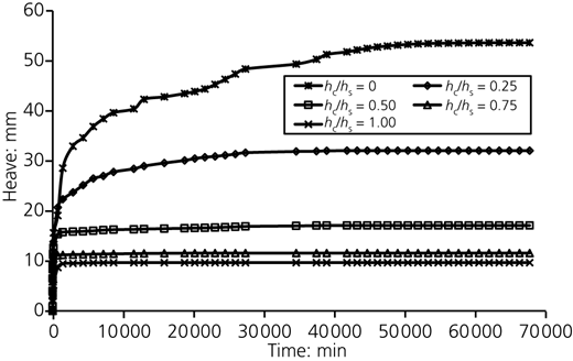
Time–heave plot of expansive soil bed with 6% lime added to the copper slag cushion
Time–heave plot of expansive soil bed with 6% lime added to the copper slag cushion
Measured heave values in millimetres for various thickness ratios, h c/h s, and for lime proportions 2 and 4%
| Time: min | Heave: mm for various thickness ratios, h c/h s, and 2% lime | Heave: mm for various thickness ratios, h c/h s, and 4% lime | |||||||
|---|---|---|---|---|---|---|---|---|---|
| 0 | 0.25 | 0.50 | 0.75 | 1.00 | 0.25 | 0.50 | 0.75 | 1.00 | |
| 0 | 0.00 | 0.00 | 0.00 | 0.00 | 0.00 | 0.00 | 0.00 | 0.00 | 0.00 |
| 1 | 0.09 | 0.22 | 0.59 | 0.78 | 0.27 | 0.50 | 0.20 | 0.31 | 0.06 |
| 2 | 1.16 | 0.77 | 0.87 | 1.32 | 1.6 | 1.10 | 0.50 | 0.86 | 0.30 |
| 5 | 2.93 | 2.08 | 3.3 | 3.31 | 2.51 | 3.00 | 4.12 | 2.91 | 1.19 |
| 10 | 8.42 | 5.63 | 4.51 | 4.69 | 4.26 | 5.24 | 5.08 | 4.11 | 2.52 |
| 20 | 9.99 | 7.99 | 6.52 | 5.43 | 4.26 | 7.40 | 6.85 | 5.05 | 3.43 |
| 30 | 11.03 | 9.08 | 7.39 | 6.26 | 5.24 | 8.70 | 7.92 | 5.71 | 5.18 |
| 60 | 12.68 | 12.29 | 8.67 | 7.87 | 7.92 | 11.72 | 9.76 | 6.74 | 5.18 |
| 120 | 15.62 | 15.75 | 9.55 | 9.52 | 9.33 | 14.50 | 11.35 | 7.66 | 6.16 |
| 720 | 19.08 | 20.44 | 10.09 | 11.29 | 10.72 | 17.50 | 12.55 | 9.85 | 7.65 |
| 1440 | 28.56 | 22.92 | 12.2 | 11.62 | 11.31 | 21.55 | 14.15 | 11.49 | 8.88 |
| 5760 | 36.87 | 27.05 | 13.9 | 12.16 | 12.13 | 25.47 | 15.23 | 11.72 | 10.09 |
| 11 520 | 40.419 | 29.54 | 15.57 | 13.18 | 12.44 | 28.47 | 16.06 | 11.94 | 10.39 |
| 37 440 | 50.32 | 33.39 | 19.08 | 13.85 | — | 31.99 | 17.55 | 12.14 | — |
| 67 680 | 53.64 | 34.67 | 19.29 | — | — | 32.44 | 17.61 | — | — |
Measured heave values in millimetres for various thickness ratios, h c/h s, and for lime proportions 8 and 10%
| Time: min | Heave: mm for various thickness ratios, h c/h s, and 8% lime | Heave: mm for various thickness ratios, h c/h s, and 10% lime | |||||||
|---|---|---|---|---|---|---|---|---|---|
| 0 | 0.25 | 0.50 | 0.75 | 1.00 | 0.25 | 0.50 | 0.75 | 1.00 | |
| 0 | 0.00 | 0.00 | 0.00 | 0.00 | 0.00 | 0.00 | 0.00 | 0.00 | 0.00 |
| 1 | 0.09 | 0.04 | 0.06 | 0.05 | 0.05 | 0.34 | 0.94 | 0.41 | 0.23 |
| 2 | 1.16 | 0.31 | 0.63 | 0.13 | 0.15 | 0.96 | 1.54 | 0.82 | 0.32 |
| 5 | 2.93 | 1.30 | 1.07 | 1.20 | 0.45 | 4.32 | 2.87 | 1.27 | 0.48 |
| 10 | 8.42 | 2.23 | 2.00 | 2.26 | 0.94 | 6.92 | 3.85 | 1.73 | 0.61 |
| 20 | 9.99 | 4.95 | 4.14 | 3.27 | 1.99 | 10.24 | 5.19 | 2.24 | 0.80 |
| 30 | 11.03 | 9.11 | 5.70 | 4.52 | 2.87 | 11.58 | 6.37 | 2.61 | 0.94 |
| 60 | 12.68 | 11.64 | 7.14 | 5.68 | 4.68 | 14.75 | 8.01 | 3.61 | 1.29 |
| 120 | 15.62 | 14.43 | 10.29 | 8.48 | 7.14 | 17.86 | 9.69 | 4.91 | 1.81 |
| 720 | 19.08 | 19.25 | 11.08 | 9.06 | 8.57 | 22.15 | 11.65 | 7.00 | 3.85 |
| 1440 | 28.56 | 22.11 | 11.94 | 9.31 | 8.65 | 24.53 | 12.04 | 7.26 | 5.26 |
| 5760 | 36.87 | 23.02 | 12.54 | 9.60 | 8.89 | 27.88 | 13.10 | 8.45 | 7.51 |
| 11 520 | 40.419 | 24.77 | 13.28 | 10.33 | 9.15 | 29.46 | 13.69 | 8.91 | 8.37 |
| 37 440 | 50.32 | 30.98 | 16.33 | 10.53 | — | 31.13 | 15.33 | 9.62 | — |
| 67 680 | 53.64 | 31.49 | 16.36 | — | — | 31.24 | 15.35 | — | — |
—, not applicable
It is further seen from Figure 2 that a large amount of the heave has occurred in the first two days following inundation, when the cushion was placed on the expansive soil bed. On the other hand, when a copper slag cushion was not provided over the expansive soil bed, the swelling was gradual, and it has taken a long time to attain equilibrium. This is one of the advantages of providing a cushion, as the time required to achieve equilibrium heave has significantly reduced. The percentage decrease in the heave of the expansive clay soil with various thicknesses of cushion when compared with no cushion placed on it is presented in Table 7. It is noticed that there is a significant reduction in the heave with the increase in the thickness of the cushion and with increase in the percentage of lime. The results presented in Table 7 are further depicted in the form of a histogram and presented in Figure 3. From this figure, it is clearly noticed that as the thickness ratio increases from 0.25 to 1.00, the reduction in heave is huge and it can be seen that it is almost the same level for the thickness ratios 0.75 and 1.00. It is also noticed that the influence of lime on the decrease in heave is nominal for any thickness ratio considered in the present study.
Percentage decrease in the heave of expansive soil bed with % lime added to the cushion
| Thickness ratio (h c/h s) | % Lime | ||||
|---|---|---|---|---|---|
| 2 | 4 | 6 | 8 | 10 | |
| 0.25 | 35.37 | 39.52 | 40.23 | 41.29 | 41.76 |
| 0.50 | 64.04 | 67.17 | 68.14 | 69.50 | 71.38 |
| 0.75 | 74.18 | 77.37 | 78.43 | 80.37 | 82.07 |
| 1.00 | 76.81 | 80.63 | 81.99 | 82.94 | 84.40 |
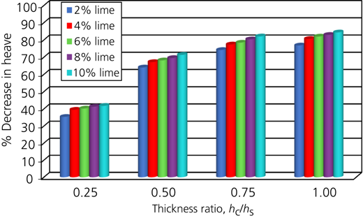
Percentage decrease in the heave of expansive soil with thickness ratio and % lime
Percentage decrease in the heave of expansive soil with thickness ratio and % lime
3.2 Swelling potential from rectangular hyperbola approach
Some mathematical models are useful to simulate the non-linear swell–time curves of expansive soils. Based on the rectangular hyperbola analysis, it is possible to establish a relationship between the observed values and the predicted values of the swelling potential of a lime-stabilised copper slag cushion–soil system. Kondner’s rectangular hyperbola (1963) equation presented in Equation 1 is used to establish the relationship between the time and heave for expansive clay. A graph is plotted between time (as the abscissa) and time/swell (%) (as the ordinate). The legitimacy of the above equation can be demonstrated, if a transformed plot results in a straight line. The constants ‘a’ and ‘b’ are obtained from the slope of the straight line. The value ‘b’ gives the slope of the swelling path. The term ‘b’ is defined as the coefficient of the rate of swelling (Al-Rawas and Goosen, 2006; Hashim and Muntohar, 2006). A typical plot of time against time/swell (%) for different thickness ratios, h c/h s = 0, 0.25, 0.50, 0.75 and 1.00, of expansive soil bed with 6% lime-stabilised copper slag cushion is shown in Figure 4.
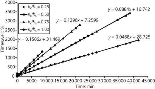
Time plotted against time/swelll (%) of expansive soil bed with 6% lime added to the copper slag cushion
Time plotted against time/swelll (%) of expansive soil bed with 6% lime added to the copper slag cushion
Figures 5–9 show the typical graphs of the predicted and the observed swelling potential of the expansive clay for various thickness ratios and copper slag cushions which are stabilised with various percentages of lime. It can be seen that there is a close agreement between the predicted values of the swelling potential from the rectangular hyperbola and the observed values from the experimental work. The percentage decrease of observed and predicted values of the swelling potential of expansive clay soil with various thicknesses of the cushion when compared with no cushion placed on it is presented in Table 8. Earlier researchers have also observed that the hyperbolic relationship is accurate for predicting maximum swelling (Dakshanamurthy, 1978; Waddah et al, 1999). The percentage error is calculated for the predicted and observed values of the swelling potential. The percentage error of the lime-stabilised cushions for various percentages of lime is 1.61, and the corresponding regression coefficient, R 2, obtained is 0.998.
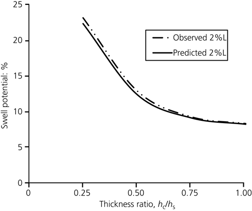
Predicted and observed values of swell potential of expansive soil bed with 2% lime added to the copper slag cushion for various thickness ratios
Predicted and observed values of swell potential of expansive soil bed with 2% lime added to the copper slag cushion for various thickness ratios
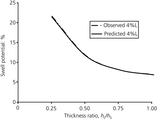
Predicted and observed values of swell potential of expansive soil bed with 4% lime added to the copper slag cushion for various thickness ratios
Predicted and observed values of swell potential of expansive soil bed with 4% lime added to the copper slag cushion for various thickness ratios
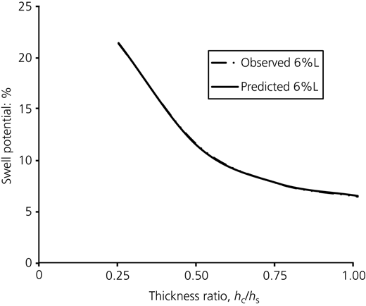
Predicted and observed values of swell potential of expansive soil bed with 6% lime added to the copper slag cushion for various thickness ratios
Predicted and observed values of swell potential of expansive soil bed with 6% lime added to the copper slag cushion for various thickness ratios
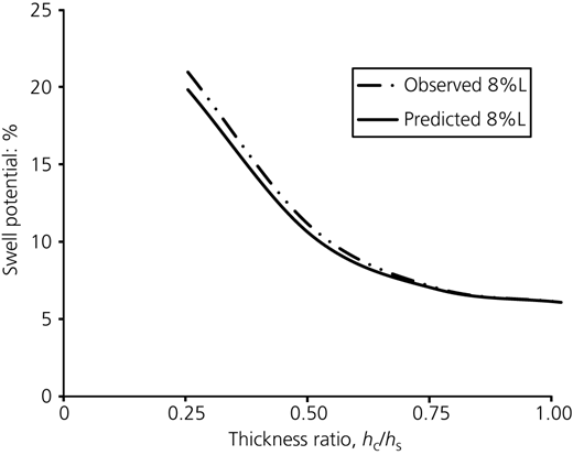
Predicted and observed values of swell potential of expansive soil bed with 8% lime added to the copper slag cushion for various thickness ratios
Predicted and observed values of swell potential of expansive soil bed with 8% lime added to the copper slag cushion for various thickness ratios
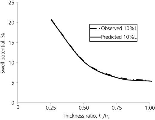
Predicted and observed values of swell potential of expansive soil bed with 10% lime added to the copper slag cushion for various thickness ratios
Predicted and observed values of swell potential of expansive soil bed with 10% lime added to the copper slag cushion for various thickness ratios
Observed and predicted swell potential values (%) of expansive soil bed when lime is added to the cushion
| % Lime | Values | Thickness ratio (h c/h s) | |||
|---|---|---|---|---|---|
| 0.25 | 0.50 | 0.75 | 1.00 | ||
| 2 | Observed value | 23.11 | 12.86 | 9.23 | 8.29 |
| Predicted value | 22.29 | 12.35 | 9.09 | 8.21 | |
| 4 | Observed value | 21.63 | 11.74 | 8.09 | 6.93 |
| Predicted value | 21.40 | 11.64 | 8.10 | 6.87 | |
| 6 | Observed value | 21.37 | 11.39 | 7.71 | 6.44 |
| Predicted value | 21.42 | 11.31 | 7.73 | 6.51 | |
| 8 | Observed value | 20.99 | 10.91 | 7.02 | 6.10 |
| Predicted value | 19.85 | 10.38 | 6.94 | 6.09 | |
| 10 | Observed value | 20.83 | 10.23 | 6.41 | 5.58 |
| Predicted value | 20.67 | 10.07 | 6.18 | 5.39 | |
4 Conclusions
There is a considerable reduction in the heave of expansive soil subgrade bed when a lime-stabilised copper slag cushion is laid over it. With an increase in the percentage of lime, there is a reduction in heave, but it is marginal. However, the increased cushion thickness resulted in a significant reduction in heave. At all the thickness ratios, hc/hs = 0.25, 0.50, 0.75 and 1.00, the decrease in the heave of the expansive soil subgrade overlain with a lime-stabilised copper slag cushion when compared to the expansive soil subgrade bed without a cushion varies from 35.4 to 84.4%. The swelling potential of soil subgrade is predicted by using the rectangular hyperbola method of analysis. The predicted and observed values of swelling potential of expansive soil subgrade bed have been shown to vary by 1.61% for all the thickness ratios. It is concluded that the thickness ratio hc/hs = 1 is effective in controlling the heave.

