

The authors' paper prompts me to offer a few points in amplification of their propositions. First, however, I submit a correction to their suggestion that the jet-grout cut-off at Codbeck reservoir (their reference to Bell, 1993), was constructed from river bed level prior to raising a new dam.
I worked there for the general contractor on my first field contract as an undergraduate trainee in 1951, when the dam was first constructed. The original cut-off was built within a hand-excavated, timber-frame-supported open trench. This was backfilled with puddled clay, heeled into place to form the cutoff. On the left abutment, in bedded shaley clays, at some 20 m or more depth, a thick seam of fine uniform sand was encountered, which liquefied owing to the hydraulic conditions induced by the method of construction and groundwater control by sump pumping.
Ordinary Portland cement injections were unsuccessful in stabilising the sand, and grout appeared in the river bed about 1 km downstream. I left to resume the university term, but I believe the cut-off was completed by a combination of dewatering methods otherwise as planned. In service, over many years, the left abutment was troubled by seepage problems, which were never wholly resolved by a variety of approaches.
Therefore the jet-grouted cut-off referred to by Bell, details of which I am not aware, must have been installed through the clay diaphragm in the body of the existing dam via cased access boreholes.
This leads to my first comment. Such access holes, for any similar works, must be installed within tight tolerances on verticality, or be of sufficiently large diameter, if they are not to encroach on the vertical alignment of the jet monitor and drill string. This requirement becomes more stringent with increasing depth. It is crucial to verticality at lower elevations that the jet drill string be as practically close as possible to vertical at the bottom of the access casing: there must be no misalignment due to encounters with the casing.
Regarding the alignment of jetting, the European standard EN 127161 allows a possible total distance off centre at 20 m depth below the drill of 400 mm (2% of depth). To this must be added a potential 50 mm allowance for inaccurate centring of the drill, totalling 450 mm or 1 horizontal to 44 vertical. This is impossibly lax for the construction of an impervious cut-off of columns 1–1·5 m diameter, as the authors have adduced.
If the jetting-rod string is used to drill the hole, to be subsequently enlarged by the jets during the withdrawal of the monitor, it is equally important for the same reasons that the hole be vertical. In coarse alluvium, or soils offering irregular resistance, it is unlikely that 1 horizontal to 75 vertical will be bettered, which is not accurate enough for a deep cut-off. Therefore it is prudent to advance the rods slowly, and use the radial jets in a pre-wash phase during the downward pass. This enlarges the bore to the order of 400 mm diameter in almost any erodible soil because the jet is most intense close to the monitor.
In a bore of such size the string hangs like a damped pendulum suspended in a heavy fluid. Gravity provides a natural centralising force. A similar situation applies during the jetting withdrawal phase when the hole is further enlarged to its maximum diameter. So, provided the drill string is not impeded by the access casing nor the restricted diameter of the initial drill hole, its verticality will depend almost exclusively on the accuracy of the drill set-up.
Assuming that the worst practical deviation from vertical during drill set-up is 1 horizontal to 250 vertical (this can be seen by eye) a calculation as in the Appendix shows that the maximum deviation from vertical gradually increases to a depth of roughly 16 m when it is about 47 mm. At greater depths this reduces, as the weight of additional drill rods drags the string more towards the centre despite the stiffness of the rods. For example, at about 30 m depth the deviation reduces to 31 mm off centre.
This emphasises the importance of an accurate drill set-up. Provided set-up accuracy is assured and a pre-wash phase is used, with or without grout as the fluid, there should never be a problem with verticality of jet-grouted bores in erodible soils.
I also comment on column diameter at large depths. Covil and Skinner2 list the following hydrodynamic factors as contributing to erosion of the soil: the kinetic energy of the jet; the ‘hammer head’ force of a moving jet; wedging and impact of the jet mass; and cavitation (tensile action in the soil). There must also be some ‘soil’ factors, such as its shear strength, and related pore pressure changes induced by the jet. It is not clear what the relative importance of all these factors is for achievable column diameter.
The soil pore water pressure increases with depth below the water table. The jet pressure, by contrast, remains more or less constant at any given radius from the jet orifice. Although the pressure at the orifice is very high relative to the soil pore water pressure, it declines rapidly with increasing radius from the source. Breusers and Raudkivi3 give an equation relating pressure and jet radius for a water jet operating below water. Using this as an approximation to jet grouting conditions in a borehole, by equating jet pressure to soil pore pressure the jet radius at which pore pressure exceeds jet pressure can be shown. Somewhat surprisingly, it is only about 0·3 m at about 30 m below the water table, to 0·4 m at 15 m for jet orifice pressures of the order of 35–40 MPa. Doubling the depth below groundwater can thus have a significant effect on this aspect of eroding a column. Quantitively, doubling the depth below the water table from 15 m to 30 m can reduce this radius by about 8 cm—not insignificant in relation to column radius (10–16%).
In so far as column radius must be related to soil strength, and that in turn to soil porewater pressure changes, the inability of the jet to raise the pore pressure beyond such a short distance must be reflected in the resulting column diameters at depth.
Finally, I recall that it was inferred from a jet grouting trial at Pergau dam in Malaysia that while the permeability of columns may be low, that of contact joints was probably about 10−7 m/s. I suggest that only if adjacent columns are constructed within 48 h of each other might they coalesce and so lower the permeability of the contact. This is not easy to accomplish in a practical situation. If the joints leak, the only security is in a wide cut-off, as indicated in the theoretical paper by Ambraseys.4 This is hardly cost-effective with jet grouting.
Authors' reply
The authors gratefully acknowledge Dr Greenwood's contribution, and take note, in particular, of the correction about the jet grouting cut-off at Codbeck reservoir.
Concerning the specific point raised in the discussion about the reduction of column diameters with depth, it is recalled that jet grouting can be performed with such a variety of techniques (single-, double- and triple-fluid) and energies that large column diameters can be obtained, even at large depths below the water table.
However, the paper is concerned mainly with the occurrence of discontinuities along the cut-offs, which may derive from misalignment of the treatment axes and from variation of the jet columns' diameter. Both factors were investigated by the authors by means of statistical analyses performed on the basis of direct measurements. It may be useful to provide further information on this topic.
The most reliable data on jet column diameter were gained from the cases of Vesuvius5 and Polcevera.6 For each group of data it is possible to identify an average value, which depends on soil properties and treatment parameters, and a coefficient of variation, which is inherent to the jet-grouting technique.
The dependence of the average diameter on soil shear strength and on treatment parameters has been modelled by Modoni et al.,7 using a deterministic approach. With regard to the coefficient of variation, the available data show a clear dependence on soil heterogeneity, but more information is needed in order to gain proper design values. In any case, experimental data on both the average value and the variation of column diameters could be gained by proper field trials before cut-off construction.
With regard to drilling verticality, the only experimental data available to the authors pertain to the case of the Isola Serafini weir, reported in the paper. These data show a normal distribution for the angle α, with a standard deviation equal to 0·07°. Clearly, the degree of verticality will change for each particular case, depending on the soil properties, drilling equipment and control accuracy. However, nowadays experimental data can readily be gained by performing instrumented drilling in advance, and proper calculations could thus be performed for each particular case.
With regard to possible rules, the authors agree with Dr Greenwood on the fact that the requirement given by ENV 12716, fixing a tolerance of 2% for a column length of 20 m, is too large for cut-offs. In fact the maximum deviation should not be fixed independently of the column diameter or of the span between the axes of adjacent columns.
To focus this latter point better, a probabilistic analysis is performed in the following, under the same hypotheses as introduced in the paper. In particular, a normal distribution is assumed for the column diameter D and angle α. For this latter, if a nil average value is assumed and a cumulated frequency equal to 0·05 is associated with the 2% deviation, a maximum tolerable standard deviation SD(α) equal to 0·7° is allowed, which accords with ENV 12716 (ten times higher than measured at Isola Serafini). The cut-off thickness calculated with this standard deviation, for a normal distribution of column diameters with two typical coefficients of variation CV(D) and with a risk factor of 5%, is reported in the dimensionless plot of Figure 13. The plot clearly shows that a unique fixed value for the deviation of column axes from verticality may be meaningless without assigning the cut-off depth z, the column axes span I, and a column diameter distribution characterised by an average value D50% and a coefficient of variation CV(D). In particular, if an average diameter D50% lower than 1 m is assumed, cut-off continuity cannot be assured at the depth of 20 m with a risk factor equal to or lower than 5%.
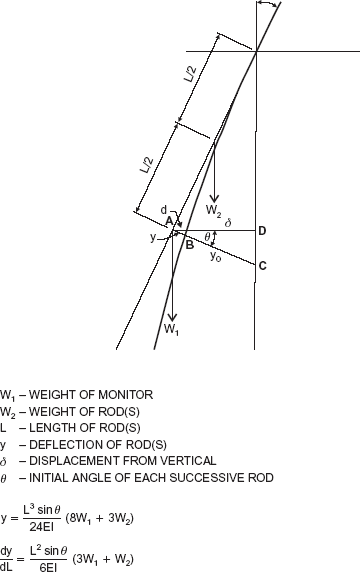
Jet-grout drill string deformation: W1, weight of monitor; W2, weight of rod(s); L, length of rod(s); y, deflection of rod(s); δ, displacement from vertical; ϕ, initial angle of each successive rod
Jet-grout drill string deformation: W1, weight of monitor; W2, weight of rod(s); L, length of rod(s); y, deflection of rod(s); δ, displacement from vertical; ϕ, initial angle of each successive rod
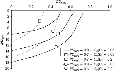
Cut-off thickness calculated by probabilistic analysis assuming SD(α) = 0·7° with a risk factor of 5%
Cut-off thickness calculated by probabilistic analysis assuming SD(α) = 0·7° with a risk factor of 5%
As a conclusion, the main point raised by the discusser is that some degree of uncertainty is unavoidable for vertical cut-offs to be made by jet grouting. However, such uncertainty can be governed by means of probabilistic design analyses, which can be extended and refined during construction with the aid of careful monitoring.
REFERENCES
APPENDIX: DEVIATION OF JET GROUT DRILL STRING FROM VERTICAL
Suppose it is intended to construct a jet-grouted column by a technique using enlargement of an open bore by pre-wash jets during the drilling or penetration phase of the process. Assume further that the drill rods on the rig have been set up incorrectly such that the initial slope is 1 horizontal to 250 vertical, and they are clamped rigidly on that alignment to a stable drill rig. As more rods are added to the string, if they were rigid also, their projected line would be as shown along OA in Figure 4.
However, the rods are not rigid, and as the string is extended it flexes and deforms as the weight of the monitor attached to its bottom end, W1, and its own self-weight W2 drag it towards the vertical. The amount of the deflection, y (= AB) is given by the equation for the deflection of a cantilever for each element of the weight resolved perpendicular to the last rod added
and the inclination of the bottom end of the rod string is
In these equations y = AB, L = OA (the cumulative length of the string), θ is the angle of the lower extremity of each rod to the vertical (initially of tangent 1 in 250), W1 is the weight of the monitor, W2 is the self-weight of the rods (= wl, where w is the weight per unit length of rod), E is the elastic (Young's) modulus of the rods, and I is their moment of inertia.
The deviation from vertical is represented by the length BC — y. BC may be taken as equal to AD because θ is small, so the horizontal deviation δ is effectively equivalent to BC — y.
The force driving the deformation is the combined weight W1 and W2 resolved perpendicular to the rods, or their undeformed projection beyond the lowest rod. Thus the angle θ diminishes (according to dy/dL) with the addition of each rod, and the lateral influence of the weights declines with increasing length. To trace the deformation the calculation has to be iterated for each rod. The equations eventually become invalid when a diminishing deviation is indicated, as the rods hang vertically from the depth at which the maximum deviation occurs. The equations are approximations, as the angle θ for W2 becomes slightly greater than that for W1 as more rods are added, but as θ is small the discrepancy is small and underestimates y: because y is subtracted from BC the calculated deviation δ is fractionally overestimated.
Properties of rods and drill string typical for jet grouting used for the calculated results quoted
Weights:
Jet monitor = 8·0 kg
then three rods 3 m long, 58·5 kg each
and 11 rods 2 m long, 39·0 kg each
Total weight of rods for 31 m length = (3 × 3 m) + (11 × 2m) = 31 m overall length of rods at 19·5 kg/m length
Weight of string:
31 m × 19·5 kg + 8 kg = 621·5 kg
Radial dimensions:
Diameters: monitor 150 mm
Rods: 88·9 mm o.d., 68·9 mm i.d.
Modulus of steel:
Young's (elastic) = 210 000 MPa
Moment of inertia = 1·894 × 10−6 m4

