Conveyor systems which can serve only specific source-destination pairs are generally very rigid and not easily adaptable to serve new routes for new routing demands. The present work offers a formulation and solution for controlling a grid-like conveying system which is designed to adaptively serve any demand for routing between a source-destination where routes can be reconfigured.
Highly configurable conveying systems are critical in sorting or automated storage facilities. In such facilities, various items need to be sent from arbitrary sources to arbitrary destinations. This work uses reverse breadth first search (BFS) to find and maintain all the alternative paths in a grid graph (not just the shortest ones) in order to support routing in the grid. This also provides a degree of fault tolerance so that the conveying system can continue operating using alternative paths. With this approach it is not needed to run it repeatedly for every package to be conveyed.
This search algorithm does not only find the shortest paths within the grid, but it can successfully highlight the dexterity in the grid and allow for the expression of reachability to be updated to eliminate all paths that contain failing nodes.
This work contributes a conveyor grid design consisting of an acyclic grid, the analysis, determination of paths using reverse BFS and the method for managing the routing while providing a degree of fault tolerance.
1. Introduction
Material handling and topology of the systems that perform a similar task have been discussed in many works by researchers. However, instead of the traditional long term production run of a standard product, modern manufacturing requires short production runs of various products (Kotze, 2016). Numerous works have dealt with creating high density grid systems which have storage capabilities so that material is temporarily stored on the grid and retrieved when needed. In this setting, researchers also handled such systems as puzzles (puzzle-based systems) that would lead to successful delivery of material when solved. Alahmad and Ishii (2021) summarized a few traditional methods that researchers use to solve puzzles. This included creating a game-tree (inverse method) which tracks the input node from the target node. This would guarantee finding the shortest path but can generate redundancy and local loops (especially with dexterous nodes and the presence of multi-directional nodes within proximity of each other). Another method is a path-finding algorithm that begins at the input node and considers all possible configurations until the target node is reached. This algorithm is the working principle of Dijkstra’s algorithm (Dijkstra, 1959). Dijkstra’s algorithm is able to find the shortest path from a given source node to every other node. It also has the ability to find the shortest paths for a specific destination node by terminating the search process once a short path to that destination has been identified. A few researchers have deployed this principle to reconfigure routing of flexible manufacturing systems. For instance, Windmann et al. (2019) used dynamic programming (i.e. Dijkstra’s algorithm) to compute the fastest route through the conveying system. While Chen et al. (2022) used an improved version of the algorithm to find the shortest path in an industrial workshop scenario.
Decentralized control conveyors have been increasingly used across industry. They allow for the packages to be rearranged within the system and later be retrieved at an assigned output point observing a predefined sequence (Fleischmann and Furmans, 2024). One of the drawbacks of high-density storage conveyor systems is the slowdown of throughput due to the complexity of the structure. Some works proposed methods to handle this situation, such as the GridHub system (Gue and Hao, 2016). Gue et al. (2012, 2014) used a high storage density system that considered carton sequencing and relied on puzzle-based movement to transfer packages across the grid. Krühn et al. (2013) considered the small scaled multidirectional cognitive conveyor that adapts to changing load situations, while Lieberoth-Ledan and Fottner (2018) proposed a model that utilizes buffer nodes within the conveyor system to fulfill certain arrival criteria. One of the drawbacks of decentralized conveyor systems is the potential of deadlocks. According to Tanenbaum (2007), a set of processes are said to be in deadlock when every process within that set is waiting for a resource to be released by another process within that set; this is known as “mutual exclusion”. There exist methods which handle deadlock prevention within decentralized controlled material flow systems and which are generally based on obtaining exclusive access to resources before a task is completed. In the context of conveying mechanisms, routes or route sections may be reserved before a transport task is initiated; an example is the work of Mayer and Furmans (2010).
In this work we present a conveying grid which balances relative simplicity, manageable control scheme, fault tolerance and is deadlock free. The focus of this work is strictly on providing a simplified method to track the reachability of target nodes from any input node on the grid using reverse level order traversal (reverse BFS). The objective is to find all the paths and maintain them in an efficient way in order to facilitate routing without having to recompute paths every time in real time. The concepts of decentralized control and high-density conveyor systems have not been considered in this work. Thus, no storage is assumed to exist at any of the grid nodes. In the following sections we describe the topology of the conveying system and a method for its analysis. Based on the analysis method, a control algorithm is described which governs its operation.
2. Methodology
2.1 System topology
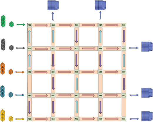
The system under consideration assumes the specific topology shown in Figure 1.
This proposed network resembles a centrally-controlled material handling and sorting system in industrial settings. The topology is a grid-like arrangement of nodes each of which is capable of conveying items received at one of its three sides (shown here as north/west/south) to one of its other sides (shown here as north/east/south). This assumes that packages are fed to the system from the left side to be conveyed to receivers on the right side. Each (internal) node of the grid functions as a right-angle transfer or as a straight-through transfer node moving a package received on one of its three ports to any one of its other ports. Essentially, an item can move on the same column it is currently in or pass to the column on the right, but it cannot go back to a column it has left already. The grid has a central controller with possible preset directions of nodes stored in a central processor and can be retrieved by each node. The major issues to be addressed then are, how do nodes decide what transfer to perform (straight-through or right-angle) and what are the properties of the overall system. This will be explained in more detail later in this work.
First, in order to avoid deadlocks, we opt for an architecture which is free of cycles, i.e. no package should be able to return to any internal node from which it has already passed before. The chosen architecture is shown in Figure 1 where the number of columns and rows can be arbitrary. It should be noted that the requirement is that the (directed) graph of the grid is acyclic and otherwise the specific vertical directions can be arbitrary as long as cycles are not introduced; the vertical directions shown in Figure 1 are chosen for illustration.
In this architecture, all the West-to-East transfers are allowed on all nodes on all rows. In addition, for each item to be transferred, each particular node needs only one other node to transfer its load to. In other words, for each transfer task each node needs only one other resource (node). Therefore, there can be no deadlocks which typically appear when various processing nodes wait cyclically for each other. A node like N22 (for example) trying to transfer a package to N23 may have to wait for a transfer from N13 to N23 to finish, but it will eventually get its turn.
Packages travel on a grid of conveyor nodes each of which has the ability to move packages which are in-coming from left to the right or up or down side of that node. Each of these conveying nodes operates independently of its neighbors but their local transfer directions must all be coordinated through the central controller to achieve the desired origin-to-destination routing. Available directions are labeled with arrows on each conveyor connecting two nodes. All possible paths are calculated offline (they can be calculated in quasi real-time as the computational time is relatively short).
2.2 Controlling the transfers
It is desirable that transfers from origin to destination use a minimal number of grid nodes, so that the shortest path is used. However, this may result in congestion for certain routes and may not be achievable especially when some nodes fail. So at least for reasons of fault tolerance, alternative routes besides the shortest path need to be considered in the controlling method.
The routing problem is formulated as a “reachability” problem in this work; the proposed method maintains information about the ways that a destination node is reachable from any other given node. Based on this formulation, the proposed method achieves effective routing which is able to adapt to conveyor faults while routes are still possible.
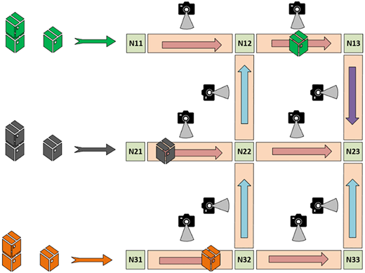
The grid is assumed to have a conveyor monitoring system of spatially installed scanning cameras on each conveyor segment to read the label on each package (such as a bar code or RFID). The scanner communicates the label information to the central controller which in turn identifies the package type, the direction at which it is arriving and determines the direction it should be routed to. Figure 2 below shows a subset of the grid with scanning cameras installed.
Then the paths which lead to the destination from the current node Nij are accessed; one of these paths is selected by the central controller and the information is relayed to the node at the end of the conveyor segment. This describes in short the transport decision made locally at node Nij in order to facilitate the desired routing. This assumes that the nodes of the grid have some limited computational ability, but only enough to store paths to destinations and make some simple determinations as it will be explained in the following sections.
Nodes that are bi-directional or tri-directional may use multi-directional conveyor rollers, which are widely used in industry today. These rollers allow the node to receive the package from multiple directions (i.e. TOP, LEFT or BOTTOM) and route it in different directions as well (i.e. UP, RIGHT or DOWN). These codes are included in Table 1 below.
Each node receives a signal in the form of an array that contains: code of the package (a,b,c,d or e) which represents the source of the package, the direction it is arriving at (TOP, LEFT or BOTTOM) and the central controller will determine the direction it is exiting at (UP, RIGHT or DOWN), as follows:
To better handle this data, the following coding is established:
For example, if node N22 is receiving package c from the BOTTOM and routing it to the RIGHT, then the array of commands it will receive will be [3,3,2]. This vector will be activated once the scanning camera on the conveyor segment connecting N32 and N22 detects a package.
2.3 Explanation of the algorithm
In trying to determine what routes lead from a node Norigin to a destination D, let us define the “reachability” set of D as the set RD of all the nodes of the grid from which D is reachable, i.e. RD is the set of all nodes Nij where a path exists from Nij to D. The RD set can be determined effectively using the simple observation that if a node Nij is in RD and Nij is reachable by another node Nxy, then Nxy also belongs to RD. Therefore, we can start from D and gradually expand to nodes from which D is reachable. The expansion should progress so that at every step the old RD is expanded with new nodes which are neighbors and can reach in a single move one of the nodes which are already in RD. In computing, this is known as a (recursive) breadth-first search (BFS) method for reverse order traversal.
Incidentally, this algorithm is the basis for Dijkstra’s shortest path algorithm, but BFS can also be used to compute the RD sets and consequently all the routing paths leading to any destination. While BFS is best suited for searches with uniform edge weights, a Dijkstra’s variant can be used with paths (graphs) with edges of arbitrary weights (Zhou and Hansen, 2006; Madkour et al., 2017). In a complex computer network or graph traversal, the computation time to complete either method can be used to establish a quantitative comparison between these methods (Zarembo and Kodors, 2015; Singhal and Kundra, 2014; Permana et al., 2018). Computational comparisons for search algorithms originate in computer communication networks or for traversing complex graphs. However, for a finite network (similar to a conveyor grid), such comparison cannot yield meaningful results.
More formally, the computation is performed as follows:
2.3.1 Reachability algorithm
# Compute the reachability sets for all the destination nodes
For each destination Dk:
RDk = {Dk} #initialize RDk to just the node Dk itself
While it is possible, repeat:
For each node Nij which is not already in RDk:
if Nij can directly reach a node Nxy currently in RDk:
RDk = RDk ∪ {Nij}
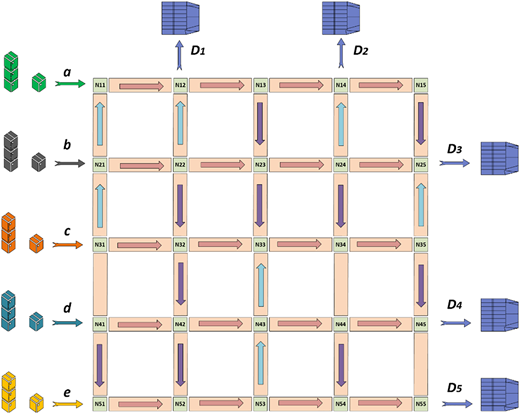
where the subscript k refers to the number of the destination node labeled in Figure 4 below.
At the end of this simple algorithm, RDk will contain all the nodes which can reach Dk by some route. Computationally, this algorithm typically has a O(n2) complexity, which means that the computational effort for it is proportional to the n2 of the number of nodes in the grid. That does not constitute an excessive computational cost for most industrial controllers.
The following is an expansion of this algorithm to obtain all the paths in Paths2Dk which lead to each destination Dk. Each path in Paths2Dk is represented as a string denoting a node sequence.
2.3.2 Routes algorithm
For each destination Dk:
RDk = {Dk} #initialize RDk to just the node Dk itself
Paths2Dk = {Dk} #initialize paths to Dk to just Dk
While it is possible, repeat:
For each node Nij which is not already in RDk:
if Nij can directly reach a node Nxy currently in RDk: {
RDk = RDk ∪ {Nij}
Paths2Dk = Nij* Nxy_Paths2Dk
}
where Nij* Nxy_Paths2Dk indicates a concatenation which prefixes Nij to each path in Paths2Dk which starts with node Nxy.
The resulting expression of reachability is the union of all individual paths that lead to the specific target node from all “reachable” input nodes. Besides being a focused and intentional method, it also highlights the dexterity in the grid as well as the shortest paths available. If one or more intermediate nodes fail, this method allows for the expression of reachability to be updated to eliminate all paths that pass through the failing node(s). Once all the valid routes from a source to a destination are identified, the focus will be on choosing a route to perform the transport as explained in the next section.
2.3.3 Reachability sets and fault tolerance
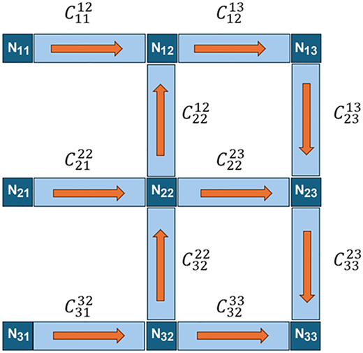
Consider the simple acyclic grid of Figure 3. Conveyor segments that connect between two nodes (single hop) are labeled as follows:
where i and j are the row and column of the node at the origin of the conveyor (Nij) and k and l are the row and column of the node at the end of the conveyor (Nkl). To better control each node from the central control unit, each node should receive a signal to route the package enroute to its final destination. Nodes that can move the package in different directions (i.e. UP and RIGHT) will need to decide which direction to activate by the time the package arrives at that node.
Assume N23 is the destination node in the grid shown in Figure 3. The following algebraic expression can be outlined:
Similar to Boolean operators, (+) is an OR and (*) is an AND.
Through the implementation of the proposed algorithm, the reachability set will continue to expand until no further nodes that lead to that destination can be identified. As follows:
The utility of this method is evident in the search domain generated. For example, the domain is not computationally expensive to calculate, it shows the shortest paths and it lists all possible paths in case the shortest path is not feasible (i.e. due to a failure in some nodes). For instance, assume that node N22 failed or is inactive and no packages can be moved through it. The resulting paths will be shortened by excluding any path that contains that node. That is, the paths to the destination node N23 will immediately be reduced to the following:
Due to the failure of node N22, source node b would not be able to reach the destination node. Thus, node b cannot be used to send packages to the destination node N23. In this case, the central controller will search for an alternative, such as switching the destination node to another one that can be reached by b or to feed the packages through a different input node (i.e. nodes N11 or N31).
The number of different paths which may need to be stored or checked is not of much concern because the lengths of the paths are bounded due to the acyclic requirement of the grid. If we assume R rows and C columns in the grid, then we note that since a transported item can only move to a column to its right (East), it will make a maximum of C hops in the horizontal direction. On any particular column, a package can make a maximum of R hops in a vertical direction along any particular column before moving to the next column and move R hops in the opposite vertical direction (worst case). So the worst case number of hops on any transport path from any source to any destination would be C-1+R*C; thus, no path would be longer that C(R+1). Also, with R options from where to leave each column and C columns to travel through, the max number of paths from any one source to any one destination would be of the order of RC.
2.4 Operating the conveying grid
A variety of control schemes can be used to operate the grid. These schemes would be a mix of centralized control and local controls at the nodes depending on how much computational power we wish to delegate to the individual nodes. A centralized control would compute the reachability sets (paths to destinations) for each node. With any specific scheme, a common action in case of a node failure is to invalidate the paths which contain the failed nodes.
One control scheme would be to delegate some of the processing to the individual nodes. In this case, the reachability sets would be computed centrally and then broadcasted to the nodes and each node would store its own. Each node should have adequate computing power to determine the local action for a package arriving at that node. Specifically, the package would only need to carry a label for its destination; the node would access its reachability set of paths for the intended destination and would select one. The selected route then determines the node to which the package should be passed on. The selection can be made with a variety of criteria such as shortest route, or route loads. It is possible to maintain dynamically updated statistics on route loads. In case of a node failure, all other nodes should be able to receive this status information and invalidate paths which contain the failed node. Incidentally, the same communication means used to broadcast status information can be used to facilitate the update of load statistics at the grid nodes or the grid links.
Another control scheme would be to retain these reachability sets at the centralized control. Packages to be conveyed would be tagged with individual item-codes (barcodes, QR, DataMatrix codes etc.). The central control would then broadcast to nodes – the specific local action which should be taken for each of the item-codes. This scheme would place minimal requirements for computing at each node. It would require an ability of nodes to receive instructions from central control as well as an ability of nodes to report successful completions of transfers locally at each node.
This work assumes the latter approach in which routes are calculated and local decision-making is broadcasted to all nodes to perform transfers locally. This approach allows the use of industrial controller systems commonly used in large-scale manufacturing plans, such as Distributed Control System (DCS). Thus, it can be integrated within the existing infrastructure with minimal customization.
3. Results
To illustrate the proposed algorithm and to test its functionality, a grid-network of five rows and five columns, shown in Figure 4 below, is used. The assumption for this illustration is that the flow can only be from left to right and up and down. A combination of five loading nodes (a through e) and five destination nodes (D1 through D5) are labeled to test the algorithm. Packages on nodes (a through e) travel to one of the arbitrary destination nodes (D1 through D5) according to the fulfillment order (i.e. as in the case of online retailers).
Each node is accessible from the top, left and bottom, respectively. Let represent the accessibility of a node Nij:
For instance, according to Figure 4, N23 can be reached from the top and left only. Thus, its accessibility vector is written as follows:
However, we note that the LEFT bit is always 1 with the choice of an architecture where a node can always pass an item to the node on it right (East) and so an actual representation of it is not necessary (it would suffice to represent and so ). Though, the representation used allows for the implementation on a grid where the accessibility from the left is restricted.
Following the same pattern, the accessibility matrix A for all the nodes as a matrix can be established as follows:
This information is essential to identify and expand the reachability set of each destination. For instance, the neighborhood reachability set (spatial reachability) of each node can then be established as shown in the following matrix R:
Given the grid-like topology of the system, for any node Nij, the node on its left is Nij-1, the node on its right is Nij+1, the node on its north would be Ni-1j and the node its south would be Ni+1j. Thus, A can be rewritten as:
The example network shows five different destinations D1 to D5. The implementation of the algorithm to determine the reachability of each destination will generate five sets of reachability domains. Subsequently the Paths2D1 … Paths2D5 can be computed (per the routes algorithm described earlier). Each represents a mix of short paths and other alternative (longer) paths. For instance, following the routes algorithm explained above, the reachability set for destination 2 (D2) at node N14 can be established as follows:
Notice that both loading stations d and e cannot reach the destination node N41 and thus they do not appear in the reachability set for D2.
4. Discussion
The BFS is a fundamental algorithm used to determine paths in general graphs. Reverse BFS is used to determine paths which reach destinations. The proposed method uses path information to determine reachability and produce routing decisions assuming that computing power at the various intermediate nodes is limited. A method known from computer networking as dynamic routing maintains routing tables at each node which are constantly (dynamically) updated with traffic load information. To perform this sort of updating, compute power is required at the nodes as well as frequent communications about traffic load at various links. This work is premised on the fact that conveyor networks usually have a topology that is quite static (in the sense that the topology of conveyor links does not change often) and they are not as dense as computer networks. Therefore, a scheme that requires constant dynamic updating, constant communication exchange and substantial compute power at the nodes (which are likely to be controlled by simpler/lighter IoT devices) will not be practical in the context of a conveyor system.
The destination sets contain sequences of paths separated by OR operators (+) that address all nodes that a package would pass by to reach its destination. The nodes within a sequence can appear in any order since they are all equally important to deliver the package to its destination. A failure in any node in the sequence will render that sequence invalid since they are logically ANDed together. The proposed scheme can be integrated within the existing infrastructure of most manufacturing plants with large-scale and sophisticated processes. DCS uses a set of automation equipment and protocols interconnected together to manage different machines and processes commonly present in manufacturing plants.
Even in the case of smaller-scale implementation of the scheme, a programmable logic controller (PLC) can serve as a central-controller to handle computation and decision-making. PLCs are the traditional and standard method for controlling industrial processes. The suggested grid uses a simple monitoring system that consists of industrial scanners (labeled with an identifying tag known to the controller) and interfaced with the DCS or PLC.
The resulting destination sets can successfully highlight the dexterity in the grid as well as the shortest paths available. This method allows for the expression of reachability to be updated to eliminate all paths that contain failing nodes.
5. Conclusion
This work aimed to address the problem of routing packages in an industrial setting from various origins to various destinations using a configurable conveyor system. The goal was to standardize the architecture to a grid-like system, avoid potential deadlocks (thus the acyclic requirement), retain a degree of fault tolerance and produce an algorithm for its analysis and operation. The operation allows either fully centralized control or a balance between central supervision and local control.
The use of recursive BSF allows for organic elimination of nodes that are not reachable by the destination points, as the search progresses in a reverse direction and only nodes that are traceable from the destinations are searched. Thus, it optimizes the computational cost of the process. The importance of this optimization is evident as the network is scaled up. In addition, this method allows for the computation and maintenance of the routing information which is resilient in the presence of faults and can continue to be used without major re-computing of paths.
Since the focus of this work is strictly on providing a simplified method to track reachability of target nodes from any input node on the grid, the concepts of decentralized control and high-density conveyor systems have not been considered. Thus, no storage is assumed to exist at any of the grid nodes. Future possible extensions of this work can consider the effect of decentralization and high-density conveyor systems to achieve a more comprehensive model.