


This study explores the mechanical behavior of cranial implant unit cells designed to offer tunable compliance characteristics while maintaining constant mass and geometric constraints. The goal is to demonstrate that postoperative cranial sensitivity can be addressed by locally adjusting the stiffness of implantable structures at the cellular level.
Two distinct implant unit cell configurations were developed using a deformation-driven optimization approach. Although their geometry and mass were identical, internal stiffness distributions were altered by changing cross-sectional design bounds in the optimization algorithm. Experimental validation was carried out through compressive loading tests, and force–displacement data were analyzed to assess the mechanical response of each design.
The results showed that it is possible to significantly alter the elastic behavior of unit cells by adjusting internal architecture without changing overall volume or material. The M2 model, in particular, exhibited a broader low-stiffness plateau in its force–displacement curve, suggesting enhanced suitability for sensitive cranial zones. The degree and spatial extent of compliance could be effectively controlled through simple modifications of optimization parameters.
Unlike conventional cranial implant studies that focus on full-implant geometry, this work introduces a scalable, unit-cell-based approach where local mechanical performance can be tuned through structural optimization. The methodology supports the integration of sensitivity-specific zones within future implant assemblies using pre-validated, stiffness-controlled cellular modules.
1. Introduction
Cranial reconstruction has evolved significantly with the introduction of advanced materials and manufacturing technologies aimed at restoring skull integrity following trauma, surgical resection, or congenital malformation. Traditional reconstruction using autologous bone or titanium mesh remains widely used; however, limitations related to mechanical mismatch, infection, and long-term integration have encouraged the search for alternatives (Han et al., 2021).
To address these limitations, studies have proposed various synthetic materials and implant configurations. One such study developed multilayer micro-lattice biomaterials with compressive strengths comparable to native bone tissue, demonstrating favorable deformation behavior under quasi-static loading conditions (Zhao et al., 2022). In line with this, PEEK (polyetheretherketone) has emerged as a promising implant material due to its excellent biocompatibility and mechanical properties resembling cortical bone Zhao et al., 2022; Zhang et al., 2023a).
Similarly, porous PEEK implants designed to mimic the natural cranial architecture have been shown to enhance tissue regeneration while maintaining mechanical integrity (Zhang et al., 2023b).
Shash (2024) further explored alternative materials such as alumina, zirconia, and reinforced PMMA, revealing their effectiveness in reducing skull and brain stress under impact loads.
Efforts to customize implants for individual cranial topographies continue to expand. Singh et al. (2023) proposed a 3D printing-based design pipeline that allows symmetric and asymmetric implant generation using CT data. Their finite element validation under lateral impact conditions confirmed the viability of the produced geometries.
A particularly promising direction involves magnesium-based biodegradable implants. Zhang et al. (2024) demonstrated how magnesium alloys can support bone repair through osteoimmunological modulation, offering both mechanical support and biological signaling.
In addition to material innovation, the integration of biomechanical simulation into the implant design process has significantly enhanced the predictive capacity of cranioplasty planning. Li et al. (2023), in their overview of the Auto Implant 2021 challenge, emphasized the role of automation and data-driven design in accelerating the clinical workflow. These computational pipelines, while highly effective in geometric restoration, often fall short in evaluating biomechanical safety under physiological loading.
Pioneering automatic restoration frameworks such as those described by Li et al. (2021) apply deep learning to cranial CT datasets, enabling high-fidelity shape completion. These models show potential for immediate application in trauma cases where time-efficient reconstruction is critical. Complementary to this, Kesornsri et al. (2024) introduced a classification-based design approach (CraNeXt), combining skull segmentation with deep neural networks for defect-specific implant generation.
The incorporation of artificial intelligence in medical image analysis has also contributed to mesh quality improvement and defect boundary detection. Liu et al. (2024) applied conditional diffusion-based signed distance field methods to generate high-resolution and mechanically consistent cranial implant geometries. Their approach enhances precision in skull shape completion while reducing post-processing time.
Fabrication techniques remain equally important. Material extrusion-based additive manufacturing of PEEK implants has been studied extensively, with parameters such as build orientation, airflow, and cooling rates shown to influence mechanical behavior and surface finish (Petersmann et al., 2023). Similarly, Kennedy et al. (2024) reviewed the evolution of 3D printing techniques in healthcare, emphasizing the transformation of PEEK from a niche polymer to a mainstream implant material due to its adaptability and strength.
From a biomechanical standpoint, Santos et al. (2022) evaluated the structural performance of large cranial implants using finite element modeling. Their findings highlighted the effect of fixture placement and screw configurations on global deformation and local stress accumulation, confirming that design optimization at the fixation level is as critical as material selection.
Likewise, Kim et al. (2023) explored asymmetrical cranial patches, incorporating fixation components directly into the design. Using patient-specific CT datasets, the implants were tested under simulated intracranial pressure and point loads. The results revealed how geometric tuning at the boundary significantly reduces peak stresses and improves distribution.
Moncayo-Matute et al. (2022) investigated neurocranial protection through PMMA-based implants using FEM simulations. They quantified critical deflection and von Mises stress concentrations under multiple load cases, providing evidence for the structural adequacy of customized PMMA implants.
Further comparative studies have shown that properly reinforced PMMA implants can approach the performance of more expensive materials like PEEK. In a follow-up investigation, Moncayo-Matute et al. (2023a) simulated 3D-printed implants with both PMMA and PEEK, observing minimal performance gaps under comparable stress states. These findings suggest a cost-effective pathway for cranial implant production in resource-limited settings.
The integration of reverse engineering and patient-specific modeling techniques continues to shape the future of implant customization. Moncayo-Matute et al. (2023b) conducted a mechanical comparative study using finite element analysis to evaluate patient-specific implants fabricated from PMMA and PEEK. Their results confirmed that both materials, when carefully shaped and anchored, could maintain cranial integrity under simulated trauma conditions.
A related study by Moncayo-Matute et al. (2023c) explored mechanical analysis of implants specifically designed for neurocranial protection. Their FEM simulations revealed how design factors such as curvature, thickness, and edge fillets significantly influence maximum principal stress locations, particularly in thinner cranial regions.
Artificial intelligence-enhanced pipelines for cranial reconstruction were further advanced by Juneja et al. (2025), who introduced a comprehensive framework that combined CT preprocessing, deep-learning-based reconstruction (CRIGNet), and biomechanical assessment. Their model outperformed CAD-based workflows in anatomical fidelity and reduced production time from hours to seconds.
In terms of material choice, Zhang et al. (2023a, b) designed integrated porous PEEK implants and tested them in vivo for defect repair. The porous microarchitecture closely matched the natural trabecular pattern of cranial bone, enabling rapid cell infiltration and scaffold integration. These implants demonstrated full healing with host bone within six months.
Han et al. (2021) contributed clinical insights from 19 cases of large cranial defect repair using a two-stage protocol: first with free myocutaneous flap coverage, followed by implant reinsertion. Their long-term follow-up showed complete flap survival and no cranioplasty failures, emphasizing the value of staged reconstruction in infection-prone scenarios.
Zhang et al. (2024) presented a magnesium–zinc alloy-based biodegradable implant that promoted skull repair while modulating the immune environment. Their study is among the first to demonstrate M2 macrophage induction and bone marrow stem cell osteogenesis via material-based immune signaling.
In pediatric and growing skulls, integrated design must consider not only strength but also adaptability. Zhang et al. (2023b) explored PEEK implant strategies specifically for growing crania. The porous architecture allowed dynamic shape accommodation and reduced the need for surgical revision during skeletal development.
From a materials science perspective, Qi et al. (2024) evaluated sandwich-structured PEEK implants fabricated via additive manufacturing, demonstrating how inner dense–porous–dense layering enhances osseointegration. From a materials science perspective, Holtzhausen et al. (2024) demonstrated the successful additive manufacturing of calcium phosphate cements (CPC) for large skull defects. The printed CPC implants showed controlled porosity and matched the compressive strength range of native bone, supporting their use in temporary or semi-permanent reconstructions.
Lastly, Resmi et al. (2024) utilized transformer-based neural networks to automatically complete defective skull shapes. Their model achieved superior Dice scores compared to 3D U-Net variants, highlighting the potential of vision transformers in anatomical reconstruction tasks.
The clinical significance of cranial reconstruction extends beyond aesthetics and protection. Schievink et al. (2024) described a series of patients with frontotemporal dementia sagging brain syndrome in whom structural symptoms improved following revision cranioplasty. This underscores the neurological role of cranial integrity and motivates greater mechanical attention in implant design.
Jindal et al. (2023a, b) conducted a comprehensive comparative analysis of cranial implants and fixture designs using finite element simulations. They evaluated combinations of materials such as autologous bone, PMMA, PEEK, and titanium alloy, showing that polyether-ether-ketone exhibited significantly reduced von Mises stress under equivalent loads and that square-shaped fixtures offered superior mechanical dispersion.
In practical manufacturing workflows, Bogu et al. (2017) proposed a reverse engineering protocol for skull implants applicable to both midline and lateral defects. Their model, developed in ANSYS and validated with CT-based anatomical meshes, demonstrated the effect of fixation point quantity and placement on implant deflection and local stress.
Further clinical evaluation of 3D-printed PEEK implants was carried out by Elnaggar et al. (2025), who tracked surgical and post-operative outcomes in a case series. They found improved esthetic contour, minimal inflammatory response, and good osseointegration across diverse cranial defect morphologies.
Finally, Cho et al. (2015) presented early clinical results from the use of custom 3D-printed porous titanium implants in large cranial defect reconstructions. The implants, designed from CT data and manufactured via electron beam melting, showed perfect anatomical fit, successful osseointegration, and zero complications over follow-up.
1.1 Purpose and technical context
This study focuses on the mechanical characterization of custom-designed cranial implant unit cells through experimental validation. The structures evaluated here were developed using a computational optimization pipeline based on pre-existing code frameworks. While the design phase was algorithmically supported, all physical assessments were conducted through laboratory testing to determine the force–displacement behavior of each configuration.
The aim is to demonstrate that it is possible to tune the mechanical response of implantable unit cells without altering their mass or geometric boundaries. Specifically, variations in compliance were achieved by adjusting internal cross-sectional distributions while maintaining constant overall volume. These differences were confirmed through compressive testing, revealing that M2 model exhibited broader elastic response regions than M1 model.
The mechanical contrast between these configurations suggests that implant sensitivity can be strategically managed at the cellular scale. By associating specific unit types with target anatomical regions, it becomes feasible to spatially control stiffness based on patient-specific postoperative sensitivity requirements.
All results presented in this study originate from physical testing of fabricated structures. No full implant assemblies were produced; instead, the emphasis was placed on verifying that the mechanical behavior of these elementary structures could be tuned and validated experimentally using predefined design scripts.
1.2 Method overview: compliance-tuned unit cell optimization
The core aim is to design cranial implant unit cells that have tunable mechanical compliance—in other words, cells that can be made stiffer or more flexible—without changing their external geometry or total mass. This tunability enables surgeons or engineers to adapt implants to regions of the skull that are more or less sensitive, improving patient outcomes after surgery.
1.2.1 Key concepts
Unit Cell: A small, modular building block used to form larger implant structures.
Compliance: A measure of how much a structure deforms under a given load. Higher compliance means the structure is more flexible.
Optimization: The process of adjusting the internal geometry of the unit cell to achieve the desired mechanical behavior.
To a better understanding step by step overview as follows:
Starting Geometry and Constraints
Each unit cell is defined as a cube of fixed size and mass.
Internally, the structure is represented as a series of 1D beam segments arranged in a linear chain.
These beams can have different cross-sectional areas but must collectively preserve the total mass and external dimensions.
Compliance Optimization
The goal is to minimize the total structural compliance, making the unit stiffer or more flexible depending on design parameters.
An optimization algorithm is applied that adjusts the cross-sectional areas of the beams within defined bounds:
- –
M1: More uniform cross-section limits, producing balanced stiffness.
- –
M2: Wider range of possible areas, allowing the algorithm to create localized “soft spots” or “stiff zones.”
- –
Mathematical Modeling
The beams are modeled using classical beam theory, combining both axial deformation and bending.
The local deflection δi\delta_iδi of each segment is calculated based on the applied force and the segment’s stiffness.
The total compliance is computed and used as the objective function in the optimization problem.
Mass Constraint Enforcement
The total mass is kept constant during optimization by adjusting beam areas inversely to their stiffness.
This ensures that mechanical differences arise purely from internal redistribution, not from changes in size or material usage.
Structural Smoothing
To ensure that the unit cells can connect seamlessly in a larger implant, adjacency constraints are added.
These limit abrupt changes in stiffness between neighboring beams, maintaining mechanical continuity.
Output and Fabrication
The final optimized geometry is exported as a set of cross-sectional area values and nodal coordinates.
These are used to generate 3D models (via GMSH scripts) and fabricate the unit cells for physical testing.
Compression tests are then performed to validate the mechanical behavior predicted by the simulations.
1.2.2 Design Variants: M1 vs. M2
M1: Optimized with tighter area bounds. Leads to more evenly distributed stiffness—suitable for areas needing uniform load sharing.
M2: Optimized with relaxed bounds. Results in highly localized compliant zones—ideal for sensitive cranial regions.
2. Methodology
This study presents a deformation-driven optimization framework to tailor the mechanical compliance of cranial implant unit cells. The goal is to achieve distinct mechanical behaviors through internal structural redistribution, while strictly preserving the external geometry and mass of each unit.
2.1 Concept and design objectives
Each unit cell is modeled as a cubic structure with constant dimensions and material volume. The interior is discretized into a series of one-dimensional (1D) beam segments aligned along a central axis. These beams serve as simplified representations of load-bearing paths within the unit cell. The design objective is to adjust the cross-sectional areas of these beam segments to obtain specific mechanical properties—either uniformly stiff or locally compliant—without altering the external shape or mass.
Two design variants are considered:
Model M1: Cross-sectional areas are constrained within narrow bounds, leading to a relatively uniform stiffness distribution.
Model M2: Wider bounds allow more aggressive internal redistribution, creating localized zones of compliance suitable for sensitive cranial regions.
2.2 Compliance optimization framework
The optimization problem minimizes the total mechanical compliance of the unit cell, defined as the work done by external forces during deformation. Each beam segment’s deflection is computed by combining axial elongation and bending effects using classical beam theory.
The local deflection at segment was defined as:
where:
Vi = shear force at segment i,
Mi = bending moment at segment i,
E = Young′s modulus
Ii = area moment of inertia related to cross-sectional area Ai via:
δinit,i=initial deformation contribution from distributed loading.
The total cell compliance was minimized:
while preserving overall mass and geometric constraints.
2.3 Optimization parameters: M1 vs. M2
Optimization was performed under different boundary conditions for M1 and M2 cells.
M1 Model Optimization Parameters:
Lower Bound:
Upper Bound:
M2 Model Optimization Parameters:
Lower Bound:
Upper Bound:
Initial Guess:
Thus, the M2 optimization was designed to restrict the feasible design space, producing finer control over local stiffness variations and more localized compliant zones.
Both optimizations enforced mass conservation:
ensuring that mechanical changes were achieved without altering the external envelope or density of the structure.
2.4 Loading conditions and force modeling
Simulated compressive loading is applied to evaluate mechanical behavior. The force applied to each segment F is derived from the global deformation pattern and distributed symmetrically across the structure:
and distributed symmetrically across segments:
where is the maximum moment derived from bending load simulations.
2.5 Structural continuity and adjacency smoothing
Although full implant assembly was not conducted at this stage, mechanical continuity principles were applied:
Face-sharing adjacency matrices were used,
Local stiffness gradients between neighboring cells were constrained to avoid abrupt transitions:
where is a small threshold ensuring smooth mechanical integration.
2.6 Geometry and export
The optimized cross-sectional properties and nodal displacements were exported via:
Mcomma.txt (cross-sectional data),
Ncomma.txt (nodal data).
Custom GMSH scripting (finalescript.geo) automatically constructed meshed models for further visualization and mechanical validation.
Thus, the methodology successfully demonstrates that selective compliance tailoring is achievable through parameter-controlled optimization at the unit-cell level, paving the way for future sensitivity-managed cranial implants.
The optimization algorithm is depicted in Figure 1 step by step.
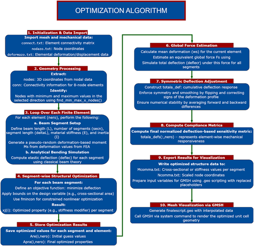
Stepwise schematic of the deformation-driven compliance optimization algorithm used for unit-cell design. The process includes input parameter selection (geometry, bounds, and mass constraint), beam discretization, stiffness matrix formulation, compliance minimization, and export of optimized cross-sections for fabrication and analysis. Source: Authors’ own creation
Stepwise schematic of the deformation-driven compliance optimization algorithm used for unit-cell design. The process includes input parameter selection (geometry, bounds, and mass constraint), beam discretization, stiffness matrix formulation, compliance minimization, and export of optimized cross-sections for fabrication and analysis. Source: Authors’ own creation
3. Results
This section presents the mechanical evaluation of the two optimized unit-cell designs—M1 and M2—under controlled compressive loading. Results include comparisons of geometry, experimental setup, force–displacement behavior, and deformation profiles.
3.1 Geometric consistency and internal structure
Both M1 and M2 unit cells were fabricated with identical external dimensions and material volume, in accordance with the fixed mass constraint used during optimization (Figure 2). Each unit cell forms a cube with internal variations dictated solely by optimization parameters.
M1 Design: Exhibits relatively uniform internal segment areas, resulting in balanced mechanical stiffness across the structure.
M2 Design: Shows pronounced variation in internal cross-sections, producing localized compliant zones within the same global volume.
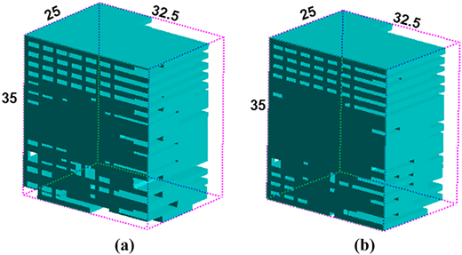
Geometrical representation and approximate dimensions of the (a) M1 and (b) M2 unit cells. Source: Authors’ own creation
Geometrical representation and approximate dimensions of the (a) M1 and (b) M2 unit cells. Source: Authors’ own creation
3.2 Experimental setup for mechanical testing
Both unit-cell configurations were subjected to quasi-static compression tests to validate the simulated mechanical behavior.
Each cell was vertically placed between two rigid steel plates.
A displacement-controlled load was applied from the top, while the base was fixed.
The tests were conducted at low strain rates to maintain quasi-static conditions and ensure alignment with the simulation assumptions.
The setup is depicted in Figure 3.
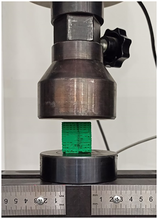
Experimental setup used for force–displacement evaluation. Source: Authors’ own creation
Experimental setup used for force–displacement evaluation. Source: Authors’ own creation
3.3 Force–displacement behavior
The mechanical response of the cells under load was evaluated through force–displacement curves, as shown in Figure 4.
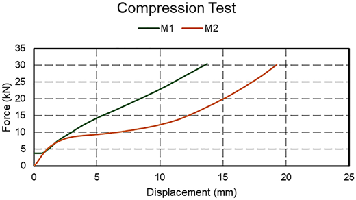
Force–displacement curves for M1 and M2 models under quasi-static compressive loading. Source: Authors’ own creation
Force–displacement curves for M1 and M2 models under quasi-static compressive loading. Source: Authors’ own creation
Key observations include:
Stiffness Differentiation: The initial stiffness of M2 is approximately 1.6 × higher than M1.
Elastic Plateau: M2 demonstrates a broader horizontal region in its curve, indicating greater elastic deformation before load transfer intensifies.
Tunable Compliance: The difference in behavior confirms that internal design alone can drive substantial compliance tuning, even under fixed external constraints.
These results support the feasibility of sensitivity management by embedding locally tailored unit cells within future cranial implants.
3.4 Deformation mode analysis
Deformation modes under load were visually examined to understand the structural behavior of each design (Figure 5).
M1 Units: Show distributed bending with relatively uniform strain spread across segments, indicative of isotropic mechanical behavior.
M2 Units: Localize deformation around compliant segments, with stiffer regions remaining largely undeformed. This targeted compliance aligns with the design intention of managing stress near sensitive zones.
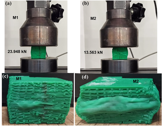
Deformation profiles of M1 (a) at 23.948 kN and (b) at 30 kN as the final and M2 (c) at 13.563 kN, (d) at 30 kN as the final, units under compressive loading, illustrating structural response differences. Source: Authors’ own creation
Deformation profiles of M1 (a) at 23.948 kN and (b) at 30 kN as the final and M2 (c) at 13.563 kN, (d) at 30 kN as the final, units under compressive loading, illustrating structural response differences. Source: Authors’ own creation
These observations are consistent with the cross-sectional area distributions generated during optimization and further validate the design strategy.
4. Discussion
The experimental and computational results demonstrate the effectiveness of the proposed optimization framework in tailoring the mechanical compliance of cranial implant unit cells. Importantly, the methodology enables precise internal tuning of stiffness profiles without altering the unit cell’s overall geometry or mass—a key requirement for modular integration into patient-specific implants.
4.1 Interpretation of mechanical behavior
The comparison between M1 and M2 models clearly illustrates how minor parameter adjustments in the optimization process result in significant differences in mechanical response:
The M2 model, optimized with wider cross-sectional bounds, exhibits broader compliant regions and larger elastic deformations under similar loading conditions.
The M1 model shows uniform stiffness, making it better suited for areas requiring consistent structural support.
The horizontal plateau in the M2 force–displacement curve indicates a region of lower stiffness, which can serve to buffer initial low-magnitude forces during postoperative healing. This highlights the second-level control afforded by the optimization—namely, the ability to adjust not only the presence but also the extent of compliant regions.
4.2 Implications for sensitivity management
Postoperative sensitivity, often caused by stiffness mismatches between the implant and healing bone, can lead to discomfort or chronic pain. The proposed design strategy directly addresses this issue by allowing:
Localized softening of implant subregions near nerves or high-sensitivity zones
Progressive load sharing as the cranial tissue heals
Reduction of abrupt mechanical transitions within the implant structure
Such functionality is critical for improving long-term patient comfort and functional integration, particularly in anatomically irregular or trauma-affected regions.
4.3 Design modularity and scalability
By working at the unit-cell level, the method supports future modular implant design:
Specific unit types (e.g. M1 or M2) can be strategically embedded into full implant geometries based on anatomical and sensitivity maps.
Prevalidated unit behaviors reduce the need for full-scale simulations for every design iteration.
This approach offers a scalable pathway for developing personalized implants, accelerating design cycles and reducing production time.
4.4 Limitations
While promising, the study has several limitations that should be addressed in future work:
Simplified Geometry: The unit cells are modeled as linear chains of beam segments, which may not capture complex 3D deformation modes found in real anatomical structures.
Quasi-Static Loading: The mechanical tests only considered static compression; dynamic loading conditions (e.g. impact or vibration) were not evaluated.
Isolated Unit Testing: The study focuses on individual cells; full implant assemblies and their long-range mechanical interactions were not assessed.
Biological Factors: The framework does not yet account for osseointegration, biological degradation, or long-term biocompatibility under in vivo conditions.
Addressing these issues will be essential to fully translate the method into clinical application.
5. Conclusion
This study introduces a compliance-driven structural optimization approach for cranial implant unit cells that enables targeted mechanical tuning while preserving mass and geometry. Two design variants, M1 and M2, were developed and experimentally validated under compressive loading.
The results demonstrate that:
Mechanical behavior can be effectively tuned by adjusting internal cross-sectional distributions, without altering external shape or volume.
The M2 model, optimized with relaxed cross-sectional bounds, exhibited a broader compliant plateau and greater flexibility—characteristics advantageous for managing postoperative cranial sensitivity.
The method enables control over both the presence and extent of compliant zones, supporting anatomically tailored stiffness adaptation.
These findings establish a strong foundation for integrating compliance-optimized unit cells into larger cranial implant systems. Future work will focus on:
Embedding these validated unit cells into full implant geometries,
Simulating their behavior under dynamic and multi-axial loads,
Exploring patient-specific design pipelines supported by medical imaging and AI-based anatomical mapping.
Overall, the approach offers a scalable, modular framework for developing next-generation implants that prioritize both structural integrity and patient comfort through localized sensitivity control.

