The authors are commended for their in-depth investigation for formulating an iterative procedure for design of deep beams with web openings partially interrupting the diagonal struts. The following observations are made for consideration by the authors.
(a) Service openings in a deep beam should preferably be located near the mid-span and limited in extent not to interfere with the elements of the best-fit strut-and-tie configuration representing the force paths in the particular deep beam. As mentioned by the authors, for simply supported deep beams with two-point loading, the opening must be trapezoidal in shape as the profile of the strut-and-tie model in such a case is trapezoidal. In general, if an opening does not encroach into the elements of the model, the deep beam can be analysed as a solid member as if the opening were non-existent. But the important issue here is how to decide whether the opening interferes with the bottle-shaped diagonal strut of the strut-and-tie model. Even though the least width of the bottle-shaped strut, which is obtained at the node-strut interface, is considered for calculation purposes, intuition suggests that the load-carrying efficiency of a bottle-shaped strut (e.g. strut-BC in Figure 9) is bound to be reduced if the bulb is interfered with by the web opening.
(b) The authors have formulated an iterative procedure applicable when the opening interrupts the axis of the diagonal strut at its bottom corner. If the opening were to interfere at the top as well as the bottom corners, the diagonal strut might have a second turning point near the top corner of the opening, which would necessitate a tie running above the top edge of the trapezoidal opening for equilibrium of forces at the upper bend. Furthermore, in the case of openings where tie-B is located farther away from tie-A, the reinforcement in tie-A may not be able to furnish the required tensile strength to tie-B.
(c) Recently Tan23 and Eun et al.25 have proposed new strut-and-tie modelling based methods for designing pierced deep beams where a pair of openings cut off the diagonal struts right at the centre, interrupting the upper as well as the lower force paths. The present paper gives a simple model suitable for trapezoidal opening that interrupts only the lower force path of the diagonal strut. It is felt that considering many possibilities in the number, shape, size and location of opening(s), a general strut-and-tie modelling based design approach is needed for the practicing engineers.
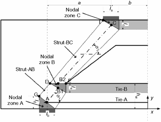
(d) The discussers have some doubt whether hAB1 and hB2C used in equations (12) and (13) respectively are the horizontal distances between A and B1 and B2 and C respectively, Figure 9. Similarly, in step 1 of the overall procedure, it is not clear which figure is being referred to with respect to the inequality lEF ≤ lJF.
Authors' reply
The authors offer the following response to the contributors.
(a) Yes. As mentioned in the paper, ‘Generally, the flexural cracks were the first to form in deep beams with web openings and the critical diagonal cracks are the main cause of failure, if the size of web opening does not interpose the force transferring path or reduce the strut width. In this case, the ultimate strength of deep beams with trapezoidal web opening is comparable with that of a solid beam.' However, ‘If the hole size is so large that it reduces the strut width, the failure mode changes from shear to localized failure of concrete at the hole corner.' In this case, the capacity of an additional nodal zone B will be checked in the proposed approach.
(b) Agree. More tests and research work can be done in the future to investigate the failure mode and ultimate load for deep beams with a web opening that: (i) interrupts the axis of the diagonal strut at both its bottom and top corner; and/or (ii) is located farther away from the longitudinal reinforcement. (In this case, the web reinforcement may be the critical variable governing the deep beam's capacity.)
A more general STM approach may be proposed as per the investigation.
(c) Yes. We agree with your comments that STM-based design approach is suitable for practicing engineers.
(d) hAB1 is the horizontal distance between A and B1; hB2C is the horizontal distance between B2 and C. Figure 9 should be referred to with respect to the lEF ≤ lJF, which was amended as per the Editor's requirement. The more informative figure is shown above.