This is an interesting paper introducing experimental and theoretical analyses of failure modes of four reinforced concrete continuous deep beams.
In addition to the study by Rogowsky et al.6 quoted by Dr Subedi as apparently the only information available on reinforced concrete continuous deep beams, other research had previously been published in this area.8–12 In particular, the discussers carried out some research on continuous deep beams. Two papers were published, one of them presenting a computational analysis of the beam modes of failure,8 and the other covering the experimental aspect of the work.9 The experimental work9 included testing of eight reinforced concrete continuous deep beams to failure. The main parameters studied were the shear span to depth ratio, arrangement of web reinforcement and amount of main longitudinal reinforcement. In fact, the geometrical dimensions and reinforcement arrangements of the two beams 2CB3 and 2CB4 tested by the author are very close to those of the two beams CDB1 and CDB5 in our tests. The following behaviour was observed during our tests and also supported by Dr. Subedi's test results.
The two span reinforced concrete deep beams generally fail due to major diagonal cracks on either side of the central support between the edges of the load and central support plates, often with one of these cracks opening wide and breaking symmetry at failure.
Reducing the main longitudinal top and bottom reinforcement may well not provoke other mechanisms, and produces only minor reduction of the beam capacity (compare strength of beams 2CB3 and 2CB4 of Dr Subedi's test specimens, and CDB2 and CDB5 of our test specimens).
In the computational analysis presented by the discussers,8 two mechanisms of failure were studied: the first mechanism is similar to the symmetrical mechanism studied by the author (mechanism A: combined rotation and translation mechanism), and the other is a pure translation mechanism (mechanism B). The theoretical results were compared against 20 beams (8 beams tested by us9 and 12 tested by Rogowsky et al.6) and good agreement was obtained. The main difference in the derivation of the failure load for the symmetrical mechanism presented by the author and that presented by the discussers is that the author used the equilibrium of the blocks at failure with various methods of predicting forces developing along failure surface, while we used the energy approach using upper bound theorem of plasticity theory and modified Coulomb failure criteria.
The two mechanisms presented in Reference 8 will be used here to predict the collapse loads of Dr Subedi's test specimens. Table 5 gives the non-dimensional failure load λ (= P/bhf′c, where P is the failure load on each span, b and h are the beam width and depth respectively, and f′c is the cylinder compressive strength = 0·85 cube compressive strength fcu) obtained from equation (10) (mechanism A) and equation (19) (mechanism B) given in Reference 8. The effectiveness factor of concrete used is the best mean value (v = 0·28) and the position of the instantaneous centre is assumed at the level of the top reinforcement as discussed in the paper.8 The governing mechanism, predicting lower capacity, and the critical collapse load λc are also given in Table 5. The mechanism of failure for the three beams 1CB2, 2CB3 and 2CB4 is successfully predicted by the computational analysis to be the rotational mechanism as observed in experiments. For beam 1CB1, mechanism B governs the failure. Comparison between the non-dimensional predicted failure load λc and the experimental failure load λm is shown in Table 5. The computational predictions obtained for beams 1CB2, 2CB3 and 2CB4 are in good agreement with the experimental failure loads. The load capacity predicted for beam 1CB1 is conservative but as good as Subedi's method.
Comparison between computed and experimental failure loads of beams tested by Dr Subedi
| Test specimens | Non-dimensional failure load, λ, from | Governing mechanism | Critical collapse load, λ*c | λ**m | λm/λc | |
|---|---|---|---|---|---|---|
| Mechanism A | Mechanism B | |||||
| 1CB1 | 0·268 | 0·239 | B | 0·239 | 0·344 | 1·440 |
| 1CB2 | 0·177 | 0·197 | A | 0·177 | 0·187 | 1·058 |
| 2CB3 | 0·232 | 0·289 | A | 0·232 | 0·249 | 1·073 |
| 2CB4 | 0·232 | 0·289 | A | 0·232 | 0·246 | 1·060 |
Could the author comment on the following aspects of his work.
It seems from equations (1) and (3) that the two end support reactions are not equal, breaking symmetry.
In the theoretical derivation of the two mechanisms, how does the main longitudinal top reinforcement affect equilibrium of different blocks?
Values of Pst2 and V3 are apparently calculated using two different methods for the two mechanisms.
Author's reply
The author is grateful for Dr Ashour and Dr Morley's interest and discussion. The author was aware of their published paper.8 The discussers would agree that the author's presentation of the structural behaviour and theoretical analysis of reinforced concrete two-span continuous deep beams was much simpler and more digestible by the general body of professional engineers than the approach chosen by the discussers. It is also comforting to know that the simplified method based on the equilibrium of the blocks at failure agrees well with the energy approach using the upper bound theorem of plasticity.
On the specific aspects of the paper raised by the discussers, the comments are as follows.
It is correct that the two end support reactions which are predicted by equations (1) and (3) are unequal. In mode of failure 1, unsymmetrical parallel cracks form in the beam and therefore it is unlikely that the end reactions would remain equal.
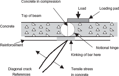
The discussers' question (b) raises a much more complex behaviour of the beam near the edge of the load at the top. At the edge of the loading plate (see Fig. 2 of the original paper and Fig. 11 below), the depth of the concrete up to the main longitudinal top reinforcement is subjected to a high compressive stress. The stress increases as the load is increased and as the beam undergoes further deformation. Simultaneously, the beam tends to separate further along the diagonal crack, as the crack itself tends to extend. The diagonal crack, which is caused by the tensile stress in the concrete and the large compressive stress at the edge of the loading plate, is separated by the top longitudinal reinforcement. It is clear that the top reinforcement acts as a ‘notional hinge’ or a neutral axis position, which is tending to undergo a sharp bending, forming a ‘kink’. It can be argued that, depending on the size and amount of reinforcement, a part of the reinforcement contributes to the compression resistance until crushing happens. This is the force C2 in the original paper. In mode of failure 2, it has been found appropriate to ignore the contribution of the top reinforcement in the value of C2. However, it is important to understand the physical significance of the top reinforcement in bringing about the observed structural behaviour.
The discussers have pointed out that, in the paper, the values of Pst2 and V3 are calculated using two different methods for the two mechanisms. This is indeed confirmed, but with some qualifications. Pst2 and V3 are again forces at the positions where crushing of the concrete occurs at failure. These positions also act as ‘notional hinges’ as discussed earlier. First and foremost it is important to maintain the equilibrium of the blocks under the assumed forces. Then it is important to recognize that in small local areas such as positions 4 in Figs 2 and 4, as discussed before, there is no absolute certainty of how much contribution exactly the reinforcement will make while it acts as a hinge separating the two actions on either side of it in the concrete. It is considered that in the paper the values chosen are realistic. This is also a point, which might require further attention.