

R. Lawther, University of New South Wales and H. R. Ronagh, University of Queensland
This paper derives formulae which eliminate the iterative steps of moment distribution. They are found by performing the iteration symbolically, and summing the consequent geometric progressions.
If the aim is to derive closed-form formulae then the reference to moment distribution in the title gives it a relevance that is not appropriate. A closed-form solution is a solution of the structural model, independent of how it might be analysed. Any analysis performed symbolically must give the same result. A symbolic elimination of the stiffness equations avoids the geometric progressions, and is simpler because of this.
The major drawback of closed-form solutions is that they are specific to the configuration. A structure with two joints and a structure with three joints have quite different formulae (as is clear from the paper, and even here the equations presented are not completely general). Things are getting complicated, and we have not seen any more than three rotational freedoms, let alone a configuration with translational movement.
If the aim is to provide a competitor, it has to compete with moment distribution's major attractions
Physical appeal. The analyst is familiar and comfortable with the parameters of the algorithm. Moment distribution is a stiffness analysis, with displacements as primary results. Internal actions follow from post processing. Moment distribution combines the post processing with the solution, hiding the displacements so only the more familiar moments are dealt with.
Simplicity. Distribute the unbalanced moment at a joint among the connecting members, with carry-over to the other ends of these members. Repeat as necessary.
Universality. This simple algorithm applies to all structures that fit the model. Even in the case of sway structures, which may appear different, the difference is in the details of calculating the fixed-ended moments. The moment distribution is the same.
The proposed method is clearly equal with moment distribution on point (a). How well it competes on point (b) may be arguable. How well it competes on point (c) is not. Hardy Cross used a simple structure with five freedoms in his original paper on moment distribution,1 which set the course of analytical history for several decades. If a parallel paper had appeared simultaneously, with the same structure solved by the proposed method, how different might this history have been? Any contest would be part of a long competition between algorithmic and formulaic solutions. Algorithmic solutions have been winning this battle decisively for quite some time now, and the present paper is unlikely to shift the balance.
The popularity of moment distribution has fallen in proportion to the popularity of digital computers, but its relevance has not. It is an excellent method for solving simple structures, and for finding approximate solutions for more complex ones, which makes it particularly suitable for verifying computer results. In a fair world its popularity would rise with the use of computers, not fall. It deserves continuing exposure, and this is the real contribution of the paper.
T. J. Upstone
The distribution method used by the authors is called ‘The Hardy Cross Moment Distribution Method’, and was first published by Professor Hardy Cross in 1930.1 It is an iterative arithmetic process which has been proved to be extremely useful for the calculation off the end moments in the members of stiff-jointed frames, such as single- or multi-bay portals, multi-bay–multi-storey buildings, and continuous girders. The writer was introduced to the method by Professor J. F. Baker, later Lord Baker, at Bristol University in 1937 and he used it extensively ever since.
The authors have found, remarkably, that the interactive processes can be expressed by finite algebraic functions for the moments in the members of the frames they have considered. Their case studies 2 and 3 are of portal frames which are prevented from sway, due to horizontal loads, or lack of symmetry of members, or vertical loading, by additional member c–e. (Figs 3 and 4). A portal frame is shown in Fig. 1(a), which is free to sway under vertical loading or horizontal loads. The multi-bay, multi-storey building frame shown in Fig. 1(b) is also free to sway. The general Hardy Cross method incorporates the sway effects of such frames by using two operations at each iterative step, which are additional to those of balancing the moments and carrying over the moments, as given in the paper. After the ‘balancing’ and ‘carry-over’ steps in each iteration, the sum of the moments at the top and bottom of all the columns in each storey is calculated. The total sum for each storey should be zero in a ‘free’ frame, if there are no horizontal loads. Where there are horizontal loads the total sum of the column moments should balance out the shear moments created in the columns by the horizontal external loads. If these criteria are not met and there are residual shear moment in the storeys, then an equal sheer moment of opposite sign is added to the sum of the storey column moments. This moment is distributed to the tops and bottoms of the columns using distribution factors for each column. These factors are different from those used to distribute the out-of-balance moments at the joints (see Appendix 1). In the next interative step these sway moments together with the carry-over moments are balanced out at each joint in the usual way. These steps are carried out after each carry-over operation as the iterative process continues until the required degree of accuracy is reached.
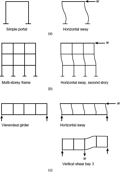
The Hardy Cross method can also be used to calculate the moments in a Vierendeal girder, (Fig. 1(c)). In this case the girder will sway horizontally due to vertical or horizontal loading, but also each panel of the girder can shear vertically. This vertical shear is balanced out panel by panel in a similar way to sway, by distributing cancelling moments to the ends of the chords of the panel.
The operation of the Hardy Cross method is shown with examples in Reference 2.
If the author's algebraic solutions are to be of general use, the additional relative terms to allow for sway and shear must be added to the formulae already given in the paper. The writer believes these terms to allow for sway and shear would render the algebraic functions impracticable for all but continuous beams and frames where sway is structurally prevented, such as in Figs 3 and 4 in the paper.
APPENDIX 1. FACTORS FOR DISTRIBUTION OF OUT-OF-BALANCE MOMENTS
The general expression for the distribution factors is not given in the paper.
The factors for the distribution of unbalanced moments at a frame joint are calculated from the general expression, below, for each member at the joint where I is the moment of inertia and L is the length of the member.
The writer has mentioned further sets of distribution factors for a sway and shear. The factors for the distribution of unbalanced moments in a storey or panel of a frame are calculated from the general expression, below, for each member in a storey or panel.
If the members in a storey or panel are all of the same length then this expression becomes
Author's reply
The authors have not responded to these discussions.
