


6. INTRODUCTION
The authors are to be congratulated for a timely article investigating the effect of cracking on deformation behaviour and crack width development of concrete reinforced with carbon fibre-reinforced polymer (CFRP) bars. Serviceability behaviour is especially important with FRP bars because of their low stiffness as noted in the paper, and tension members are often used to investigate the tensile contribution (tension stiffening effect) of concrete in flexural members such as beams and slabs. The discusser would like to focus on five issues: (a) errata to equations; (b) the effect of bond on tension stiffening; (c) the effect of shrinkage on tension stiffening; (d) the method used by the authors to measure member deformation; and (e) code prediction equations.
Author's reply
The authors are grateful to Professor Bischoff for his interest and his comments. The tension stiffening effect is fundamental for a reliable serviceability analysis of concrete structures and its study imposes accurate and detailed procedures both theoretically and experimentally. Before addressing the other comments raised in the discussion, it is useful to outline the aims of the paper. These are
the evaluation of the tension stiffening contribution in the serviceability analysis of the FRP reinforced concrete elements
the definition of a reliable model of analysis of the serviceability behaviour of FRP reinforced concrete structures that takes into account both the effective behaviour of materials (FRP and concrete) and their interaction.
7. ERRATA TO EQUATIONS
Equations (1), (6) and (8) are not dimensionally correct. Equilibrium connotes a balance of forces and not stresses. Hence, the left-hand side of equations (1) and (6) should have the differential stress dσr multiplied by the area of reinforcement Ar. For equation (8) it is noted that uniform bond stress along a reinforcing bar in a cracked axial member is analogous to a pile with frictional resistance distributed uniformly along its sides. Solution to this problem gives an average strain of
that equals
when using equation (7) with equal μ to the reinforcing ratio Ar/Ac. In other words, the concrete carries an average stress of 0·5fct between cracks, since the concrete stress fc varies linearly from zero at a crack to fct midway between cracks when bond stress is uniform. Assumptions in the model correspond to a stabilised cracked pattern with a maximum spacing of 2lmin, although the average crack spacing typically equals about two-thirds of the maximum value. Behaviour during the crack development stage is also not being modelled. Equation (11) should read
where the reinforcing ratio μ is based on an effective tensile area of concrete with a width up to 2·5c surrounding the bar. The bond coefficient k1equals 0·8 for deformed steel bars, while k2 is a strain gradient coefficient equal to 1·0 for axial tension and does not depend on the load duration. Ghali and Favre12 provide an excellent summary of serviceability requirements specified in the Eurocode EC2. Could the authors also explain the difference between the terms diameter and effective diameter given in Table 1?
Author's reply
Equations (1), (6), (8) and (11) were reported incorrectly in the text, however numerical results were obtained considering the correct relationships, reported in the following
The k2 coefficient depends on strain distribution; as correctly reported in the discussion.
The term ‘diameter’ in Table 1 refers to the outer diameter values of tubes used for casting cylindrical specimens, while the effective diameter is that of cylindrical concrete specimens. The former was reported in the text because it was used to identify the tested specimens (T40…T80).
8. EFFECT OF BOND ON TENSION STIFFENING
Tension stiffening is dependent on having some bond between the reinforcing bar and concrete, but is not necessarily affected by changes in bond strength when using different types of reinforcement. For the authors' model (Th2) based on uniform bond stress, a bar with half the bond strength (0·5τad) will have twice the crack spacing and larger crack widths will develop because of this. The maximum concrete stress between cracks, on the other hand, remains equal to fct because the bar now has twice the distance available to transfer bond forces back into the concrete. The tension stiffening effect characterised by the average stress in the concrete then remains constant at 0·5fct (refer to section 7). Hence, changes in bond affect the crack spacing and associated crack widths but not tension stiffening in this case (unless bond deteriorates once cracking has stabilised). Note that the concrete strength midway between cracks should typically be less than fct when cracking has stabilised (see development of the authors' model Th1).
Author's reply
The model Th2 is founded on the assumption of perfect bond between the FRP reinforcement and the concrete. This model, however, is not perfectly correct to analyse the tension stiffening of FRP reinforced-concrete element because of the presence of slips at the interface FRP to concrete. A correct model has to takes into account the bond–slip law at the interface FRP-to-concrete (model Th1 in the text). In this case the concrete strength midway between cracks depends on the bond–slip law that is different from each type of used FRP reinforcement.
9. SHRINKAGE INFLUENCE
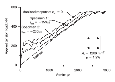
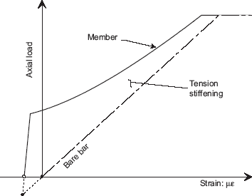
Shrinkage has a significant influence on the measured tensile response as shown in Fig. 17 for steel reinforced axial members cast from the same concrete batch and identical except for curing conditions.13 The specimen with more shrinkage (εsh) shows an apparent reduction in tension stiffening and lower cracking load. This occurs because shrinkage of concrete causes initial shortening in a tension member before any axial load is applied, leading to an offset between the bare bar response and measured member response (Fig. 18). Since tension stiffening is measured by comparing the difference between these two responses, failure to account for a shift in the bare bar response will give an incorrect measurement of the tensile contribution of concrete. This is particularly important when test results are used to validate and/or calibrate theoretical models such as those proposed by the authors. Test specimens with the reinforcement unbonded can be used to validate the shift in bare bar response.13 The reduction in apparent tension stiffening increases with reinforcing ratio as well when shrinkage is neglected as in Fig. 17,13 and this will skew the authors' test results since the reinforcing ratio of their specimens varies with changes in the concrete cover. Could the authors provide curing details of their specimens?
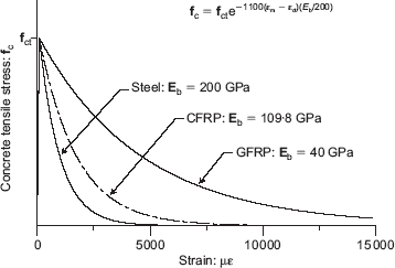
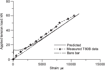
Axial tension tests carried out by the discusser for steel and glass FRP (GFRP) reinforced concrete have shown that tension stiffening is independent of the reinforcing ratio when shrinkage is included in analysis of the member response.14,15 This work has led to a generalised material property that represents the average tensile response of cracked concrete fc relative to the initial cracking strength fct. Fig. 19 compares the material response of steel and GFRP reinforced concrete with the material response expected for CFRP reinforced concrete. The predicted response of member T80 is then plotted using the proposed constitutive relationship for CFRP and compared with the authors' measured values in Fig. 20. Differences between measured and expected behaviour lead to questions about how member deformation was measured.
Author's reply
All specimens were cured at the same conditions, namely room temperature (T = 20–22°C) for at least 28 days. Results presented in the paper do not take into account the influence of shrinkage on tension stiffening effect. The topic is of relevant importance, as discussed in the note. It was not, however, addressed at this stage of research, nor was the possible influence of long-term phenomena. On the basis of interesting results obtained by the discusser, the progress of the presented work could aim to consider the influence of shrinkage on the tension stiffening effect. In addition, as already mentioned, it is also suggested that the influence of other phenomena are also taken into account.
10. MEMBER DEFORMATION MEASUREMENT
Member deformation of the uncracked response is obviously not being measured with the test set-up used by the authors. At first glance it appears that shrinkage caused the specimens to crack before testing16 but reinforcing ratios are probably not high enough for this to happen.13 Specimen elongation was determined from an LVDT measurement of the moving cross-head (Δcross-head) and another LVDT that measured movement at the outer edge of one end of the specimen (Δend). Given that equal lengths of bare bar are exposed at both ends of the specimen and assuming no slip occurs in the grips, member deformation could have been approximated with ΔL = 2Δend − Δcross-head. Accuracy of this approximation depends also on the specimen end remaining planar. Could the authors please give details on exactly how ΔL was calculated?
The authors observed that tension stiffening increased with axial force, which is contrary to what is expected (see Fig. 19), suggesting that the assumed bare bar stiffness may be too low. It is, however, more likely that measurement of deformation was affected by eccentricities and the position of the LVDT on the end face of the specimen. Eccentric loading is unavoidable once the member cracks, making it important to measure deformation on both sides of the specimen so that an averaged response can be determined. This uncertainty in deformation measurement of the authors' specimens makes it difficult to draw definite conclusions. A more orthodox method of measuring specimen deformation would have been to attach two diagonally opposite LVDTs to brackets firmly clamped onto the specimen at each end.
Author's reply
Given that the bottom grip of the testing machine is fixed, ΔL was evaluated by the recorded displacement of the LVDT used to measure the elongation of the specimens (section 2·2), mentioned in the note as Δend. From the measured value (Δend) the deformation of the bare bar at the bottom of the specimens was detracted. The second LVDT was used to check the bare bar elongation (ΔL(bare bar) = Δend − Δcross-head).
11. CODE APPROXIMATION
Accuracy of the ACI Code approach given by equation (18) with α = 1, depends solely on the ratio of uncracked to cracked area Ag/Acr.15 This equation does not work well when Ag/Acr exceeds a value of approximately 4, giving a response that is much too stiff—as observed by the authors. Specimen T80 has a reinforcing ratio μ close to 1% giving Ag/Acr ≈ 25, which is much greater than the limiting value of 4, while specimen T50 has a greater reinforcing ratio of μ = 3·4% (based on effective diameter), which gives a lower ratio of Ag/Acr ≈ 9 resulting in better fit with the test data. The EC2 Code approach also overestimates tension stiffening at lower reinforcing ratios13 but not to the same extent as the ACI equation.15 This is in agreement with the authors' test data. It is noted also that the calibration coefficient α used in equation (18) effectively reduces the ratio Ag/Acr to achieve a better fit with the test data. Using a value of α = 0·162 proposed by the authors for CFRP reduces Ag/Acr from 25 to about 4 for specimen T80. Engel et al.17 proposed a similar value of α for CFRP beams.

