
1. VIRTUAL LIBRARY
The ICE Virtual Library now contains every paper published in the ICE Proceedings from 1836 to the present time. This represents an enormous repository of information of use in many ways to us all. Not the least is the historical interest and the opportunity to see how changes in working practises and attitudes to design and maintenance have changed.
These records have I know been used frequently by engineers researching particular topics and also on several occasions when structures have come to need repair, extension or replacement. Often the ICE Proceedings papers are the only extant records of some. Having the information on-line is a major step forward in accessing this mine of information easily and quickly.
As an example of what is available and one I think is also of topical interest I have selected a paper from 1952, just over 50 years ago, on railway maintenance and on the next 3 pages are some extracts from it.
I am considering selecting other papers from the past from time to time, if you would find this of interest let me know.
Information on accessing the Virtual Library can be obtained from the ICE website at www.iceknowledge.com
2. AWARDS
Papers published in Transport each year are eligible for awards from the Institution of Civil Engineers. Papers in any of the ICE journals can be nominated for several awards, the Telford Medal, the George Stephenson Medal and the Baker Medal. In addition each journal has awards dedicated to their specific subject area.
The following papers from the 2002 volume of Transport have received awards.
| Howard Medal | Northern Line tunnel reconstruction at Old Street, Nicholas Burgess, Jon Fagents and John Paterson; Transport, 153, No. 1, 1–11 |
| Rees Jeffries Award | Research and development in discrete element paving systems, Professor J. Knapton and I. D. Cook, Transport, 153, No. 1, 13–23 |
| Webb Prize (1) | Channel tunnel rail link—high speed, low impact, minimum cost, Ted Allett, Richard Greer and Chris Manning, Transport, 153, No. 2, 71–78 |
| Webb Prize (2) | Evaluating safety performance of road projects, Hoong-Chor Chin and Emily Tan, Transport, 153, No. 3, 191–196 |
3. PAPERS FOR THE JOURNAL
Papers for the journal come from several sources. Panel members suggest potential authors for subjects likely to be of interest, some come from seminars and conferences and some are directly offered by authors for consideration. Future issues will be covering Transport Planning, and Railways and Airports.
We are always prepared to consider direct offers of papers and if you feel your subject within the broad field of transport is underrepresented then the panel would welcome suggestions and, even better, papers.
“Some Major Problems in Railway Civil Engineering Maintenance”
SYNOPSIS
One of the most important functions of railway civil engineering is the efficient maintenance of the permanent way and structures. There are, however, numerous problems, many of which disappear as a result of good organization, but many technical difficulties are present which vary to some extent in nearly every case.
The Author draws attention to the fact that as a result of loads gradually increasing on railways, and many structures nearing the end of their useful life, many maintenance problems are having to be solved. Examples of these are given concerning permanent way, earthworks, bridges, tunnels, major roofs, etc., and solutions which have been adopted are described.
The greatest problem of all is the carrying out of these works with the minimum interference to the traffic, and this is probably the most important factor involved in deciding on the action to be taken.
Introduction
Civil engineering maintenance does not sound a very interesting subject to those who have no experience of it, especially to students finishing their course of theoretical training. The fact is, however, that the circumstances in which the work has to be carried out and the limited time which is usually available for doing it bring a great deal of interest to the problems; furthermore, the engineer responsible for maintenance has to make decisions based on a combination of theoretical training, practical experience, and common sense.
This is probably more so in railway work than in other branches of civil engineering because interference with the smooth running of traffic must be as small as possible, but at the same time the weights and speeds of trains necessitate careful consideration being given to the strength of work which is put in. Because of vibrations set up by traffic special care has to be taken in designing temporary works, such as timbering of excavations.
In most cases trains cannot be diverted and, whenever possible, work must be carried out without stopping them except possibly for a few hours in the middle of the night. The imposition of temporary speed restrictions can be allowed to a certain extent. Mechanical plant can be used only when there is no possibility of fouling passing traffic, or when precautions can be taken to ensure that it is clear before traffic approaches.
As a result of these difficulties, the cost of repairs is bound to be high and maintenance considerations become important factors in the design of new works. To the uninitiated, railway works often appear to be heavier than necessary, but in the long run this is more economical. Retaining walls supporting embankments carrying fast-moving traffic must be sufficiently strong to be able to withstand a high degree of compaction behind them, combined with vibrations in the material they are supporting. Buildings must be sound and robust so that they do not suffer from the shaking effects of passing trains. The steelwork of station roofs, sheds, and bridges over the line is exposed to the corrosive action of sulphur in engine smoke, and it is worth while allowing a little for this in the design, especially in thinner sections.
Maintenance problems are of infinite variation and it is impossible in this Paper to deal with more than a few of them. The Author therefore gives details of works on the Southern Region of British Railways with which he is familiar, but which are no doubt similar to those encountered elsewhere, with the object of bringing out the main principles involved.
They are considered under the following general headings:—
Permanent way.
Formation and foundations.
Slips.
Scour.
Tunnels.
Bridges and roofs.
Permanent Way
The problem of track maintenance is basically one of organization.
The maintenance of good line and level is the direct responsibility of the Length Ganger, who receives close supervision from his Permanent Way Inspector. These men are essentially practical and no amount of theory can replace the experience they gain over a period of many years. Nowadays, however, every endeavour is made to give them some theoretical knowledge by persuading them to attend special evening classes, and there is no doubt that as a result they take greater interest in their work and therefore produce better results, but the fact cannot be overlooked that some of the best gangers are the older ones who have been brought up on the track since they first started work.
Technical supervision must be given by the District Engineer and his assistants. In the Author's opinion, by far the best way of doing this is for the District Engineer regularly to walk all the routes under his control, accompanied by the particular Inspector concerned. He is then able to see for himself that the standard he desires is being maintained, or where this is not so, he can take the necessary steps to ensure that an improvement is effected. Contact between the engineer and his men is invaluable, and many of the gang's difficulties—which would not otherwise be known—can be solved by discussion on the site. Inspection by trolley or by special coach cannot take the place of these walks, but certainly give a useful additional means of keeping in touch with conditions of way and works over a longer length of line in a shorter time.
The annual marking of lengths, now standard on British Railways, is a valuable additional means of helping the District Engineer to know the condition of the track for which he is responsible.
The theoretical aspect of track work deals more with junctions and connexions than plain line, but practical experience is essential in order to produce a lay-out which can be put in position in the time available and to give as few maintenance difficulties as possible afterwards.
Electrification and the increasing weight of modern traffic give a tremendous pounding to point-and-crossing work so that at very busy junctions too high a proportion of the gang's time is spent in keeping the various bolts and fastenings tight. At the same time the crossings themselves wear down quickly and, until a few years ago, replacements had to be put in frequently when traffic could be stopped for a time.
More recently, this latter trouble has been met by making good the wear with metal deposited on the worn surface by either the electric arc or oxy-acetylene welding process. Both the above types of trouble, however, are greatly reduced by making those parts of the junction where the greatest impact is experienced in cast high-manganese-steel material. As can be seen in Figs 1 (facing p. 120), much fewer parts are required in the make-up of such crossings, and the gangers work of keeping the bolts tight is consequently reduced considerably; but in addition the better wearing qualities reduce the work involved in making up the worn surfaces by welding and the replacement of crossings when worn out.
A complete lay-out of this type was installed in 1944 at Borough Market Junction where traffic from Cannon Street and Charing Cross Stations converge. The original material is still in use, but previously crossings had to be changed or pulled back every few months, and much of the ganger's time was spent daily in tightening up the fastenings. Creep has been eliminated.
Other similar schemes were put in at Lewisham Junction in 1950 and Metropolitan Junction in 1951 and have given excellent results.
These lay-outs are, however, very expensive and can be justified only in places carrying very frequent and heavy traffic.
On British Railways, about 2,000 miles of track are renewed each year. Because of the shortage of labour which has been experienced since the war, methods have had to be adopted for doing much of this important work by machine, and a large mileage is now carried out by the pre-assembly method, using either cranes or track re-laying units. The latter are particularly useful in tunnels and were described by the Author in a previous Paper.1
To meet modern conditions, a great advance has been made in the use of various types of portable mechanical plant, but this is too wide a subject to be included in this Paper.
Viaducts
Generally, brick or stone viaducts and arches have given little trouble on railways except in colliery areas, where subsidences present a very difficult problem. Many viaducts built in the earliest days of railways are now carrying heavy modern traffic without trouble, but some have shown signs of over-stressing. In many cases the cause has been found to be due to bad construction, not design.
The original viaduct of the London-to-Greenwich railway, built in 1835, is satisfactorily carrying the Southern Region electric and steam traffic out of London Bridge Station, and no difficulties are experienced, but one of the several widenings built many years later has shown signs of failure. Upon investigation it was found that although the surface brickwork of the piers was sound, the interior was loose and hardly any mortar had been used. Repairs were carried out by erecting heavy timber centering under the arches either side of a pier, which was then rebuilt in 10-foot lengths. This had to be done to a whole series of piers, and took several years to complete.
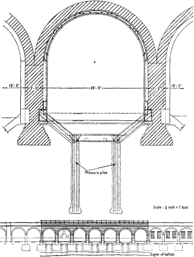
In another case nearby, a slight sinkage in a short length of a long viaduct gave the maintenance staff a considerable amount of concern because the foundations were obviously sinking slightly, and it was feared that the same trouble might spread to a greater length of the structure. Investigation showed that the ground consisted of 5 to 8 feet of loam, on about 4 feet of good ballast overlying 40 to 50 feet of fine sand. It was not known whether the viaduct was on piles, which in any case might have deteriorated, or if there had been local relaxing of the sub-strata, since the general level of groundwater was known to have fallen gradually over a period of years. After further investigation it was considered that the subsidence was brought about by the large weight of metal and other commodities stored under one of the arches by a tenant. The weight was estimated at about 400 tons, part of which was on the footings of the piers. The compression of the ground on which the viaduct and the stored load rested showed up in the elevation of the structure.
The scheme for relieving the foundations is shown in Figs 11. It was successfully completed without the imposition of a speed restriction on traffic over the viaduct.
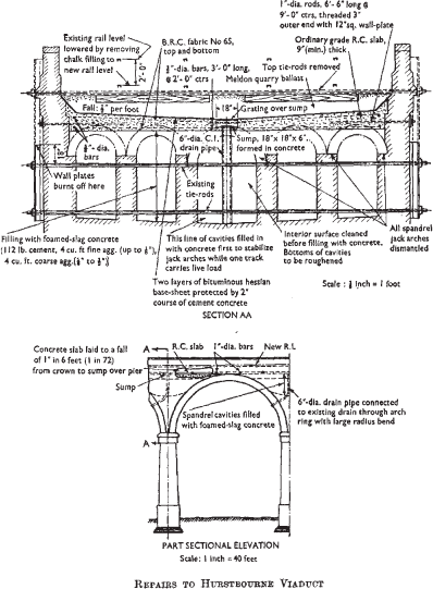
Another interesting problem was encountered at Hurstbourne, between Basingstoke and Andover. The Bourne valley is crossed by a viaduct with a maximum height of 65 feet, consisting of nine semi-circular brick arches each of 46 feet span, carrying two tracks. The permanent way was originally supported on these by five longitudinal jack arches springing from walls built up from the arch rings and piers. These were of relatively light construction and had gradually deteriorated since they were constructed in 1854. Extensive repairs therefore became necessary.
The simplest solution would have been to replace the walls and jack arches by concrete, but tests indicated that this increase in weight at the high level would have been undesirable, and would probably have caused the viaduct to sway under fast-moving heavy trains, foundation trouble might also have resulted.
The scheme adopted therefore consisted of:—
Replacing the jack arches by lightweight mass concrete.
Laying a continuous waterproofed 9-inch-thick concrete slab throughout the length of the viaduct, laid to falls for drainage purposes.
Lowering the track by 2 feet to prevent any increase in the final dead load.
The mass concrete was of particular interest. Its aggregate was of fine and coarse foamed slag, and when it had set, its weight was only 60 per cent of that of normal concrete.
It was fortunate that the track could be lowered 2 feet, since this enabled more than 1,000 tons of ballast to be removed and so to a large extent the extra weight involved in the repairs was balanced.
Single-line working at a speed of 15 miles per hour was arranged, first on one road and then on the other, so that half the width of the viaduct could be dealt with at one time.
In order that the stability of the structure could be assured while only half the width of the viaduct was subject to live load, it was necessary to fill the spandral cavities before any appreciable amount of ballast was removed. Timbered excavations were therefore sunk over each pier for the half width of viaduct of which possession had been obtained, and the jack arches broken through. Concrete was then packed in so that for the whole length of the viaduct for the half-width being treated the space between the ballast and the rings of the main arches was more or less solid.
In order to support the track which was open to traffic while the ballast of the other road was removed, a wall consisting of bags filled with sand and cement was built in a trench alongside the sleeper ends. When the brick deck over the spandrel arches was exposed, it was found that the mortar had perished, and there was no difficulty in removing it. The placing of concrete then continued and was followed by the reinforced-concrete slab, waterproofing, and track ballast. When the permanent way was completed, the line was opened to traffic and the other road treated in the same way.
Some details of the scheme are shown in Figs 12 (p. 126).
The intermediate piers of Charing Cross Bridge consist of a series of cylinders, about 7 feet in diameter. They are made up of hollow iron sections, filled with what is suspected to be loose rubble. Some of the sections have cracked from top to bottom.
To prevent conditions getting worse, steel straps were placed round the faulty cylinders, as shown in Figs 13 and 14 (facing p. 121).
The Port of London Authority, however, required that projections from the original work should be as small as possible, in order that river craft, both small and large, could pass without danger of damage. The straps were therefore joined by welding and the method adopted is as shown in Fig. 14. The lower part shows a strap tightened up and held in position ready for welding. The upper part shows the finished joint, with the outstanding legs of the temporary angles burnt off.
Owing to the increase in weight which has to be carried by viaducts and arches, there are many cases in which the spandrel walls have started to give, often tending to slide along the top of the arch. In many instances the movement has been stopped by putting steel ties between the opposite walls. It is, however, essential to cover their whole length with some compound to prevent corrosion, because they are not easily inspected and failure could occur with little warning.
Where the spandrel wall tends to tip outwards this same method can be used, or alternatively the walls can be thickened. The latter method was used at Oxted Viaduct, where it was also desired to rebuild the parapet walls in order to give greater clearance from traffic.
On this same viaduct, other trouble was being experienced. In two arches, the lower two rings of the four rings of brickwork had fallen away slightly from the others, the cause of which was not ascertained with any certainty. The two rings were therefore taken out and rebuilt. This latter type of work is one which is not unusual in arch maintenance. Drummy brickwork is often a sign, of coming trouble, and if reasonably early action is not taken, more extensive faults will develop. Cases have been known of part of an arch ring falling out.
A big problem is presented by some of the larger station roofs. That at New Street, Birmingham, has been taken down; that at Cannon Street will probably be taken down in a few years’ time, and schemes are on foot for similar action at other stations. The modern tendency is to build lower roofs of the umbrella type over the platforms, or canopies projecting from the station buildings, except over terminal concourses.
Some of the bigger roofs must, however, be maintained for many more years. One such is over the so-called “Central Section” or the former London, Brighton and South Coast side of London Bridge Station. The greater part of the roof is in very good condition, but some of the arch spans at the ramp end of the platforms have corroded to such an extent that it was considered unsafe to replace the glazing after the war. They are therefore being reconstructed.
In this case, in order not to detract from the general appearance of the roof, it is necessary to adopt a design similar to that which is to be replaced. The part of the station it covers cannot be closed, for traffic reasons, and suitable gantries or staging for assembling or erecting a steel roof are not practicable. The present arches are not sufficiently strong to haul up heavy material and therefore it has been decided to reconstruct part of the roof in aluminium, which can be done from a relatively light gantry, constructed so as not to interfere with traffic. This is the biggest work in aluminium so far authorized on British Railways, and should prove of great interest.
Conclusion
The Author has endeavoured to show the great variation of tasks which have to be undertaken by those responsible for the maintenance of a railway. He is aware, however, that there are many others which are of interest, but space is not sufficient for them to be included.
His intention has been to give main details of some works in which special features were involved, hoping that in the discussion members will be able to give examples which have been treated in a different way.
Acknowledgements
The Author wishes to record his thanks to Mr F. E. Campion, M.I.C.E., Civil Engineer of the Southern Region of British Railways, for permission to refer to the various works mentioned in the Paper, and to various members of his staff for help in checking information given.
The Paper is accompanied by nine photographs and six sheets of drawings, from which the half-tone page plates, the folding Plate, and the Figures in the text have been prepared.
