


Current night trains pose a challenge to economic efficiency due to ageing vehicles, limited space and high operating costs, among other things. The AliSa project is rethinking European night trains by developing a modular and lightweight sleeping car concept. A coach concept is being developed that addresses these challenges through the use of advanced lightweight construction methods and sustainable materials to improve both comfort and cost-effectiveness. One of the most important innovations is a modular coach concept with a modular interior that allows flexible use in both day and night operation. The coach concept is divided into three separate but permanently coupled coaches, which can be easily coupled with other groups of three depending on daily requirements. Each coach has modular compartments that maximise privacy and optimise space utilisation. This improves overall capacity utilisation and reduces operating costs. Structural optimisations are being made to the car bodies to reduce weight and increase cost-effectiveness. The AliSa project shows that, despite increased passenger comfort, the adapted and holistic modular design leads to a lower environmental impact and improved cost-effectiveness. In this way, the passenger density in night-time operation can be increased by up to 39.4% compared to the state of the art.
1. Introduction
Night trains in Europe face major economic challenges due to outdated rolling stock, limited space and high operating costs (Heufke Kantelaar et al., 2022). Compared to other forms of mass transport such as long-haul flights or high-speed trains, the demands placed on night trains are particularly high. Studies show that 50% of passengers expect guaranteed privacy and 80% want to be able to lie down (Bauer and Bellmann, 2019). The demand for a high level of comfort, which is closely related to privacy and the number of people in the compartment, is also one of the main reasons for choosing this mode of transport (Heufke Kantelaar et al., 2022). Beside this higher comfort, night trains offer another decisive advantage over aeroplanes: significantly lower carbon dioxide emissions. Electrified trains are locally emission-free during operation, and the carbon dioxide equivalents of long-distance rail transport are 76.5% lower than those of international flights (Allekotte et al., 2021; Bothe, 2024). For distances between 1200 km and 1800 km (up to 2400 km in a high-speed variant), night train travel is economically beneficial. Outside this range, night trains are not competitive and unprofitable in the short to medium term (Bellmann and Schönberger, 2016). If intra-European short-haul flights up to a distance of 1500 km were to be banned, this would require night trains to be consistently geared towards users. A ban has already been considered in Germany and implemented in France for destinations that are less than 2.5 h (approx. 500 km) away by rail, initially for a period of 3 years (ZEV, 2023).
To make night train travel attractive, it is important to offer a high level of comfort as well as cost- and time-efficiency (Rüger and Mailer, 2020). To meet these requirements, extensive technical systems (air conditioning, infotainment, wet rooms, etc.) and a comfortable interior design are necessary. These are two factors that increase the mass of the vehicle and thus reduce the payload fraction, which in turn leads to a reduction in energy- and cost-efficiency of the overall system. In addition, an interior design with a high passenger density is required (Schlaak and Nagl, 2008). Increasing capacity has the greatest impact on reducing the cost per seat without compromising on quality (Bode et al., 2025). This must be balanced with a high degree of privacy and a quick and easy transition between daytime and night-time operation. Night trains can only be operated profitably if they can be integrated into daytime traffic, thereby reducing downtime (Schlaak and Nagl, 2008). This is an inherent disadvantage of the current night train service. Sleeper cars and couchette cars, which are often outdated, are only suitable for night-time transport and cannot be used during the day. However, using the vehicles in daytime transport can increase productivity and thus double the economic efficiency of the vehicles (Gerfried et al., 2007). As yet, no vehicle that can be used entirely for night-time and daytime transport has been developed. To exploit this potential, the vehicles must offer both the necessary comfort for night-time transport and a high passenger density for daytime transport. Previous studies and start-ups have mainly focused on retrofitting existing passenger coaches (Lebedew and Ksienrzyk, 2025; Rüger et al., 2024). However, they only consider partial aspects such as maximising comfort or easily switching from day to night configuration. They do not take into account the overall system and the associated restrictions due to equipment, compartments for passengers with reduced mobility (PRM) or technical areas, and the required high passenger density (Rüger et al., 2024).
The ‘AliSa’ project (‘Differentiated, lightweight and innovative sleeping car concept’, funding number: 19|23011), funded by Germany’s Federal Ministry for Economic Affairs and Energy, is developing a new modular and lightweight sleeping car concept that takes all these restrictions into account. Thanks to a holistic approach, the concept offers more space and thus greater comfort. The lightweight construction concept developed enables compliance with the original axle loads. The following section discusses the methodology, the factors for economical operation, the overall concept, the interior concept and the car body development. The results and findings are then discussed and summarised.
2. Methodology
Initial economic analyses of the profitability of night trains were carried out and the most important influencing factors were identified. Subsequently, the soft requirements and needs were compiled in co-operation with the various interest groups (user groups, politicians and non-governmental organisations such as the Federal Association for the Self-Help of Physically Disabled People). This resulted in various use cases and interfaces for the new night train concept that needed to be taken into account. At the same time, the requirements from (inter)national approval standards were coordinated and the resulting dimensions of a sleeping car were compiled. In parallel, a mass balance of the concept and all relevant equipment units was created. This requirements analysis showed that the concept to be developed must be modular both within a car body and in a train set. From this, a shell and a modular overall concept were derived. The interior concept was then created in a second step. For this purpose, a basic layout was created, and the partition walls and interior components were designed in accordance with the previously defined requirements. In parallel and in coordination with this, the load-bearing structure of the shell was created. The modularity and approvability of the concepts were considered as central requirements from the outset and were constantly reviewed.
3. Factors for economical operation
As explained by Schlaak and Nagl (2008), a double-decker concept offers lower costs per usable space. This fact makes the double-decker concept a promising approach to reconciling two competing requirements: high seating capacity during daytime operation and sufficient space for sleeping accommodation at night. Double-decker sleeping car concepts from 2008 met with only limited acceptance, mainly due to the cramped conditions on the upper deck. In addition, these concepts were not designed for daytime traffic, which is why they had long downtimes. These early coaches were designed with the G1 clearance gauge (4.31 m). However, the larger GC (4.7 m) clearance gauge allows for more generous interior dimensions. A study by Ramboll Deutschland GmbH (2024) also recommends double-decker coaches with a GC gauge, based on the Scandinavian model. For these reasons, the ‘AliSa’ concept is designed as a double-decker carriage for the GC clearance gauge.
The findings of the evaluation carried out at the start of the project have been used to derive objectives, which are described by Paz Martinez et al. (2025) and can be summarised as follows.
Cross-border interoperability on economically long routes.
Double-decker layouts and, where appropriate, partial seat changes increase passenger density without compromising comfort.
Lighter construction and efficient use of space enable additional comfort features despite higher passenger density.
Wide variety of night train concepts in Europe and worldwide: a modular layout should be sought to enable a differentiated offer for the various potential travellers.
Affordable fares should be achieved through operational efficiency, not through compromising on service – fares are a decisive factor for almost all user groups (Bauer and Bellmann, 2019; Heufke Kantelaar et al., 2022).
PRM cabin with its own toilet on the lower deck and priority seats nearby ensure a user-friendly service for people with reduced mobility.
4. Overall concept
To enable flexible train formation, the AliSa project involves connecting three double-deck coaches to form a fixed unit (see Figure 1), which can be coupled with other units. As specified, these have a carriage body structure within the GC clearance gauge with a total height of 4.65 m. To maximise width and increase comfort, short car bodies are used (the axle distance is 12.4 m). This enables a width of 2.96 m. This corresponds to an increase of 5% compared to the Nightjet (Paz Martinez et al., 2025; Siemens AG, 2012). Thanks to the single-wheel bogie (Krüger et al., 2021; Malzacher et al., 2017a, 2017b) and the selected clearance profile, both levels within a unit are fully accessible. This maximises the space available to passengers and allows for an even passenger density. The transition to another triple unit is ensured by way of the upper level, with a digital automatic coupling provided. The passenger entrances are only located in the end coaches of the triple unit.
 The diagram in panel a compares a clearance gauge, G C, with a restriction curve and an envelope curve around the vehicle profile. The diagram in panel b presents a three-car railway vehicle with an overall length of approximately 46.3 metres. Individual car lengths measure 14.9 metres and 14.5 metres. X, y, and z reference axes indicate orientation. Plan and interior layout views identify seating areas, sleeping compartments, service spaces, toilets, circulation areas, and equipment distributed throughout the three connected cars.
(a) Cross-section of the ‘AliSa’ car body; (b) train formation (top) and interior layout for the upper and lower levels (bottom)
The diagram in panel a compares a clearance gauge, G C, with a restriction curve and an envelope curve around the vehicle profile. The diagram in panel b presents a three-car railway vehicle with an overall length of approximately 46.3 metres. Individual car lengths measure 14.9 metres and 14.5 metres. X, y, and z reference axes indicate orientation. Plan and interior layout views identify seating areas, sleeping compartments, service spaces, toilets, circulation areas, and equipment distributed throughout the three connected cars.(a) Cross-section of the ‘AliSa’ car body; (b) train formation (top) and interior layout for the upper and lower levels (bottom)
The individual car body has a standardised compartment size grid of 2.55 m in the x-direction. The concept provides for different categories of compartments, which are divided into five groups
sleeping car compartment: double and single cabins – fully equipped, lockable compartments with seating and sleeping facilities
couchette compartment: sleeper chair and business sleeper – highly comfortable seats with sleeping facilities
seating compartment: seating area
special compartments: cabin for PRM, cabin for families, high-comfort apartment – private compartments tailored to specific needs
other compartments: cabin for staff, WC.
These individual categories are compatible with the standardised compartment size grid. This means that they can be arranged as required. The special compartments are equipped with toilets, making them independent of the other compartments. Shared toilets are available for other passengers. Additional components are required for a fully equipped carriage. The most important components for operation are: HVAC (heating, ventilation and air conditioning), fire extinguishers, switch cabinet, battery, electrical supply units, compressed air tank, compressed air system, circuit breaker box, waste water tank, fresh water tank and luggage storage. The standardised compartment size grid and the flexible and rapid coupling of various triple units enable the different requirements of users, routes and operators to be met both during the day and at night. At the same time, the ability to quickly couple and uncouple two units allows the integration of train coaches with different starting and ending points, but sometimes the same routes.
A basic configuration of the coach (see Figure 1(b)), which is adapted to the user and operator requirements evaluated in this project, achieves a passenger density of 1.77 passengers per metre of train length. The latest night train, the ÖBB Nightjet, has a 30% lower passenger density of only 1.27 passengers per metre of train length (Neumann and Maier, 2023). The ICE 3neo, a comparable train in daytime operation, offers space for 2.19 passengers per metre of train length (Deutsche Bahn AG, 2023). Due to the high passenger density, its use in daytime traffic is economically viable if the pricing is adjusted to the higher level of comfort and, for example, an additional class or business class is introduced.
5. User-oriented interior design
The interior design focuses on a flexible, user-oriented layout of the available space. By analysing potential users, different travel needs were identified. For example, intelligent folding bed mechanisms create seating areas (face-to-face) during the day, while at night the cabins can be converted into double-decker sleeping areas (similar to an Amtrak Roomette (AMTRAK Vacations, 2025), Figures 2(a) and 2(b)). In this way, different usage profiles can be accommodated within a standardised concept. For people with reduced mobility, a separate compartment for up to four people with its own sanitary facilities is provided. This reduces barriers and stressful situations. The two-senses principle is also taken into account. This is intended to enable people with sensory impairments to move around safely by addressing two of the three senses of sight, hearing and touch (DIN, 2014). In this case, announcements are not only made acoustically but also displayed visually on larger displays.
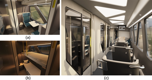
Design concept: (a) compartment during the day and (b) at night; (c) business reclining chair opposite the sleeping cabins
Design concept: (a) compartment during the day and (b) at night; (c) business reclining chair opposite the sleeping cabins
Another focus is on the design of the sense of space. In the single and double cabins, large glazing adapted to the structural optimisation creates a bright and open atmosphere. At the same time, the transparency can be individually controlled: from clear to frosty. This allows for rooms with a high degree of flexibility for the different requirements of user groups and usage scenarios. The choice of colours and materials is based on restrained, natural tones. The side walls are deliberately kept darker to draw the eye to the outside rather than the wall. The design language remains functional and unobtrusive. Straight lines, larger radii and individual 45° angles – inspired by structural elements of the car body – give the interior a clear and uniform design.
6. Car body development
6.1 Weight drivers
In order to operate a night train efficiently, it is necessary that, despite the larger clearance profile and the required more comfortable compartments for passengers, the maximum permissible axle load of 16 tonnes is not exceeded. In order to ensure the axle load for the selected concept with two single-wheel bogies, with the required comfort and number of seats, optimisation of the mass is essential.
During the concept phase, the masses of the individual components were estimated and compiled on the basis of empirical values. From these, the ten largest weight drivers for the end car and middle car were identified. The weight drivers can be found in Figure 3. The ten largest weight drivers account for 72% and 75% of the total mass of the end and middle coaches, respectively. The remaining 25% and 28% of the total mass are distributed across the remaining components, each of which accounts for less than 2% of the total mass. These include, for example, paintwork and cables. Due to their small proportion of the total mass and low mass, these offer relatively little potential for weight optimisation. The components with the largest share of the total mass, 19% and 18%, are the running gear and the car body, respectively. From the outset, the Alisa concept has envisaged the use of a lightweight running gear. This is to be based on the ‘Next Generation Train’ (NGT) Forschungsinfrastruktur NGT-Fahrwerk (FUN) running gear (Krüger et al., 2017, 2021). Due to the high degree of lightweight construction in this running gear, it will not be further optimised in the project. In addition to the running gear, the biggest weight drivers are the car body shell (18%) and the cladding (6%). The third largest share of the mass is accounted for by passengers, at 7% and 9% for the end coach and middle coach, respectively. However, reducing passenger numbers contradicts the aim of increasing the number of passengers per usable area and is therefore not being considered. The remaining seven weight drivers relate to necessary components that can only be optimised to a limited extent, such as air-conditioning systems, sanitary facilities and windows. These each account for only 2–6% of the total mass. Nevertheless, the other weight drivers should also be taken into account in further optimisations of the car body structure. It is clear that the increased vehicle mass due to the complex requirements of the overall system must be compensated for by lightweight construction methods such as lightweight design, lightweight concept, lightweight materials, lightweight forming and functional integration (König et al., 2014). This can be achieved, for example, by integrating the cladding into the load-bearing structure.
 The charts comprise panel a and panel b. Panel a allocates 72 per cent to the 10 largest weight drivers and 28 per cent to others. The expanded breakdown gives Single-axle bogie 19 per cent, Body shell 18 per cent, Passengers 7 per cent, Panelling total 6 per cent, Air conditioning 5 per cent, Toilet 4 per cent, Windows 4 per cent, Insulation 3 per cent, Electrical supply units 3 per cent, and Door interior 3 per cent. Panel b allocates 75 per cent to the 10 largest weight drivers and 25 per cent to others. The expanded breakdown gives Single-axle bogie 19 per cent, Body shell 18 per cent, Passengers 9 per cent, Panelling total 6 per cent, Business seats plus reclining function 6 per cent, Air conditioning 5 per cent, Windows 4 per cent, Insulation 3 per cent, Electrical supply units 3 per cent, and Toilet 2 per cent.
(a) Ten most significant drivers for the end coach; (b) ten most significant drivers for the middle coach
The charts comprise panel a and panel b. Panel a allocates 72 per cent to the 10 largest weight drivers and 28 per cent to others. The expanded breakdown gives Single-axle bogie 19 per cent, Body shell 18 per cent, Passengers 7 per cent, Panelling total 6 per cent, Air conditioning 5 per cent, Toilet 4 per cent, Windows 4 per cent, Insulation 3 per cent, Electrical supply units 3 per cent, and Door interior 3 per cent. Panel b allocates 75 per cent to the 10 largest weight drivers and 25 per cent to others. The expanded breakdown gives Single-axle bogie 19 per cent, Body shell 18 per cent, Passengers 9 per cent, Panelling total 6 per cent, Business seats plus reclining function 6 per cent, Air conditioning 5 per cent, Windows 4 per cent, Insulation 3 per cent, Electrical supply units 3 per cent, and Toilet 2 per cent.(a) Ten most significant drivers for the end coach; (b) ten most significant drivers for the middle coach
6.2 Structural optimisation
The increase in vehicle mass as a result of improved comfort and increased passenger density reduces the energy efficiency of the entire train and thus its economic efficiency. Twenty-four per cent of the vehicle mass is accounted for by the car body and panelling (see Figure 3). Due to the maximum wheel set load of 16 tonnes per axle, increasing comfort requires optimisation and functional integration of the car body structure. Topology optimisation with various boundary conditions is used to adapt the design method, which enables a lightweight, optimised structure. In the first step, window cut-outs are not yet taken into account, as these would influence the flow of force. The aim is to generate the most undisturbed force flow possible. Subsequently, the window cut-outs are to be adapted to the optimised structure. The underlying load cases are applied in accordance with the loads specified in standard EN 12663-1 (DIN, 2024) under category P-II (passenger coaches). The results of the topology optimisations show that a structure consisting of closely branched transverse load paths is formed (see Figure 4(a)). This structure is particularly pronounced at the points of force transmission, at the running gear and at the lifting points. In a first step, the aim was to ensure that not only the compartments were modular in design, but that this was also reflected in the structure. For this reason, the car body was divided into separate modules, which are analogous to the compartment size of 2.55 m. A boundary condition was set that each of these modules should be structurally identical. However, this boundary condition led to areas with low loads being structurally oversized. This is due to the fact that the structure is based on the highest loads that occur per element. Instead of standardisation, the enforced modularity therefore leads to a superposition of the individual load cases. This results in the oversizing of areas subject to low loads. On the other hand, areas subject to high loads are not equalised or structurally streamlined. This in turn leads to an increase in mass and thus contradicts the requirement for a lightweight and energy-efficient car body.
 The contour plots comprise panel a and panel b. A contour scale indicates element densities from 0.01 to 1.00, with an additional category for no result. Coordinate axes indicate X and Z directions. Panel a contains a dense network of interconnected structural members across the central span, roof, sides, and lower frame, with concentrated members around the end support regions. Panel b presents a simplified structural arrangement with fewer members, larger open regions, and continuous diagonal and horizontal load paths connecting the end support regions through the central structure.
Topology optimisation (a) without and (b) with module frame of the middle coach
The contour plots comprise panel a and panel b. A contour scale indicates element densities from 0.01 to 1.00, with an additional category for no result. Coordinate axes indicate X and Z directions. Panel a contains a dense network of interconnected structural members across the central span, roof, sides, and lower frame, with concentrated members around the end support regions. Panel b presents a simplified structural arrangement with fewer members, larger open regions, and continuous diagonal and horizontal load paths connecting the end support regions through the central structure.Topology optimisation (a) without and (b) with module frame of the middle coach
The modularity of the compartments is achieved by integrating the interior interfaces exclusively into the partition walls of the compartments. A load-bearing frame connects the partition walls to the primary structure and ensures that the forces are transferred. In topology optimisation, this results in a clear and structured formation of load paths. Within the separate modules, diagonal load paths are formed at an angle of 45° to 52°. The load-bearing structures of the compartments are similar in design and feature large areas with low loads (see Figures 4(b)). These areas can be used to integrate window areas, emergency exits or lightweight materials (Boese et al., 2025). Overall, this creates a structure that enables economical production with many identical parts. The high loads resulting from the tensile and compressive forces in the longitudinal direction are absorbed by the beams formed in the roof, the intermediate floor and the floor pan.
The frame structure of the modules thus influences the structure of the floor pan. It can also be seen that the crossbeams always run between the vertical beams of the side wall. Another cross-beam is formed in the middle of the compartments to stiffen the car body.
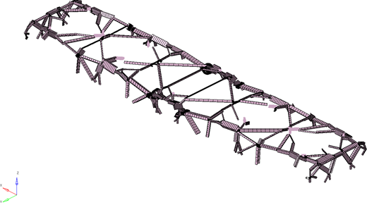
A load-bearing outer skin and an optimised arrangement of the compartments on the upper and lower decks result in a bundling of the load paths, thereby reducing the number of cross-beams required. The large and only lightly loaded areas between the beams that result from this can be replaced by lightweight materials (such as sandwich panels). The results of the topology optimisation are translated into practicable construction methods using a tool developed at the German Aerospace Centre (DLR) (see Figure 5) (Gomes Alves et al., 2022). To do this, the results of the topology optimisation are first converted into a wireframe model using a voxelisation approach, followed by skeletonisation and connection identification. The wireframe model can already be used as the basis for a parametric computer-aided design (CAD). In order to extrude beam sections along the wireframe axes, the geometric contour of a branch of the topology is first adapted to the basic shapes, such as a rectangle. These shapes are refined by identifying the load case of each branch. This is achieved by evaluating the stress distributions in the individual branches of the topology optimisation. The consolidated result can be further processed in a finite-element method or CAD application. In this way, a lightweight optimised structure can be pre-dimensioned at an early stage (Gomes Alves et al., 2022).
6.3 Design of a hybrid construction
The implementation of the above results in lightweight construction methods requires a structure that allows the use of a hybrid construction method. However, this application has its limitations. In areas that are too small and only exposed to low loads, sandwich materials, for example, increase the mass due to the necessary end profiles (Boese et al., 2025). Differential construction in combination with a hybrid construction method can resolve the various conflicting objectives when selecting materials for interior and structural components of rail vehicles.
A key aspect of this conflict is meeting the various requirements. On the one hand, safety and fire protection, and on the other hand, lightweight construction, stability and durability must be achieved using cost-effective materials and production methods wherever possible. The aim here is to avoid compromising on quality. In addition, the appearance and ergonomics of the components contribute significantly to passenger comfort and well-being. Environmentally friendly materials and recyclability are crucial for minimising the ecological footprint. However, this should only have a limited impact on maintenance costs and manufacturability. Therefore, a balance between manufacturing costs and operating costs must also be considered.
The use of hybrid construction methods allows these different requirements to be met in a targeted manner. Different materials and technologies are combined to utilise the best properties of each material and enable a balanced overall concept. Sleeping cars are subject to high fire-safety requirements. Among other things, it is not sufficient for the materials used to achieve fire safety class hazard level 3 according to EN 45545 (DIN, 2016). Each combination of materials used must also undergo a separate fire test for approval, and safety must be proven in each individual case. The project shows that multi-layer panels made of birch, poplar or albasia have proven to be particularly suitable as core material for interior use, but these must be clad on both sides with 1 mm aluminium sheet or steel sheet (Große et al., 2020). Aluminium honeycomb panels (6–10 mm thick, depending on the area of application) can also be used. For the interior surfaces, high-pressure laminate (HPL) with a minimum thickness of 1.2 mm, various coating systems or digital printing on both sides can be used, for example.
7. Conclusions
The ‘AliSa’ project shows that, due to the diverse requirements of users and operators, it is not sufficient to retrofit existing rolling stock. In order to enable economical and user-centred transport, the car body and the overall concept must be redesigned from scratch to allow for flexible operation. The developed car body allows for operator- and route-specific configuration of both the interior and the entire train set. The fixed coupling of three car bodies with two full levels increases passenger density and enables flexible and daily train composition. This allows both day and night trains to be operated economically. In contrast to previous night train concepts, this project considers the entire train formation with all necessary equipment (e.g. wet rooms and technical components) in order to create a concept that takes into account all needs, such as those of people with reduced mobility. The requirements for comfort, privacy and high passenger density result in a higher mass, which is compensated for in the ‘AliSa’ project by a lightweight optimised support structure. To this end, the potential of hybrid construction is being integrated.
Acknowledgements
The authors would like to thank the former Federal Ministry for Economic Affairs and Energy of the Federal Republic of Germany, for funding Project AliSa. Additionally, we extend our thanks to our consortia partners Olaf Schulz for initiating the project and his support, and to TRICON, k + v, GETA and SATEK for their collaboration and support. AI was utilized for language polishing in the preparation of this paper.

