One example of hydraulic structures which incorporate features involving air entrainment is the 'Muela station bypass which forms part of the Lesotho Highlands Water Project. The project's principal aim is to transfer water from Lesotho towards population centres in South Africa and it includes a high-level tunnel linked to a lower tunnel with 'Muela power station utilising the head difference between the two tunnels for power production. The station bypass has been designed to allow water to continue to be transferred if the station is out of operation, for example for maintenance.
The bypass, shown in diagrammatic section in Fig. 21, comprises
a 500 m long steel-lined tunnel 2·0 m in diameter
an enclosed energy dissipation structure
a covered concrete-lined chute generally 3 m wide, 3·5 m high and 350 m long, with a drop of 65 m
a stilling basin
an open channel 1070 m long, varying in width from 10 m to 15 m, falling 55 m and leading into 'Muela Reservoir.
The bypass is designed to discharge 32·6 m3/s under minimum operating level of 1989 m ASL. The sleeve valve which discharges into the dissipation structure, behind which are two air inlets, creates a considerable amount of spray which is suppressed by horizontal and vertical baffles inside the structure which is completely covered.
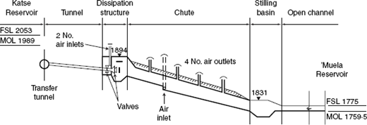
The velocity of the flow of water in the chute varies from approximately 7 m/s at the top to nearly 17 m/s at the entrance to the stilling basin. However, precautions were taken, following some helpful advice from Professor Ervine, to ensure that in addition to an air inlet in the invert, four air inlet outlets, 2 m in diameter, were provided in the soffit through the covers.
The form of the dissipation structure was the subject of a model test at a very early stage of the project development. The chute's dimensions were determined by mathematical analyses and computations. A series of tests were carried out at the commencement of operation to ensure that the bypass operated as designed.
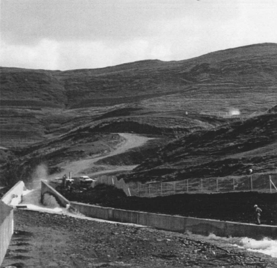
A view of the bypass is shown in Fig. 22 with spray emanating from the dissipation structure (which had not been covered at the time of the tests) in the upper right of the hillside, while the discharge from the stilling basin into the channel is evident in the foreground.
Author's reply
The author thanks the contributors for their short article on the 'Muela bypass, which is part of the Lesotho Highlands Water Project. The bypass illustrates well the various kinds of aeration that can occur in one structure, and which should be allowed for in the design process. The flow from the dissipation structure to the stilling basin has three different types of aeration
air dragged along near the soffit of the chute by the force of the flowing water; this is partly a boundary layer problem and also due to the air pressure difference from one end of the chute to the other
free surface aeration in the supercritical chute flow; this occurs when the water boundary layer reaches the free surface entraining air into the flow from the air above
plunge point aeration at the start of the hydraulic jump in the stilling basin; the original paper dealt with this type of aeration with suitable equations to estimate aeration rate.
In each case, entrainment of air into the flow, and the dragging of air with the flow, require air vents to prevent undesirable negative pressures and cavitation. Air vents are used both for air intake and escape and should be sized according to the expected air flows in the system. The expected air flows are difficult to determine without a physical model study. Certainly estimates of air flow dragged by the flowing water can be obtained from Falvey.22 Estimates of air inflow due to free surface aeration can be obtained from Ervine et al.23 and estimates of aeration into the jump downstream can be estimated from the author's paper under discussion. These will provide a broad-brush estimate of total air flow rate and will provide an indication of the size of air vents. A physical model study is still advisable. The physical model should have velocities greater than 6–7 m/s to avoid scale effects. If this means the model scale is uneconomically large, then a ‘slice’ model should be considered.