Type-120 relief valves are critical components of locomotive braking systems, and they rapidly discharge the air pressure during brake release to enable swift pressure relief. In order to develop type-120 relief valve rubber diaphragms with long life and high performance, the damaged faulty samples were analyzed and studied.
Finite element analysis (FEA) was used to investigate the stress distribution and failure mechanism of the rubber diaphragms within the type-120 relief valves under dynamic loading conditions. The Ogden hyperelastic constitutive model was used to fit the diaphragm data obtained from the uniaxial tensile tests, and its suitability for the modeling of large deformations was confirmed.
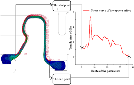
The FEA results indicated that, when the rubber diaphragms reached their maximum deformation, the peak stress on their upper surfaces was 5.44 MPa. Thus, this region is highly susceptible to fatigue damage. The service life of the rubber diaphragms could be extended by using rubber compounds with high tensile moduli or a fabric-reinforced rubber diaphragm.
This study provides valuable data and experience for the development of the rubber diaphragms in the type-120 valves and other long-life rubber products in the railway field.
1. Introduction
The type-120 control valves, which were developed in China, are air-brake control valves for locomotives and rolling stock. They can meet the braking requirements of heavy-load freight trains that operate on the railway network in China. This valve comprises four main components: an intermediate valve, a main valve, a semi-automatic pressure-relief valve (hereafter referred to as the type-120 relief valve), and an emergency valve (Gao et al., 2024). The type-120 relief valve releases compressed air from the brake cylinder to facilitate brake release in the event of a malfunction. Manual pulling of the type-120 relief-valve handle for 3–5 s causes air to be discharged from the brake cylinder until no air remains in the brake cylinder. Alternatively, the handle may be pulled continuously to fully release the compressed air from the entire braking system (i.e., the brake cylinder, the auxiliary air reservoir, the acceleration relief air cylinder, and the brake pipe).
The type-120 relief valve can be operated manually to release pressurized air from the brake cylinder, thereby enabling the brake mechanism to perform its relief function. It can also be used to exhaust pressurized air from the entire braking system. The rubber diaphragms within the type-120 relief valve are a critical component because they are responsible for both sealing the valve and transmitting mechanical loads. However, under complex loading conditions, the diaphragms are susceptible to rupture, which can compromise the performance of the braking system and potentially lead to safety incidents. Therefore, investigating the operational mechanisms of the rubber diaphragms and analyzing their fatigue and failure processes are important to enhancements in the reliability of rail-vehicle braking systems. The fatigue and wear resistances of the rubber diaphragms are key factors that directly affect the braking performance.
Due to its inherent high elasticity and low elastic modulus, rubber is susceptible to large elastic deformations under cyclic-loading conditions, and these large deformations may lead to permanent deformation and fatigue damage over time (Gao et al., 2023; Gehling, Schieppati, Balasooriya, Kerschbaumer, & Pinter, 2023; Le Gac, Arhant, Davies, & Muhr, 2015; Li et al., 2015). The use of high-modulus rubber compounds or fiber-reinforced rubber composites can effectively improve the performance and service lives of rubber components subjected to prolonged cyclic loading under constrained deformation conditions. High-modulus rubber formulations and embedded fiber reinforcements can enhance the mechanical strength, reduce the elastic deformation, and help maintain the dimensional and geometric stability of rubber (Gao et al., 2025; Li et al., 2020; Liu, Kadono, Yokoyama, Mayumi, & Ito, 2019; Liu et al., 2021).
2. Working principle and failure process of the rubber diaphragms
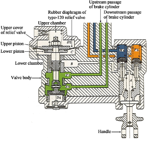
A schematic diagram of the type-120 relief valve is shown in Figure 1. When the manual relief is not implemented–that is, when the relief-valve handle has not been pulled–the type-120 relief valve remains in its initial position (non-operational) regardless of whether the type-120 control valve is in the pressurization and relief position, the deceleration pressurization and relief position, the normal braking position, the brake pressure-holding position, or the emergency braking position. In this state, the type-120 relief valve connects the upstream and downstream passages of the brake cylinder, functioning as a conduit for the flow of pressurized air without actively participating in pressure relief.
After braking, when the type-120 relief valve must release the brakes of a vehicle independently–that is, to discharge the pressurized air in the brake cylinder of that specific vehicle–the relief-valve handle can be pulled to initiate manual relief. At this point, one of two scenarios may occur. In the first scenario, braking conditions are present in which the decompression of the brake pipe exceeds the maximum effective decompression; thus, pulling the relief-valve handle causes the relief piston to become “locked” in the relief (upper) position. In this scenario, the relief valve isolates the upstream and downstream passages of the brake cylinder. The pressurized air from the brake cylinder reaches the relief valve through the downstream passage and is discharged through the exhaust pipe that is located beneath the relief-valve piston, while the pressurized air in the auxiliary air cylinder remains unaffected. The second scenario involves braking conditions in which the decompression of the brake pipe is less than or equal to the maximum effective decompression–that is, the main valve piston is in the brake pressure-holding position–so pulling the relief-valve handle does not cause the relief piston to be “locked” in the relief position. However, the main valve piston moves downward to the pressurization and relief position, thereby enabling the compressed air in the brake cylinder to be discharged through the exhaust pipe of the main valve.
Considering the various operating states of the type-120 relief valve and the levels of decompression in the brake pipe, the maximum pressure values in the lower and upper chambers of the type-120 relief valve, as well as the position of the relief piston rod, were recorded for each stage and are listed in Table 1.
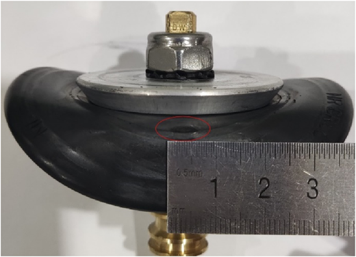
Figure 2 depicts a typical failure mode of the rubber diaphragms in the type-120 relief valves. The rupture occurred at the center of the diaphragm rather than at the inner and outer sealing ribs or at the transitional areas between the sealing ribs where structural changes occur.
3. Finite element simulation of the diaphragm's actions in type-120 relief valves
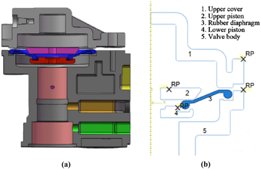
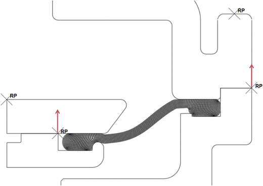
A three-dimensional diagram of the type-120 relief valves is presented in Figure 3 (a). This study focused on the rubber diaphragms within the type-120 relief valves. Given the axisymmetric nature of the diaphragm, an axisymmetric FEA model was created, as shown in Figure 3 (b). Since the deformation of the metal components was negligible compared to that of the rubber diaphragms, the metal components were modeled as rigid bodies, while the rubber diaphragms was modeled according to experimental data.
3.1 Modeling of the rubber diaphragms' rubber material
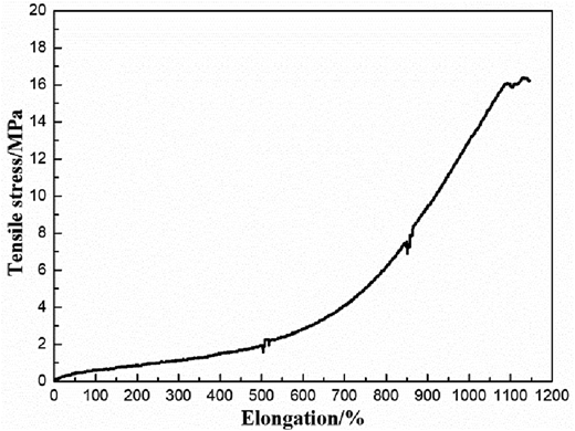
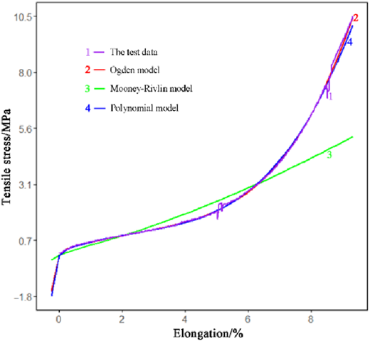
Rubber is a hyperelastic material that retains high tensile-strength values over a large strain range; this characteristic is essential to the long-term performance of the rubber diaphragms. To accurately characterize the mechanical behaviors of hyperelastic materials, it is generally necessary to obtain stress–strain data for a variety of loading types, such as uniaxial tension, biaxial tension, and planar tension. Then, the data must be fitted with appropriate constitutive models (Ostovar & Hejazi, 2025; Sylvain, Krmela, Pokorný, & Krmelová, 2024; Torggler et al., 2024). Since the primary focus of this study was on the deformation and stress states of the rubber diaphragms within the relief valve during operation, as well as the failure mechanism of the rubber diaphragms, only uniaxial tensile data were used (Figure 4). The tensile strength of the rubber diaphragms is 16.41 ± 0.42 MPa and its elongation at break is 1,146% ± 52%.
The commonly used constitutive models for rubber materials include the Ogden model, the Mooney-Rivlin model, and the Polynomial model (He et al., 2022). Of these, the Ogden model is particularly suitable for isotropic hyperelastic materials that undergo large deformations, and it can accurately represent the stress-strain relationships at high strain levels. The strain energy-density function of the Ogden model can be expressed by Equation (1):
Where , , and are the principal elongation ratios (i.e., the characteristic elongation ratios after deformation), and are material parameters that are determined by fitting experimental data, and N is the order of the model. To meet engineering accuracy requirements, the values of N must range from 1 to 3; in this study, N = 3.
The Ogden model is well-suited to materials that experience large strains, such as rubber. When appropriate adjustments are made to and , it can accurately capture the nonlinear behaviors of a variety of materials. When N = 1, this model can be approximated by the Neo-Hookean model (Ahmadi, Fathalilou, & Rezazadeh, 2024; Horgan, 2021; Kossa, Valentine, & McMeeking, 2023).
The Mooney-Rivlin model is another hyperelastic constitutive model that is often used to describe the mechanical behaviors of rubber materials. Its strain energy-density function is expressed in terms of the first and second strain invariants, and , according to Equation (2):
In Eq. (2), and are the first and second invariants of the isochoric strain, respectively; they can be expressed by Equation (3):
In addition, and are material parameters that are obtained through experimental fitting, and D controls the compressibility of the material.
When , the Mooney-Rivlin model reduces to the Neo-Hookean model (Ahmadi et al., 2024; Horgan, 2021; Kossa et al., 2023), which is suitable for rubber materials, such as tires and seals, that are subjected to moderate deformations. However, the Mooney-Rivlin model offers a greater accuracy over a broader strain range than does the Neo-Hookean model.
The Polynomial model, which is a high-order expansion that is based on and , is used to describe the complex deformation behaviors of hyperelastic materials. It can be expressed by Equation (4):
After adding a volume-change term, its full form can be expressed by Equation (5):
where is a material parameter that is determined through the fitting of experimental data, is a parameter that is related to the volume deformation and that is used to describe the volume changes of incompressible or compressible materials, and denotes the volume ratio.
The Polynomial model is a generalized form of the Mooney-Rivlin model. High-order terms can be selected as needed to improve its fitting accuracy. It is suitable for more complex rubber materials and biological tissues, especially those that experience large deformations. Adjustments can be made to i and j to accommodate different material properties. High-order models are associated with increased computational costs, however. As shown in Figure 5, the Ogden model best fit the test data that were obtained for the rubber material, while the Mooney–Rivlin and polynomial models exhibited larger deviations.
To accurately simulate the mechanical response of the rubber diaphragms in type-120 relief valves, a 3D FEA model was generated using the Abaqus software (Dassault Systèmes, Rhode Island, United States), and the axisymmetric quadrilateral element CAX4R was used to generate the model mesh. Reduced integration and hourglass control were used to effectively suppress zero-energy modes, thereby enhancing the simulation stability and convergence. This approach is well-suited for large-deformation analyses of rubber materials, and it can more accurately capture the nonlinear mechanical behaviors of the rubber diaphragms under complex loading conditions than existing approaches. Therefore, it provides reliable data for performance evaluations and structural optimizations of the rubber diaphragms.
3.2 Boundary conditions of the rubber diaphragms' actions in type-120 relief valves
Appropriate boundary conditions were selected for the model so it could simulate actual operating conditions using explicit dynamic analysis. The type-120 relief valve was assembled, and its upper and lower pistons, valve body, and upper cap clamped the rubber diaphragm so that a sealed state was achieved (Figure 6). The contact between the components was defined using the global contact method, and tangential contact behavior was modeled using the penalty method. The friction, which was set as isotropic and which was assigned a friction coefficient of 0.3, was not affected by the slip rate, the contact pressure, or the temperature. This configuration is suitable for simulations of the interactions between the rubber diaphragm and the surrounding structures because it effectively captures the frictional behavior and prevents excessive slippage at the contact interfaces.
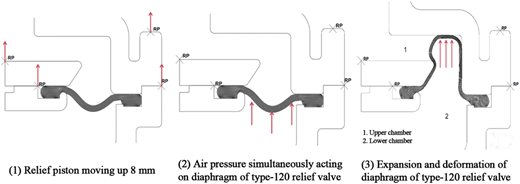
The upper and lower relief pistons ensure firm compression against the inner sealing ribs of the rubber diaphragm; thus, they maintain the seal and enable the piston rod to move upward under pressure. During the modeling process, the upper cap was fixed to the valve body, and equal-displacement boundary conditions were applied to the rubber diaphragm and the upper and lower relief pistons to simulate the upward motion of the piston rod. Figure 7 shows that, as the relief-valve handle is pulled, pressure acts on both the lower relief piston and the rubber diaphragm, thereby causing the relief piston to rapidly drive the piston rod upward and the rubber diaphragm to expand and deform (Wang et al., 2016; Xie, Li, Lai, Wu, & Zeng, 2015; Yagimli, Lion, & Abdelmoniem, 2024).
4. Finite element analysis results and discussion
The stress distributions of the rubber diaphragm in the type-120 relief valve were investigated for both the static state and action state using FEA.
4.1 Finite-element analysis of the rubber diaphragm in static state
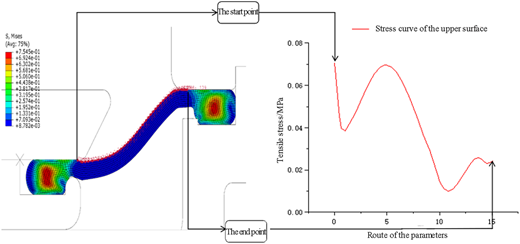
When the type-120 valve is in the pressurization and relief position, the deceleration pressurization and relief position, the normal braking position, or the emergency braking position, the rubber diaphragm in the type-120 relief valve remains in a static state. The Von Mises stress of the rubber diaphragm is shown in Figure 8 for each of these conditions. Since the force between the diaphragm and the upper piston is large, the principal stress distribution at the stress concentration point on the upper surface was extracted for analysis (Figure 9).
Figures 8 and 9 show that, in the static state, the maximum stress on the upper diaphragm surface is 0.07 MPa, while the maximum stress at the inner and outer sealing ribs is 0.75 MPa. The tensile strength of the rubber diaphragm is 16.41 MPa; thus, this strength is approximately 234 times greater than the maximum stress on the upper surface and 22 times greater than the maximum stress at the sealing ribs. These results indicate that failure of the rubber diaphragm is unlikely under static conditions (He et al., 2023; Zhang et al., 2020; Zulkefli & Gough, 2025).
4.2 Finite-element analysis of the rubber diaphragm during the action processes
When the relief-valve handle is pulled, the air pressure in the lower chamber of the relief valve rapidly increases to 0.47 MPa, and this pressure acts on both the lower relief piston and the rubber diaphragm. This process can be divided into two steps: first, the relief piston rod instantly moves upward by 8 mm, then the rubber diaphragm rapidly expands under the pressure.
4.2.1 Finite-element analysis of the rubber diaphragm with the piston rod moving up by 8 mm.
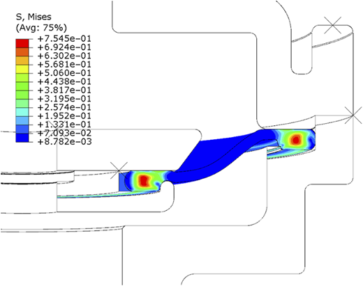
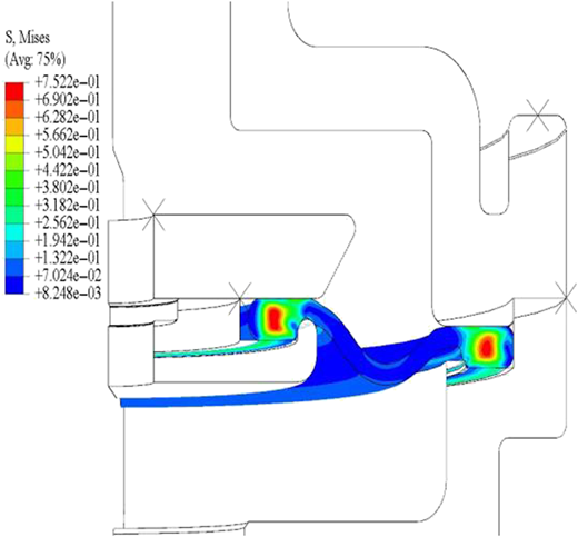
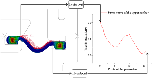
Figure 10 presents the Von Mises stress of the rubber diaphragm after the piston rod had moved upward by 8 mm. The principal stress at the stress concentration point on the upper surface of the rubber diaphragm is shown in Figure 11.
According to these results, the maximum stress on the upper diaphragm surface reached 0.23 MPa, while the maximum stress at the inner and outer sealing ribs was 0.75 MPa. The tensile strength of the rubber diaphragm (16.41 MPa) was approximately 71 times greater than the maximum stress on the upper surface and 22 times greater than the maximum stress at the sealing ribs. Therefore, the rubber diaphragm remains structurally intact when the piston rod moves upward by 8 mm (Michal, Martin, Marek, Petr, & Radek, 2024; Zulkefli & Gough, 2025).
4.2.2 Finite-element analysis of the rubber diaphragm with its maximum deformation.
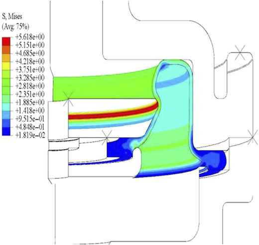
After the piston rod moves upward by 8 mm, the rubber diaphragm of the relief valve rapidly expands under the air pressure. The Von Mises stress at the point of maximum diaphragm deformation is shown in Figure 12, and the principal stress distribution at the stress concentration point on the upper surface of the rubber diaphragm is shown in Figure 13.
These results show that the maximum stress on the upper diaphragm surface reached 5.44 MPa, while the maximum stress at the inner and outer sealing ribs was 0.95 MPa. The tensile strength of the rubber diaphragm (16.41 MPa) was thus approximately 3 times the maximum stress on the upper surface and 17 times the maximum stress at the sealing ribs. The maximum-stress region shown in Figure 12 is therefore prone to fatigue damage; this conclusion is consistent with findings from fatigue testing and actual operations. Thus, after the rubber diaphragm expands, the contact area between the rubber diaphragm and the outer edge of the upper piston is particularly susceptible to damage and failure (Yu, Du, Zhang, Lin, & Zheng, 2013; Zine, Benseddiq, & Naiet Abdelaziz, 2011).
4.3 Comparison of the maximum stress values for the rubber diaphragm at different functional stages
The magnitude of stress directly affects the rate of internal damage accumulation and fatigue life of rubber materials, and high stress values can accelerate rubber fatigue failure. The stress state of the rubber diaphragm for type-120 relief valve is complex during use, and it is prone to fatigue damage. The maximum stress values of its upper surface and sealing ribs at various stages, such as the static state of the diaphragm, the moment when the piston moves up by 8 mm, and the maximum deformation of the diaphragm, are shown in Table 2.
Analysis shows that the inner and outer sealing ribs are in a static sealing state for a long time, and the maximum stress values at each stage are 0.75, 0.75, and 0.95 MPa, respectively. The maximum value only increases by about 27% compared to the minimum value, and the maximum value is about 0.06 times the tensile strength of the rubber material. Fatigue damage is not likely to occur here. The upper surface is in a dynamic sealing state, and the maximum stress values in each stage occur at different positions, namely 0.07, 0.23, and 5.44 MPa. The maximum value is about 77.71 times the minimum value, and the maximum value is about 0.33 times the tensile strength of the rubber material. The maximum stress position is prone to fatigue damage under dynamic load, which is consistent with the actual damage position of the diaphragm.
4.4 Optimization of the rubber diaphragm
It is evident from the analysis presented above that, at a certain point after the relief-valve handle is pulled, a localized region of the rubber diaphragm undergoes a sudden geometric change. This change leads to frictional contact between the upper diaphragm surface and the outer edge of the upper piston, which produces a stress concentration in this region. Under high-frequency dynamic loading conditions, this region experiences substantial cyclic stresses, and the resulting periodic stress concentration can induce fatigue, which can ultimately cause rupture failure of the rubber diaphragm.
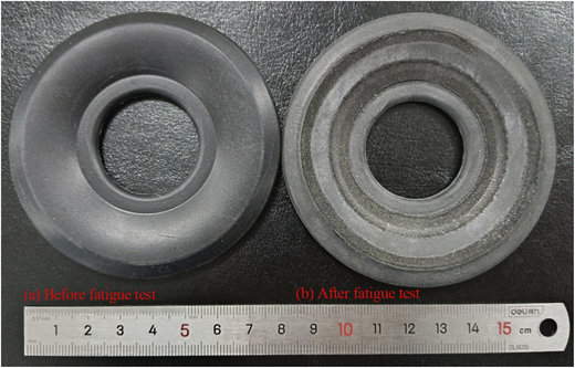
To address this problem, the extent of the geometric deformation and the contact conditions of the rubber diaphragm can be modified to reduce the stress on the upper surface of the diaphragm, thereby mitigating the stress concentration. Therefore, rubber compounds with high tensile moduli or rubber reinforced materials can be used to decrease the stress at the contact interface, thereby reducing the fatigue damage and failure probability of the rubber diaphragm, and ultimately extending its service life. The fatigue cycles of the prepared sandwich diaphragms (in Figure 14 a) for type-120 relief valves reached over 50,000 times, which were five times over the required cycles of them in TB/T 2206–2018 (National Railway Administration, 2019). The appearance of one sandwich diaphragm is shown in Figure 14 b, which has undergone 50,000 times fatigue test. It can be found that the wear position of it is consistent with the FEA results. According to the analysis of the sequential fatigue tests, the service life of the existing pure rubber diaphragms is one maintenance period (at least 24 months), and the corresponding service life of the sandwich diaphragms is 10 years.
5. Conclusions
During this study, an axisymmetric finite-element model of the type-120 relief valve was developed. In this model, the metal components were modeled as rigid bodies. The deformation and stress distribution of the rubber diaphragm were then analyzed. The Ogden model was used to fit uniaxial tensile test data of the rubber material after its suitability for large-deformation conditions was confirmed.
When the rubber diaphragm reached its maximum deformation, the stress on its upper surface reached its maximum value of 5.44 MPa. This peak-stress location is prone to fatigue damage, and this finding is consistent with observations gathered during fatigue testing and actual operations.
The service life of the rubber diaphragm can be extended by using rubber compounds with high tensile moduli or rubber reinforced materials.