Association of American railroads (AAR) standard automatic couplers are designed for much higher capacity than the normal operating loads. However, failure of knuckles and coupler bodies is still a common occurrence. Recent studies have shown that fatigue is the main reason behind such failures below the expected load. Moreover, knuckle failures occur more frequently than coupler body failures, which cause operational disruptions and also influence overall coupler life because of nonconforming contact between a new knuckle and an old coupler. In addition to new and old counterparts, undesired contact conditions are often the case with the new assembly due to casting-based manufacturing inaccuracies.
A study is thus carried out in this paper to understand the variation of load transfer paths and its consequences caused by dimensional variability. A finite element model of an E-type coupler's knuckle is developed and different possible contact conditions of the knuckle with the coupler head are simulated. Knuckles generally fail in pulling mode, during which the possible contacting elements of knuckle are pulling lugs, pin protector regions and pinholes. Due to dimensional variability, contact conditions may exist where an individual or a combination of these elements are in contact.
Simulation results indicate that under regular operational conditions, having only the pulling lugs in contact reduces the risk of knuckle failure and maintains assembly integrity even if the knuckle fails. However, under extreme loading conditions, the safest scenario is when both pulling lugs and pin protector regions are in contact.
These findings are believed to assist in defining the dimensional variability limits to ensure the desired contacts between the mating surfaces of the knuckle and coupler body of railway couplers of AAR type. This work contributes to understanding implications of dimensional variability in the railway couplers. The insight presented are useful in design, manufacturing and maintenance of railway coupler's knuckle.
1. Introduction
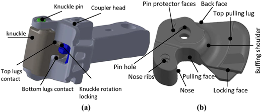
Association of American railroads (AAR) standard automatic coupler systems are widely used for interconnection of wagons in freight trains worldwide (Wagner, Cole, & Spiryagin, 2021). AAR coupler systems consist of an interconnection element called a coupler and an energy absorption element called a draft gear. Although an AAR coupler consists of several components, the major ones that are critical to coupling failure are the knuckle (Huang, Xia, Zhang, & Li, 2014; Shengyun et al., 2014), coupler body (Infante, Branco, Brito, & Morgado, 2003; Shengyun et al., 2014; Morgado, 2015; Yin et al., 2020) and lock. About 10–15% of knuckles are reported to fail early before two years of service period, while the service life of the entire coupler assembly is expected to be about six to seven years (Chunduru, Kim, & Mirman, 2011). The knuckles fail mainly during draft (or pulling) load. Figures 1a and 1b illustrate the critical interactions between coupler head and knuckle in a coupler assembly and address the vital nomenclature used in this paper.
AAR couplers require various slacks to facilitate the fitment of various components, interconnection of two coupler systems (Yadav & Vyas, 2023) and controlled starting dynamics of the train (Jackiewicz, 2021). These slacks play an essential role in achieving desired functionalities and in the life expectancy of the coupler system. However, due to the casting-based manufacturing process, controlling dimensional tolerances to the level to ensure the resulting slacks of the order of 1–3 mm is almost impossible. Therefore, desired slacks are never achieved between the components of newly assembled couplers (Carter & Gonzales, 2012). Also, interchanging coupler components is a common practice in the railway industry, resulting in the deviation of slacks (Gonzales, Carter, & Jones, 2010). Failed components are replaced by the same manufacturer or even by other manufacturers. The slacks between the knuckle and coupler body in the assembly result in impacts and frictional interactions, causing structural deterioration in the form of deformation, wear and cracks on contacting surfaces (Lee, Koo, Cho, Na, & Mun, 2018). Improper surface contact can lead to high localized stresses, promoting crack generation and propagation.
TTCI (Transportation Technology Center, Inc.) and other institutions have recently addressed the issues related to dimensional variabilities. Such a study by (Gonzales et al., 2010) shows that the interchanging coupler components of various manufacturers show fitment failure. Failure of individual components fitment result shows that occurrences of knuckle failure were highest, followed by lock and knuckle thrower. Another survey study on critical locations of failure of the coupler body and knuckle shows that the maximum failures occurred in knuckles due to the cracks on the pulling face, followed by cracks on the nose ribs and pulling lugs (Carter, Jones, & Gonzales, 2010).
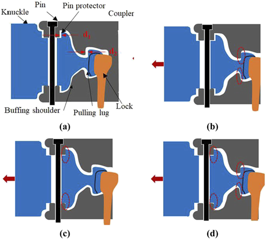
Some of their aspects on strength and fatigue life of coupler components have been introduced. However, a lot is required to solve the related challenges. For instance, an experimental test study was performed by (Carter & Gonzales, 2009) on the effects of misalignment in contacts between pulling lugs of knuckle and coupler head assembly due to dimensional variability. The results show that the stress levels in the knuckles exceeded the ultimate strength for the applied maximum load of 400,000 pounds (1780 kN) due to the misalignment. Even the misalignment of the order of 1 mm can increase the stress in the critical locations by about 40%. Also, the knuckle pin experiences significant stress even at a normal working range of 100,000 pounds (or 445 kN). A finite element analysis (FEA)-based study by (Gonzales & Carter, 2010) on the geometrical offset between an E-type coupler pin holes shows that such geometrical offsets lead to substantial loading on the pin and cause uneven contact of lugs, causing considerably different load distribution. (Sammon, Carter, & Jones, 2013) analyzed the variability in the dimensions of the type E coupler and its effect on the force transfer path by considering the only cases with extreme differences in the dimensions. Most of these studies have addressed the misaligned upper and lower counterparts of a particular feature well, for instance, pulling lugs and knuckle pin holes. The present study, however, introduces the effects when misalignments lead to the conditions when only pulling lugs are in contact or when only pin protector regions are in contact and the combinations of contact conditions, as shown in Figure 2. Misalignment between counterparts of individual features is not considered for the simplification of the study to focus mainly on the effects due to the presence and absence of contacts between various features.
Conventionally, the design basis for these couplers was based on the assumption that the coupler components fail mainly due to yield or ultimate strength (Chunduru et al., 2011; Hua, Wang, & Li, 2017; Lee et al., 2018; Tao et al., 2020). However, recent studies suggest that fatigue failure is the primary cause of the failure of coupler components, including knuckles (Daunys & Putnaitė, 2005; Song, Xie, Li, & Zhu, 2009; FRA, 2017; Li & Sun, 2020; Ren, Wu et al., 2022; Xiaochen, Tao et al., 2022), during normal operational conditions. Mostly, the ultimate strength requirement specified in Specification M-211 of the AAR Manual of Standards and Recommended Practices has been taken as design criteria. The frequent premature failures of knuckles have prompted the railway scientific community to consider fatigue failure a potential cause.
This study, therefore, takes into account the possibility of fatigue-based failure. Fatigue analysis has not been performed in this study, but the possibility of fatigue-induced failure has been assessed, considering the endurance limit of knuckle material under cyclic loading conditions. There has always been an ambiguity on the preferred contact of surfaces of the knuckle, coupler head and pin. Most FEA-based studies presume that all three types of contacts, i.e. between pulling lugs, pin protectors and pin-to-coupler bore, always exist (Carter & Gonzales, 2009; Chunduru et al., 2011; Lee et al., 2018). TTCI, however, believes that contact between pulling lugs only will be better for normal operational conditions. This study thus addresses the dimensional variability in contact conditions and gives an insight into preferred contact conditions, considering fatigue failure.
2. A real-life knuckle failure and measured dimensional variability
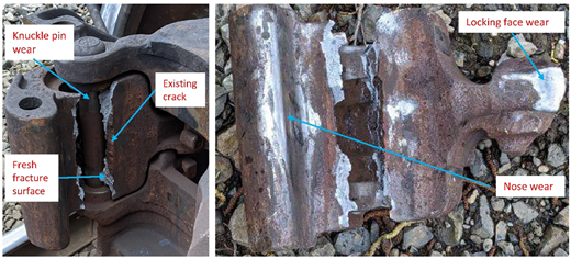
Figure 3 shows a real-world example of a broken coupler knuckle (source: Reddit, with permission) from the fifth car of an approximately 120-car coal train. Although the knuckle shown is of an F-type coupler, this study focuses on the E-type coupler, for which measurement data were available to develop the CAD model. The main differences between the two types lie in their contour geometry, contour slack and coupler tail, reflecting differences in application. However, the fundamental design, wear and tear behavior and failure patterns are largely similar. Such brittle fracture of pulling face is the most frequent failure mode of such knuckles; however, interested readers can refer to (Chunduru et al., 2011) for real-world examples of other possible failure locations.
A significant portion of the pulling face thickness is rusted, indicating the presence of a pre-existing crack that had gone unnoticed during inspections. Railway coupler systems are highly susceptible to corrosion fatigue cracks as they are continuously exposed to environmental conditions (Boelen, Curcio, Cowin, & Donnelly, 2004). As discussed in Section 1, fatigue failure of couplers and knuckles is common in modern railway operations. Corrosion fatigue is one of the major mechanisms contributing to such failures. Other common causes of knuckle failure include design-induced localized stress concentrations, casting defects and improper heat treatment practices (Huang et al., 2014). The presence of a fatigue crack at the pulling face suggests varying high-stress conditions. In addition to knuckle failure due to pulling face fracture, other operational defects observed in the presented coupler system include knuckle pin wear caused by rubbing with knuckle surfaces, locking face wear due to continuous contact with the coupler lock and nose wear resulting from continuous rubbing contact between the noses of mating knuckles. Dimensional variabilities resulting from manufacturing constraints and interchanging coupler components significantly alter the load transfer path and hence the differences in resulting stress distribution in the coupler and knuckle bodies. It is thus important to analyze possible dimensional variabilities to manage the stresses to mitigate such failures.
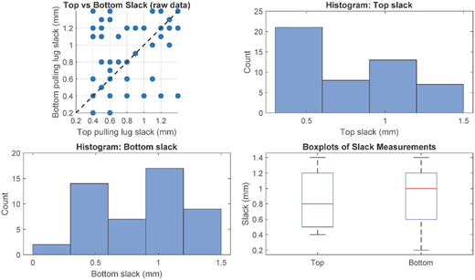
Statistics of a sample of 50 measurements of slacks between the top and bottom pulling lugs in the fully pushed condition of knuckle, in the assembled E-type coupler systems (to measure final slack in the assembly), provided by M/s Frontier Alloy Steels Ltd., Kanpur, is presented in Figure 4. The measurements were taken only for slacks between the knuckle and coupler pulling lugs; no slack was recorded at the coupler eye. It is assumed that the slack between the pin protector surfaces of the knuckle and coupler is always greater than that between the pulling lugs, meaning the initial contact under pulling conditions occurs at the lugs (as shown in Figure 2(b)). It is further considered that this remaining slack in the pin protector region is sufficient to accommodate lug deformation as the load increases, until at higher loads the slack closes and the pin protector regions also come into contact to share the load.
However, it is recommended that manufacturers conduct static tests on such couplers to determine the load at which contact initiates at the pin protector regions, following the initial contact between the pulling lugs. Recording both the remaining slack between the pin protector regions after the lug contact and the corresponding load at which pin protector contact begins would help define the desirable slack for ensuring knuckle safety.
The available measurement data, however, reveals a significant difference between the slack values at the top and bottom pulling lugs (Figure 4), which ideally should not exist. This suggests notable tolerance issues in the coupler and knuckle castings. As mentioned earlier, this difference has not been considered in the present study, and equal slacks at the top and bottom pulling lugs have been assumed. Similar discrepancies are also expected between the slacks at the top and bottom pin protectors.
Furthermore, the absence of measured slack data at the pin protector regions introduces additional uncertainty in assessing the system's performance. Therefore, it is recommended to measure the slacks at the pin protectors as well, perform corresponding static tests and carry out a statistical evaluation to define acceptable tolerance limits relative to the desired load level at which the pin protectors should engage. This forms part of the proposed future work.
3. Finite element modelling
An approximate CAD model of knuckle is developed with the help of visual inspection and manual measurements. Due to proprietary items, an exact CAD model could not be obtained. The model was validated by comparing the mass of the developed knuckle, which is 38.3 kg, falling in the 35–40 kg mass of actual knuckles. The coupler has not been modeled. Instead, contact conditions between the coupler and the knuckle are simulated using appropriate boundary conditions, where required. A three-dimensional CAD model of the knuckle is imported into finite element software ANSYS for static structural analysis. Pulling lugs, pin protector surfaces and pin holes are provided with appropriate boundary conditions to replicate their interaction with the coupler. Four extreme contact cases (1) pulling lugs alone (Figure 2 (b)), (2) pin protectors alone (Figure 2 (c)), (3) Pulling lugs and pin protectors (Figure 2 (d)) and (4) Pulling lugs, pin protectors and pin, are analyzed. The strength analysis of each case is investigated in-depth, and their effects on the structural strength of the knuckles are discussed.
3.1 Material model
The minimum required mechanical properties specified by Research Designs and Standards Organisation (RDSO), India, for casted couplers or knuckles using Grade E Steel are listed in Table 1.
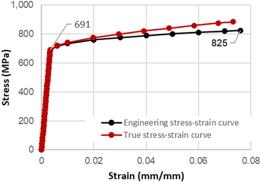
The minimum values of yield and tensile strength are chosen to keep a conservative approach, as listed in Table 1. In the absence of actual stress-strain characteristics, an approximate nonlinear elastoplastic material is modeled manually to consider the plasticity because knuckles and couplers are subjected to stresses beyond their yield strength, even in normal operating load conditions. Other mechanical properties, along with the elastoplastic material model required for FEA, are presented in Table 2 and Figure 5, respectively.
3.2 Boundary conditions
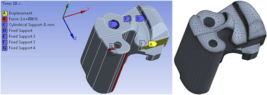
In the actual coupler assembly consisting of several components, the most relevant ones being the coupler body, knuckle and lock, frictional contact exists between the corresponding mating surfaces of two components. When the coupler body is not modeled, these contact conditions must be represented using appropriate boundary conditions. Thus, fixed supports are provided to the pulling lugs and pin protector surfaces because, once the knuckle is locked, the relative motions in all directions in these two mating regions are negligibly small. Fixed displacement condition has been applied normal to the locking surface to allow longitudinal motion while refraining the rotation of the knuckle. Cylindrical support has been provided on half the surfaces of the pinhole to represent the contact with the pin and tangential movement is kept free to allow rotation of the knuckle about the pin. Different initial contact conditions are incorporated for different simulation cases (Table 3).
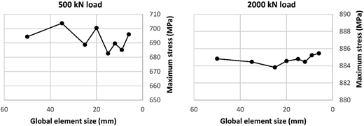
Figure 6 (a) shows the boundary conditions used in Case 4. Figure 6 (b) shows the meshing details. To simulate other cases, specific boundary conditions are removed. For example, in Case 1, boundary condition C (cylindrical support corresponding to pin contact) and boundary conditions F and G (fixed supports 3 and 4 corresponding to the upper and lower sides of the pin protector regions) are omitted. However, all other FEA modeling and simulation conditions remain unchanged. The initial mesh convergence study showed that the maximum stress value starts converging at a global element size of 15 mm. The knuckle has been meshed using a 12 mm global element size and is refined near the corners of the pulling lugs and eye sections.
Since this is a nonlinear analysis, involving stresses exceeding the yield strength even under normal operating conditions and containing small, sharp geometric features such as fillets and rapidly varying contours, the structural response is inherently nonlinear. Unlike in linear static problems, where stresses typically converge monotonically with mesh refinement, such direct convergence cannot be expected in nonlinear analyses. Therefore, a practical convergence criterion was decided: the global element size was considered acceptable when the difference in maximum stress between consecutive mesh sizes was less than 2%. Critical regions such as the pulling lugs, pin protector areas, locking face and pulling face, which are directly involved in load transfer and contact, were locally refined, while the rest of the knuckle body was meshed using a uniform global element size.
A mesh convergence study was conducted with global element sizes ranging from 6 mm to 50 mm (Table 4). Maximum von Mises stresses at 500 kN (normal operating load) and 2000 kN (extreme load) were used as indicators of convergence. As shown in Figure 7, there is no consistent monotonic trend of stress with mesh refinement due to the nonlinear behavior; however, the variation in maximum stress between 9 mm and 15 mm meshes is the smallest in the tested range for 500 kN load case. At extreme load of 2000 kN however, the max. stress varied between 884 and 886 MPa. Thus, mesh size is decided solely based on 500 kN load case. Based on this, the 12 mm mesh was selected as an optimal balance between numerical accuracy and computational efficiency. Compared with the finest mesh (6 mm), the peak von Mises stress at 500 kN varies by only ≈0.92%, while at 2000 kN it is essentially converged (≈0.11% difference). Thus, the 12 mm mesh provides a reliable and computationally efficient representation for both normal and extreme loading conditions.
E-type couplers are used in freight trains, and depending on the operational conditions, the operating load can generally be categorized into the following three loading regimes:
Cyclic loading during regular operation: The load range is 0–500 kN, and failure is governed by fatigue.
Non-cyclic loading during regular operation: The load range is 500–1,000 kN, and failure is governed by yield.
Non-cyclic abnormal loading: 1,000–1800 kN: Non-periodic, safety against tensile failure.
While in the first loading regime, operating loads are cyclic and need fatigue analysis simulations for more accurate results, fatigue analysis has not been performed, which is beyond the scope of this study. Instead, fatigue-induced failure possibilities have been assessed by checking the stress state above the endurance limit in the results of the static structural analysis. Since the first loading regime has also been assessed through static structural analysis, a static load of 2000 kN has been applied in 20 seconds, with a minimum of 10 load steps and a maximum of up to 100, to ensure convergence. The results are evaluated at the time steps of 5 s, 10 s and 20 s, corresponding to 500 kN, 1,000 kN and 2000 kN loads, respectively. The load between knuckles gets transferred through the knuckle nose.
4. Static analysis of knuckle strength
Analysis results reveal how dimensional variabilities lead to the variation of force transfer path, resulting in variation of maximum stresses and failure mode of the knuckle. Due to the complex three-dimensional geometry of the knuckles, with small features, there are always elements with high-stress concentration in FEA results. To deal with this issue, the knuckle geometry is often oversimplified, which is never close to reality. This study developed an approach to assess the results accurately without oversimplifying knuckle geometry. Irrespective of the maximum magnitude of stress, this study checks the significance of the volume of elements suffering from high stresses compared to the total volume of the knuckle. It also checks the extent of stretch of such elements in the zone of interest. The more the thickness or depth of the zone, under higher stresses, the more susceptible it is to failure. The results are capped at desired stress values to estimate the volume with stresses higher than the value of interest. Further, it should be noted that the conclusions drawn from the results consider the total affected volume and the extent of volume in particular locations of interest and the integrity of assembly after failure. Importance is given to overall safety rather than just the assessment of the strength of the knuckle. This study is thus intended to provide qualitative assessment rather than quantitative. Also, since this study does not use the knuckle model exactly the same as the initially manufactured knuckle and does not perform fatigue analysis, it is beyond the scope of this study.
4.1 Strength under cyclic loading during regular operation
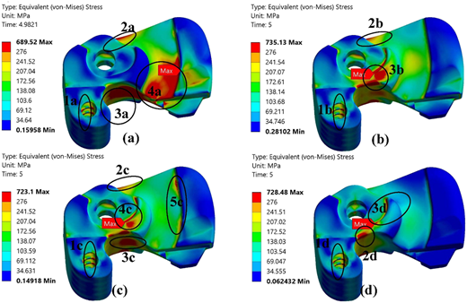
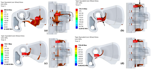
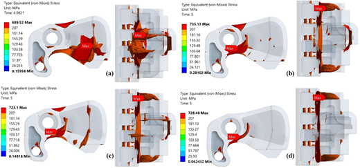
Depending on contact conditions, the load transfer path through knuckle volume changes and redistributes the maximum stress areas. Overall stress distribution under an applied static load of 500 kN has been presented in Figure 8. Corresponding capped iso-surfaces are presented in Figure 9 for an accurate assessment of affected zones and their importance in the strength of the knuckle against possible fatigue failure. Regions with stresses higher than assumed endurance strength, 0.4 × 690 (yield strength) = 276 MPa, are shown in Figure 8 for all four considered cases. Figure 9 (a) – 8 (d) present the volumes experiencing stress in the ranges of 276 MPa (endurance strength) to 689.52 MPa (the maximum stress in Case 1), 276 MPa to 735.13 MPa (the maximum stress in Case 2), 276 MPa to 723.1 MPa (the maximum stress in Case 3) and 276 MPa to 728.48 MPa (the maximum stress in Case 4), corresponding to the considered four cases at applied static load of 500 kN. Corresponding zones identified in case 1 (Figure 8 (a)) include the pulling face, corners of pulling lugs, back face and nose ribs, in the order of individual volumes subjected to the higher stresses, as seen in Figure 9 (a). The significantly affected zones in case 1 are pulling face and corners of pulling lugs. On the other hand, the zones identified with higher stresses in case 2 (Figure 8 (b)) include the pin protector region, nose ribs and back face, in the order of affected volumes (Figure 9 (b)). In this case, the significantly affected zone is the pulling protector region.
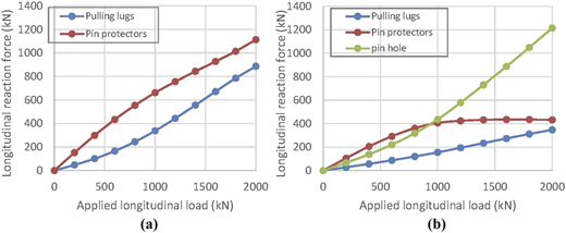
Since Case 3 combines the individual contact conditions in Case 1 and Case 2, the number of affected zones has increased. However, the affected volume of individual zones in Case 3, is lesser than in Case 1 and Case 2 due to more contacting surfaces sharing the total load (Figure 10 (a)). The most affected zone is still pin protector regions. Pulling lugs and pulling face have negligible affected volume compared to Case 1 because the load shared with pulling lugs is just about 125 kN out of the total external load of 500 kN (Figure 10 (a)). In Case 4, pin contact changes the load path remarkably. A significant load is shared by the pin (as shown in Figure 10 (b)), causing the maximum stresses to be confined to the pulling protector region, neighboring pulling face regions and nose ribs. In this case, the significantly affected zones are the pin protector region, followed by the pulling face. While the longitudinal load is shared between pulling lugs, pin protectors and pin, pulling lugs are not subjected to higher stresses due to further less sharing of the load on it (Figure 10 (b)).
The total volume in each case under the considered load has been presented in Table 5. It can be seen that the volume is decreasing with increasing numbers of contacts.
Although the affected total volume in Case 1 is the highest, however, if we compare Case 1 and Case 2 (Figure 9 (a), 9 (b)), it can be seen that in none of the critical regions (pulling face and pulling lug corners and) the higher stresses are extended to the whole thickness or depth. In contrast, in Case 2, it is extended to the full thickness and depth of the pin protector regions. Case 2 is, therefore, more prone to fatigue failure if there is any material defect. Even if pulling lugs get broken in case 1, the knuckle can sustain a longer life because of shifting the contact from pulling lugs to pin protector regions than the case when the pin protector region itself is damaged. A damaged pin protector region will lead to the load transfer to the pin and loss of locking, destroying the assembly's integrity and resulting in immediate abnormal and uncontrolled loading on components. In Case 3, although the affected proportion of thickness and depth in pin protector regions is slightly less, it is still significantly high. While the chances of knuckle failure in Case 3 are lesser than in Case 2, still, it is higher than in Case 1. Case 1 and case 4 are thus realized to be safer. Besides the least total volume affected by higher stresses and limited extension over the thickness and depth of identified zones, case 4 is critical because the pin is the weakest member in the assembly and will fail in shear. Also, the primary intended function of the knuckle pin is to facilitate the rotation of the knuckle around the coupler head during locking or unlocking and to provide assembly integrity. So, Case 1 is the preferred contact condition under cyclic loading with lower load amplitudes (up to 500 kN, in the considered case).
However, dimensional variability-induced slacks between the knuckle and coupler head may subject the pulling face cross-section to torsion, generating additional regions of high von Mises stress (not analyzed in this study due to limited scope). This torsional effect could further reduce the endurance ratio. Therefore, to illustrate the potential impact, the volumes exceeding a lower endurance strength threshold, taken as 0.3 × 690 MPa (yield strength) = 207 MPa, are also presented in Figure 11 to observe possible changes in the load transfer path.
It can be seen that, in the first three cases, the contribution of the back face to the high-stress regions has increased. Thus, at lower endurance strength (endurance ratio = 0.3), the knuckle may fail from both the pulling face and the back face simultaneously, leading to accelerated fracture compared to cases with higher endurance strength (endurance ratio = 0.4). Another notable difference is that at this lower endurance limit, the regions exceeding 207 MPa extend through nearly the full height of the pulling face, whereas previously they were confined to partial heights. This indicates that at lower endurance strength, the pulling face becomes more prone to fatigue failure, compared to higher endurance strength.
4.2 Strength under non-cyclic loadings
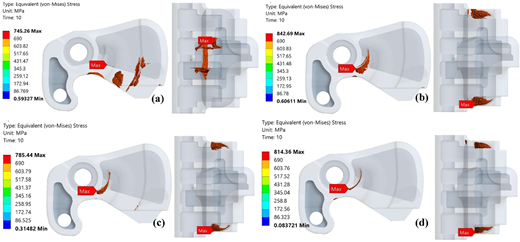
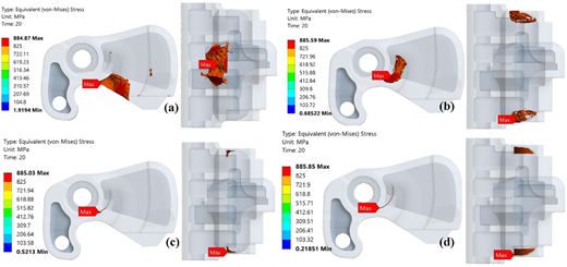
It is important to note that the railway coupler system is highly nonlinear and involves geometric, material and contact nonlinearities. Stresses can cross the yield point even under normal operational loads (0–1,000 kN). Thus, the stress distribution trend with increasing load will not be the same with just an increase in stress level, as is the case in linear systems. It is evident in Figures 12 and 13 that at larger loads (load = 1,000 kN (Figure 12) and 2000 kN (Figure 13)), the results are significantly different than those corresponding to cyclic conditions. As mentioned earlier, the strength of the knuckle for non-cyclic loading conditions has been assessed w.r.t. the yield strength and tensile strength for the loads of 1,000 kN and 2000 kN, respectively. The capped iso-surface results are generated with capping the stresses above 690 MPa and 825 MPa for 1,000 kN load and 2000 kN load, respectively.
It is seen in Figure 12 (a) that under normal running conditions, in Case 1, when the load magnitude is higher (1,000 kN) and non-cyclic, the zones with stresses higher than yield strength (690 MPa) are extended to minimal thickness and depth in the pulling lug corners and pulling face. The pin protector region in case 2, however, suffers from higher stresses to the full depth and thickness. The total affected volume is also higher for Case 2 compared to Case 1. Thickness in Case 3 and Case 4 decreased significantly; however, affected depth is still significant. In Cases 2, 3 and 4, the permanent deformation in pin protector regions will lead to pin contact and affect overall structural integrity. However, a permanent deformation in pulling lugs and pulling a face, in Case 1, will have no significant effects. Thus, in this loading condition also, the preferred contact condition is Case 1.
For a load of 2000 kN, it is evident from Figure 13 that Cases 3 and 4 have negligible volume affected by stresses higher than tensile strength. However, pin contact is not preferred because, as seen in Figure 10 (b), the reaction force on the pin increases rapidly after 1,000 kN, which will cause immediate failure of a pin. Thus, Case 4 is discarded from the choice, and Case 3 is preferred. Cases 1 and 2 are the worst cases, with a significant volume percentage with stresses larger than ultimate strength (Table 6).
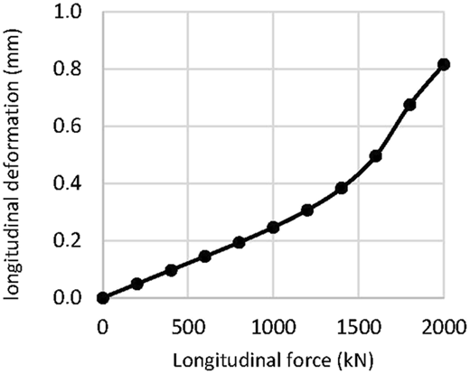
While the preferred case for loads 500 kN and 1,000 kN was Case 1, it can be converted into Case 3 for the loadings higher than 1,000 kN by the fact that the elastic deformation in pulling lugs should be close to the difference between longitudinal slack in pin protector regions and in pulling lugs of knuckle and coupler body. For instance, if the remaining slack in the pin protector surfaces between the knuckle and coupler head after the establishment of contact between pulling lugs was around 0.2 mm, pin protector regions will also be in contact once load magnitude reaches about 800 kN because the displacement of pin protector surface in the longitudinal direction is about 0.2 mm at an applied longitudinal load of 800 kN (Figure 14).
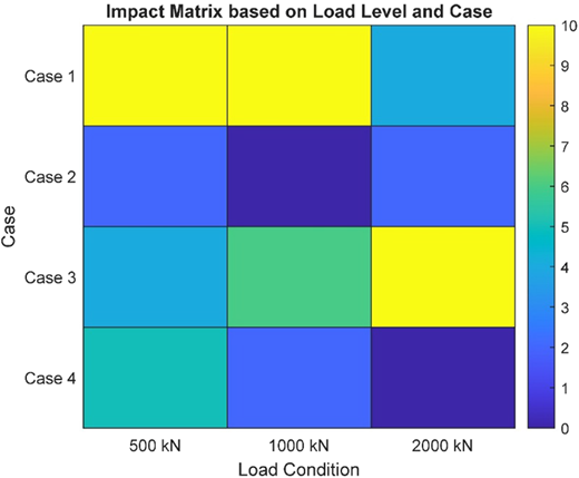
To visually realize the effectiveness of different loading cases on the knuckle, an impact matrix is presented in Figure 15, showing qualitative scores based on conclusions from the static analysis. Case 2, where initial contact occurs only between pin protectors, is the least favorable and should be avoided. Case 4 also shows below-average performance and is not recommended if alternatives exist. Case 1 achieved the highest overall score and is preferred for safety, followed by Case 3. The suitability of Case 1 is further supported by the fact that, under the initial pulling lug–only contact condition, it offers the highest safety during low-load cyclic operation. As the load increases and the pulling lugs deform, the pin protectors begin to engage and share the load, provided that the remaining slack between the pin protectors during the initial lug contact is not excessive. This allows Case 1 to gradually transition into a state similar to Case 3, which performs best under higher loading conditions.
5. Dynamic analysis of knuckle strength
While it was traditionally believed that static strength evaluation of the coupler system was sufficient to ensure safety, recent studies and field experience have shown that fatigue fracture is the dominant failure mode in couplers and knuckles. The previous section analyzed the knuckle's performance using static structural analysis for simplicity, with the results at a 500 kN load assessed against the endurance strength to identify regions prone to fatigue failure.
This section, further, examines the case of sudden impact loading (another dynamic condition, in addition to effects of cyclic load and fatigue failure), particularly during train start-up. Due to the presence of slack in the coupler system, the wagons immediately behind the locomotive begin to move while the remaining wagons are still stationary. As the coupler slack closes, the stationary wagons experience a rapid pull from the moving ones. The real-world knuckle failure presented in Section 2 occurred in a similar manner, according to personal communication with the user who posted the image (Figure 3) and initiated a public discussion on the Reddit community r/Justrolledintotheshop (Reddit, (Justrolledintotheshop, 2019). The failed knuckle belonged to the fifth wagon of a 120-car coal train and failed during train start-up on a flat track (zero gradient).
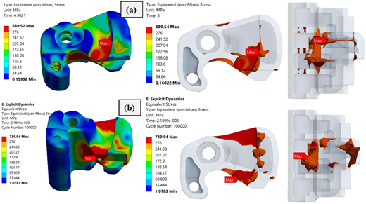
The explicit dynamic analysis was performed with a 500 kN load, a maximum simulation time of 3 ms, and a limit of 100,000 cycles, which was reached at 2.19 ms. The dynamic analysis results (Figure 16 (a)) are compared with those from the corresponding static analysis (Figure 16 (b)). The maximum stress location shifts from the pulling lugs to the pulling face, with the highest stresses distributed mainly along the pulling and back faces. Consequently, any defect in these high-stress regions, whether at the pulling face, back face or pulling lugs, can trigger a sudden fracture under impact loading.
These findings are consistent with the real-life failure case shown in Figure 3, where a pre-existing crack near the middle of the pulling face propagated rapidly under impact loading, leading to fracture. Furthermore, when analyzing the volume subjected to stresses above 276 MPa, it was found that in the static case the affected volume was approximately 98,224 mm3 (about 2% of the knuckle volume), whereas under dynamic loading it increased to 197,585 mm3 (about 4% of the volume); roughly twice as large. This demonstrates that dynamic impact loading produces substantially more severe stress conditions than static or low-frequency cyclic loading (typically in the range of 0–4 Hz (Uyulan & Arslan, 2020).).
6. Conclusions
While slacks in coupler design are intended to facilitate coupler connection and to ensure appropriate force transfer path, a significant deviation in slacks between surfaces of pulling lugs and pin protectors of knuckle and coupler body exist due to casted knuckle and coupler body assembly. Apart from the dimensional variability due to manufacturing limitations in the new coupler system, another source of such variability is the interchanging of coupler components of operational coupler systems. This study attempted to analyze the consequences of four types of contact conditions between knuckle and coupler head. It has been found that Case 1, when pulling lugs are only in contact, is the favorable contact condition for low-amplitude cyclic loadings. However, Case 3, in which pulling lugs and pin protector regions are in contact, is the best contact condition to sustain ultimate failure. A possibility of allowing slacks in the knuckle system has been discussed in which the contact condition remains as Case 1 for loads up to 800 kN, which then changes to Case 3. This study thus opens new paradigms to decide the best configuration for particular trains while considering fatigue failure.
While the scope of this study is limited, its foundational results lead to the following general recommendations.
Conduct static tests on multiple coupler assemblies with varying slacks at different contact surfaces to determine the load at which pin protector contact initiates after the initial contact between pulling lugs.
Manufacturers are recommended to measure the slacks at the pin protectors in addition to the current practice of measuring slacks only between the top and bottom pulling lugs.
Perform corresponding static tests and statistical evaluations to define acceptable tolerance limits relative to the desired load level at which the pin protectors should engage.
Maintain slacks within a tolerance range that allows initial contact between the pulling lugs, followed by gradual engagement of both pulling lugs and pin protectors, to ensure maximum safety of the coupler system.
Further studies should consider varying slack conditions at the top and bottom pulling lugs and pin protectors, along with more realistic loading scenarios beyond the purely longitudinal loads considered in the current study.
An analysis based on the entire coupler assembly, rather than just the knuckle, is recommended, as realistic boundary conditions can significantly affect load transfer paths and lead to more accurate results.
While numerous studies have addressed static and fatigue strength, impact loading scenarios in coupler systems are often underestimated. This study demonstrates notable shifts in stress distribution under such conditions, highlighting the importance of these analyses for ensuring coupler strength during train start-up.
The author sincerely thanks Mr. Tom Sharkey for permitting the use of his photographs originally shared on Reddit, as well as for the valuable technical discussions that provided important real-world insight into the engineering phenomenon discussed in this study. The author is also thankful to M/s Frontier Alloy Steels Ltd., Kanpur, for generously sharing the measured coupler slack data used in this research.