


Rail corrugation is still one of the unsolved challenges in the railway industry, and the abnormal vibration and high-frequency noise caused by it constitute serious adverse effects on the operating environment. How to control corrugation has been an important research theme, and understanding corrugation evolution features is the necessary prerequisite. This study aims to investigate the specific evolution characteristics of corrugation from the contact stick-slip perspective.
The formation and development processes of corrugation are analyzed by using a self-designed scale-down test device. Specifically, the contact stick-slip characteristics under different creepage conditions are analyzed and the formation mechanism of corrugation is summarized. On the basis of corrugation formation, the trend of corrugation development is further emphasized to completely describe the whole process of corrugation evolution.
The results show that, under the determined vertical load condition, the contact interface appears the creep force-creepage negative slope phenomenon in the transverse direction. The cause of short-pitch corrugation on the rail wheel surface under the smaller angles of attack may be related to the inherent vibration frequency of the test device, and the cause of corrugation on the rail wheel surface under the larger angles of attack is mainly related to the stick-slip vibration induced by contact creep saturation.
This research explores the evolution characteristics of corrugation by adopting a self-designed scale-down test device, and elucidates the mechanism of corrugation in detail.
1. Introduction
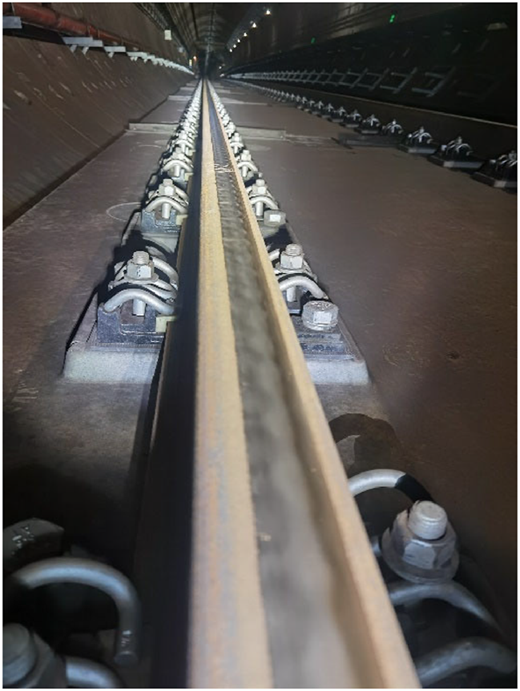
Corrugation is a periodic wave-like wear appearing on the rail surface, as shown in Figure 1, commonly found on urban rail transit lines. Affected by line operating conditions, corrugation forms vary in the performance, and corrugation for a long time has not been effectively managed. Unlike the even wear, corrugation destroys the continuity of the contact surface, thus easily inducing abnormal vibration and high-frequency noise in the wheel-rail system and may lead to fatigue failure of related components, so the control of corrugation is crucial to ensure the normal operation of the rail transit system (Ling et al., 2017; Wei, Sun, Zeng, & Qu, 2022; Cui et al., 2023). Typically, most corrugation occurs on small curve tracks with the radius below 350 m, and the occurrence probability of corrugation on these types of tracks is close to 100% (Mei & Chen, 2023). In addition, in the straight track, corrugation also has the possibility to occur and is generally presented as short-pitch corrugation, which is mainly associated with the specific track structures (Zhang, Liu, Liu, & Wu, 2014; Liu, Zhang, Liu, & Thompson, 2018). How to eradicate the problem of corrugation has always been an important issue in the rail industry, and understanding the evolution of corrugation is very useful for achieving effective control of corrugation.
Research on the problem of corrugation has been going on for more than a hundred years now, and corrugation is still one of the hot topics of interest in the industry. Although many scholars have not yet reached a consensus on the mechanism of corrugation, the relevant achievements have contributed to the improvement of the theoretical framework of corrugation, which also indicates the uncertainty of causes of corrugation, that is the formation process of corrugation is subject to a variety of factors. The theory of the friction self-excited vibration (Chen et al., 2010, Chen et al., 2014) can well explain most corrugation phenomena, and it can accurately predict the occurrence frequency and location of corrugation. There are also some evidences that the above theory can be used as a validation benchmark for rail corrugation prediction models (Chen & Feng, 2025; Cui et al., 2025; Li et al., 2025; Zhang et al., 2025). Resonance theory (Li et al., 2016; Guan, Liu, Wen, & Jin, 2024) is one of the classical theories explaining the formation and development of corrugation, which suggests that the excitation of the inherent property of the system is the main cause for inducing corrugation. The stick-slip theory (Wang & Lei, 2023; Sun & Simson, 2008) examines the evolution of corrugation from the wheel-rail micro contact level and considers the system’s macro vibration characteristics. Corrugation, although it is subject to different formation mechanisms, can still be described using the wavelength and wave depth, reflecting a certain similarity in the evolution of corrugation.
Field research allows direct access to characteristic data of corrugation, however it is not easy to monitor the evolution of corrugation during a grinding cycle, due to the short skylight period of rail transit and limited access to the field. In order to portray the whole evolution of corrugation in detail, indoor tests have gradually become an alternative to corrugation studies, including full-scale and scale-down tests (Naeimi, Li, Petrov, Sietsma, & Dollevoet, 2018; Zhang & Li, 2023; Buckley-Johnstone, Harmon, Lewis, Hardwick, & Stock, 2019; Bellette, Meehan, & Daniel, 2011; Jin & Wen, 2007). Indoor tests are easily operated and there is no time limit on the use, making them suitable for investigating problems of corrugation evolution that require a certain amount of time. Although the indoor tests are simplified relative to the field situation, they are able to approximate the characterization of the material wear trend, that is the corrugation evolution trend.
The adverse effects and obstinate characteristics of corrugation phenomenon make the research of corrugation still necessary and urgent, in view of such, this paper mainly adopts self-designed scale-down test device to explore the evolution characteristics of corrugation, so as to elucidate the mechanism of corrugation and control the development of corrugation. Firstly, the composition and function of the self-designed scale-down test device are introduced, and its stability is calibrated. Then, using the test device, the contact stick-slip characteristics under different creepage conditions are analyzed and the formation mechanism of corrugation is summarized. Finally, on the basis of corrugation formation, the trend of corrugation development is further emphasized to completely describe the whole process of corrugation evolution.
2. Test device
2.1 Composition and function
The test device established in this paper is a scale-down twin-disc test rig, as shown in Figure 2. The test device consists of three main parts: the superstructure, the substructure and the support structure. The superstructure includes angle adjustment device, loading device, vertical force sensor, deep groove ball bearing, top plate, upper end cover, lower end cover, wheel and axle and tachometer. The substructure includes motor, frequency converter, coupling, rail wheel and axle, thrust ball bearing, transverse force sensor, baffle plate, sensor digital display meter. The support structure includes base plate and brackets. The angle adjustment device consists of a rotating disc and an upper end cover connected thereto, and the upper end cover is connected to the lower end cover via two positioning axles. The loading device consists mainly of a steel spring with a wire diameter of 10 mm, a spring diameter of 55 mm, a spring length of 120 mm and an effective number of 8 coils. The motor type is a three-phase 750 W horizontal gear motor, with type 50 shaft diameter, 1/3 reduction ratio, 470 r/min output and three-phase 380 V voltage. The frequency converter matched with the motor has a power of 750 W and a single-phase voltage of 220 V. The vertical/transverse force sensor and deep groove/thrust ball bearing are all standard parts.
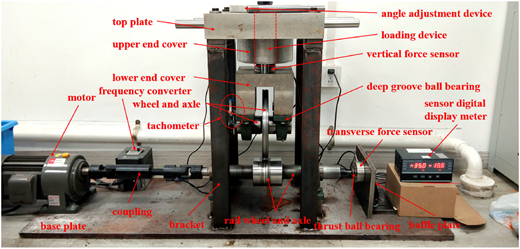
The wheel radius in the test device is 105 mm, compared to the nominal rolling circle radius of 420 mm of the actual metro vehicle wheel, the scaling factor is 1/4. The wheel and axle material is CL60 steel, and the rail wheel and axle material is U71Mn hot-rolled steel, whose chemical compositions and hardness are shown in Table 1 (Zhang et al., 2023; Li, Xu, & Deng, 2024; Chen, Yuan, Li, & Yang, 2024; Wang, Wu, & Ma, 2024; Gao, Liu, Gu, & Zeng, 2024). In order to reduce the device weight for easy installation, the upper end cover, lower end cover and top plate are all made of aluminum alloy. In the meantime, in order to improve the stability of the device, the bottom plate is made of steel plate with a thickness of 20 mm for support, and the bracket is made of 50×50 mm square steel pipe with a thickness of 5 mm. In addition, it should be noted that the design of wheel and rail wheel in the test device is mainly scaled based on the geometry and resonance frequency of the actual wheel and rail, and the modal analysis is performed (Yao, Shen, & Gao, 2018). The resonance frequency of the designed wheel is as close as possible to that of the actual wheel after scaling, and the wheel is not deformed too much under the condition of ensuring the maximum applied pressure, while the design of the rail wheel is based on the resonance frequency as large as possible after scaling, which is more than three times of the resonance frequency of the wheel to design.
Chemical compositions and hardness of wheel and rail wheel materials
| Item | Material | Chemical composition (%) | Hardness (HV0.2) | ||||
|---|---|---|---|---|---|---|---|
| C | Si | Mn | P | S | |||
| Wheel and axle | CL60 | 0.57–0.67 | 0.15–1.00 | 0.60–0.90 | 0.030 | 0.005–0.040 | 331 ± 11 |
| Rail wheel and axle | U71Mn | 0.65–0.76 | 0.15–0.58 | 0.70–1.20 | ≤0.030 | ≤0.025 | 288 ± 10 |
Source(s): Authors’ own work
The test device established in this paper is easy to install, and it can realize the precise control of the rotation angle of the superstructure, loading amplitude and motor speed. The test purpose of the device is focused on the wheel–rail wheel contact interface, with specific functional features: (1) Simulation of the wear process of wheel/rail wheel surface material, including the evolution of corrugation; (2) Study of the rolling contact fatigue (RCF) phenomenon on contact surfaces; (3) Analysis of the matching effect of different wheel and rail wheel materials and (4) Study of the action mechanisms of third media (e.g. water, lubricants, leaves, friction modifiers, etc.); at the contact interface on surface damages. In addition, the radius dimensions of wheel and rail wheel can also be adjusted to take into account the influence of the scaling effect on the test results.
2.2 Stability analysis
The stability of the test device determines the reliability of the test results, therefore, it is necessary to calibrate the stability of the test device. By modulating the rotating disc of the angle adjustment device, the angle of attack between the wheel and the rail wheel is set to 0°. The vertical load is set to 800 N, and the running frequency of the rail wheel is set to 160 r/min. The test device is then activated and the vertical and transverse force indications are recorded. The above test procedure is repeated three times with a duration of 10 min each time, that is the rail wheel is running for a total of 1,600 r in a single run. By averaging the data from three tests, the vertical and transverse force variation curves can be obtained, as shown in Figure 3.
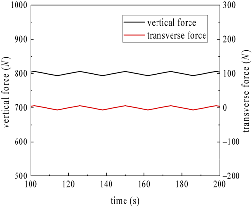
As can be seen from Figure 3, when the rail wheel is running, the vertical force varies in the range of 794–806 N, and the transverse force varies in the range of -5-5 N, with fluctuations below 15 N. Compared to the vertical load of 800 N, the fluctuation amplitudes of the above forces are relatively small (<2%), and therefore the test device is relatively stable.
3. Contact stick-slip characteristics – mechanism of corrugation formation
Based on the established test device, the stick-slip characteristics of the wheel-rail wheel contact interface are emphasized in this section, thus attempting to explain the corrugation formation mechanism from the contact stick-slip point of view. As can be seen from Figure 2, the test device has only one motor and is connected to the rail wheel axle, that is the rail wheel is the active one and the wheel is the passive one. Therefore, in the ideal case, no longitudinal creep force is generated at the wheel-rail wheel contact interface. By setting the angle adjustment device, the contact angle of attack between the wheel and the rail wheel can be changed, whereby a transverse creep force will be generated at the contact interface. From the above, it can be concluded that the test device can simulate the conditions of pure rolling and the presence of transverse creep force. In this section, the stick-slip characteristics of wheel-rail wheel contact under different conditions of transverse creepages are analyzed, which correspond to some extent to the wheel-rail contact characteristics on curve lines (different angles of attack correspond to wheel-rail contact relationships on lines with different curve radii).
Set the angle of attack between the wheel and the rail wheel to 0°, the vertical load to 800 N, and the running frequency of the rail wheel to 160 r/min, and then start the test device for the test. After 10 min of operation, the angle of attack is increased to 0.5° and the device continues running for another 10 min. The above steps are repeated until the angle of attack is increased to 6° to end this set of tests. Afterwards, the second and third sets of comparison tests are conducted by varying the vertical loads to 600 N and 1000 N, respectively. The variation curves of transverse creep force-transverse creepage (angle of attack) under different vertical loads are shown in Figure 4.
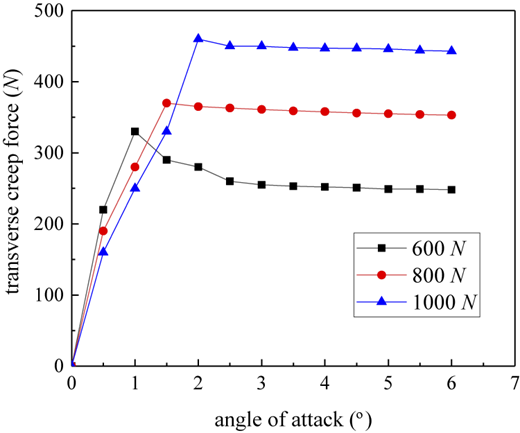
The variation of angle of attack in Figure 4 can represent the variation of transverse creepage, and the transverse creep force is approximated by the transverse force instead. As can be seen from Figure 4, for a determined vertical load, the transverse creep force first increases rapidly to a peak value as the angle of attack increases, and then gradually decreases and tends to be constant. This process indicates that the contact interface appears to have a negative slope phenomenon of creep force-creepage in the transverse direction, and the contact area will undergo a transition of adhesion, stick-slip and slip with the increase of creepage. Therefore, when the creepage reaches or exceeds the critical value (corresponding to the peak creep force, i.e. the saturated creepage), the contact interface will generate stick-slip vibration, which may induce the formation of surface corrugation. Moreover, it can be seen from Figure 4 that the slope of the initial segment of the transverse creep force-angle of attack curve gradually decreases with the increase of the vertical load, while the peak transverse creep force gradually increases, suggesting that the larger vertical load requires a larger saturated creepage.
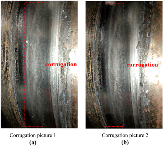
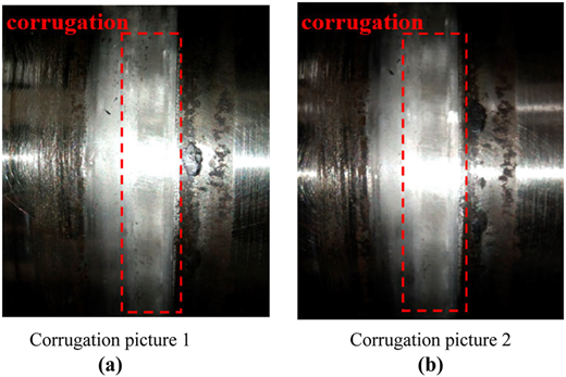
According to the test results in Figure 4, the vertical load of 800 N is taken as an example, the running frequency of the rail wheel is set to 160 r/min, and the angles of attack between the wheel and the rail wheel are respectively 0.5°, 1°, 1.5° and 2°, corresponding to the transition interval from the positive slope to the negative slope of the transverse creep force-angle of attack curve, which are recorded as conditions 1–4. Then the test device is started to conduct the test, and the running time is set to 12 h. After the test is completed, the test results corresponding to conditions 1–4 are shown in Figures 5–8.
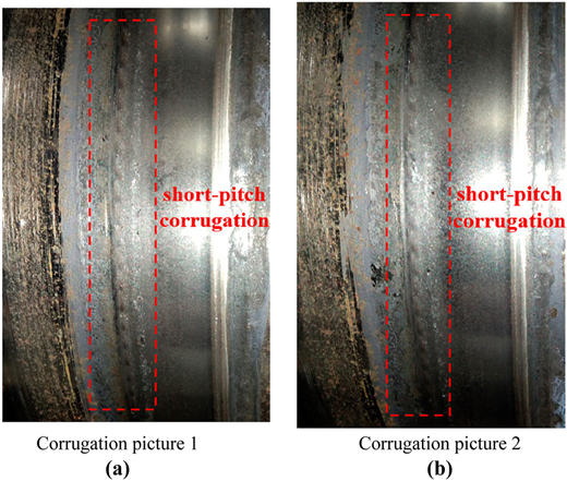
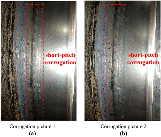
From Figure 5, it can be seen that under the condition of angle of attack of 0.5°, when the rail wheel runs for 12 h, the rail wheel surface shows obvious continuous short-pitch corrugation. Similarly, from Figure 6, it can be seen that under the condition of angle of attack of 1° and 12 h operation of the rail wheel, the rail wheel surface also shows obvious continuous short-pitch corrugation, and it is similar to the short-pitch corrugation shown in Figure 5, only the wave depth of corrugation has been increased. According to Figure 4, it is easy to find that for the transverse creep force-angle of attack curve with a vertical load of 800 N, the transverse creep forces corresponding to angles of attack of 0.5° and 1° are in the positive slope segment of the curve, and it is relatively difficult for stick-slip vibration to occur under the normal condition. Therefore, the cause of surface corrugation of the rail wheel in conditions 1 and 2 has little to do with the stick-slip vibration of the contact interface, and may be related to the inherent vibration frequency of the test device. Setting the diameter of the rail wheel in the test device as gives its circumference as:
Further, according to the rail wheel running frequency , the rail wheel running speed is obtained as:
Substituting mm and r/min into Equations (1) and (2) gives as 837.76 mm/s. The corrugation wavelength in Figures 5 and 6 is about 3–4 mm, according to the frequency calculation formula (3):
it can be obtained that the corrugation passing frequency in Figures 5 and 6 is about 209.44–279.25 Hz.
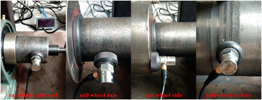
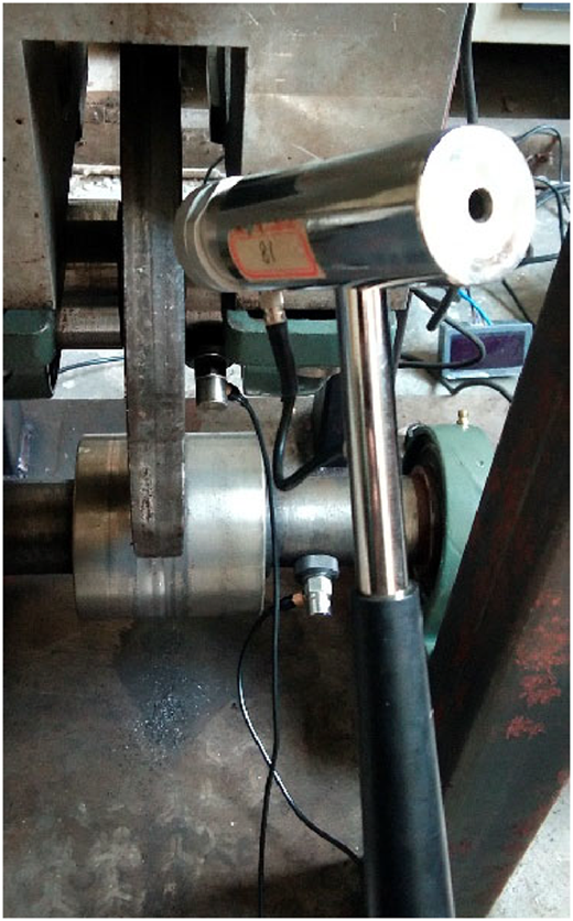
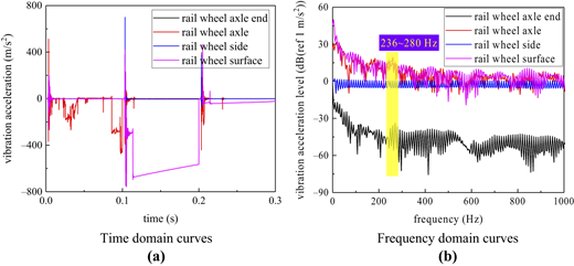
In order to determine whether the above corrugation passing frequency correlates with the inherent property of the test device, a hammering test is carried out on the test device. The frequency response characteristics of the test device are tested using the force hammer percussion method, with a total of three groups of tests, each group of tests totaling three percussions, and the average of the test data is taken to eliminate testing errors. The sensors are arranged at the rail wheel axle end, rail wheel axle, rail wheel side and rail wheel surface as shown in Figure 9, and then the rail wheel is percussed using a force hammer with a steel hammer head to obtain the corresponding frequency response results. The acceleration sensor type is internal IC piezoelectric acceleration sensor, with the model number LC0152; the model number of the signal acquisition analyzer is INV3062T0 and the model number of the force hammer is YD-5T 140,325, as shown in Figure 10. The test results are shown in Figure 11, including time and frequency domain curves. As can be seen from Figure 11, the vibration acceleration levels of rail wheel axle end, rail wheel axle and rail wheel surface have peaked in the range of 236–280 Hz, and the vibration acceleration level of rail wheel side has not changed significantly, which may be related to the percussion direction of the force hammer (in this paper, the hammer percussion direction is in the radial direction of the rail wheel, thus not easy to cause obvious changes in the vibration of the rail wheel side.). The results of the hammering test indicate that the inherent vibration characteristics of the test device in the range of 236–280 Hz may be the main cause of corrugation with a wavelength of 3–4 mm on the rail wheel surface.
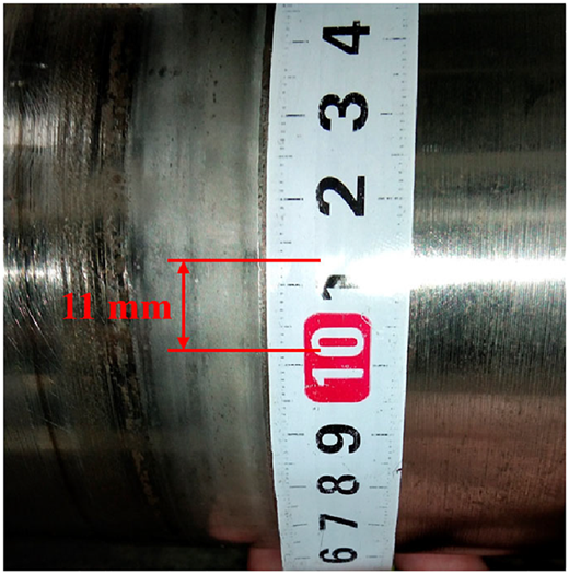
As can be seen in Figures 7 and 8, at the angles of attack of 1.5° and 2°, the surface of the rail wheel after the completion of the test also shows the phenomenon of corrugation, but the corrugation wavelength is longer than that shown in Figures 5 and 6, about 11 mm (corresponding to the corrugation passing frequency of about 76.16 Hz), as shown in Figure 12. This indicates that the corrugation formation mechanism in Figures 7 and 8 is different from that in Figures 5 and 6. According to Figure 4, it can be seen that the contact angles of attack of 1.5° and 2° in conditions 3 and 4 have reached and exceeded the critical value, and at this time, the contact interface is very prone to generate stick-slip vibration, which in turn promotes the formation of corrugation. Because the corrugation form in conditions 3 and 4 is transformed relative to the form in conditions 1 and 2, and the transverse creepage has reached and exceeded the saturation value, thus the cause of the surface corrugation of the rail wheel in conditions 3 and 4 is mainly related to the stick-slip vibration caused by the saturation of the contact creepage.
4. Corrugation development characteristics
On the basis of the formation of corrugation, the developmental characteristics of corrugation are further analyzed in this section. Since corrugation has the wavelength-fixed property (Grassie & Kalousek, 1993; Grassie, 2009) under constant system operating conditions, therefore, the corrugation development test is carried out in this section using condition 4 instead. Keeping the running condition and wheel/rail wheel specimen of condition 4 unchanged, and then the test device is started to continue the test, and the running duration is set to 2×12 h, that is recorded once every 12 h of running. The pictures of the rail wheel surface after the completion of the test are shown in Figure 13.
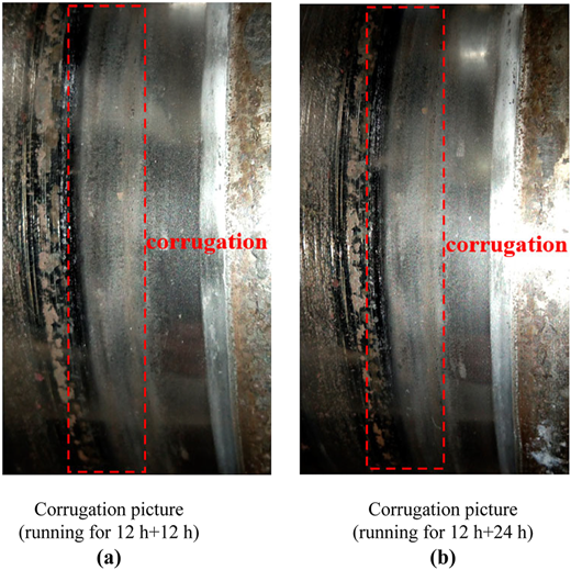
As can be seen in Figure 13, the surface corrugation wavelength hardly changes with the increase of the rail wheel running time, while the wave depth tends to increase in general. Specifically, after 12 h of running of the rail wheel containing the initial corrugation, the corrugation wave depth increases significantly, as shown in Figure 13(a), where the dark area is the trough and the bright area is the peak. After 24 h of running of the rail wheel containing the initial corrugation, the corrugation distribution is shown in Figure 13(b). Compared with Figure 13(a), the corrugation wave depth in Figure 13(b) does not change much, which indicates that the growth of corrugation tends to slow down in the running period of 12–24 h of the rail wheel containing the initial corrugation. Combining Figures 8 and 13, the corrugation evolution process can be described as three stages: the initial corrugation formation process, the middle corrugation development process and the late corrugation stabilization process. It should be clarified that the running time in Figure 13 is the total running time of the rail wheel, that is it includes the 12 h running time of the rail wheel corresponding to the initial corrugation formation process.
5. Summary
In this paper, the corrugation evolution is investigated from the contact stick-slip point of view using a self-designed scale-down test device. By analyzing the stick-slip features of the contact interface under different creepages, the formation mechanism of corrugation is explained, and based on the formation of corrugation, the development characteristics of corrugation are further analyzed. The main conclusions are as follows:
Under the condition of constant vertical load, with the increase of angle of attack, the transverse creep force firstly increases rapidly to the peak value, and then gradually decreases and tends to be constant, indicating that the phenomenon of negative slope of creep force-creepage occurs in the transverse direction at the contact interface. With the increase of vertical load, the slope of the initial segment of the transverse creep force-angle of attack curve gradually decreases, while the peak transverse creep force gradually increases, indicating that the larger vertical load requires a larger saturated creepage.
The transverse creep forces corresponding to angles of attack of 0.5° and 1° are in the positive slope segment of the transverse creep force-angle of attack curve, which makes it more difficult for stick-slip vibration to occur. Therefore, the cause of the surface corrugation of the rail wheel at the above angles of attack may be related to the inherent vibration frequency of the test device, and the characteristic frequency is about 209.44–279.25 Hz.
The transverse creep forces corresponding to angles of attack of 1.5° and 2° are in the negative slope segment of the transverse creep force-angle of attack curve, which is very susceptible to stick-slip vibration. Therefore, the cause of the surface corrugation of the rail wheel at the above angles of attack is mainly related to the stick-slip vibration induced by the contact creep saturation, and the characteristic frequency is about 76.16 Hz.
With the increase of the rail wheel running time, the surface corrugation wavelength hardly changes, while the wave depth tends to increase in general. The evolution process of corrugation can be approximately divided into three stages: the initial corrugation formation process, the middle corrugation development process and the late corrugation stabilization process.
The conclusions drawn in this research are based on the scale-down test, which has yet to be verified for the reasonableness. In the next stage, similar tests will be carried out using the full-scale equipment available in the laboratory to verify the conclusions of this paper and to further generalize them.
Funding: This work was funded by the Science and Technology Research Project of Universities in Hebei Province (No. QN2025314), Youth Specialization Fund for State Key Laboratory (No. 50110010766) and Shanghai Key Laboratory of Rail Infrastructure Durability and System Safety (No. R202405).

