


Based on complex network theory, a method for critical elements identification of China Railway High-speed 2 (CRH2) train system is introduced in this paper.
First, two methods, reliability theory and complex theory, are introduced, and the advantages and disadvantages for their application in identifying critical elements of high-speed train system are summarized. Second, a multi-layer multi-granularity network model including virtual and actual nodes is proposed, and the corresponding fusion rules for the same nodes in different layers are given.
Finally, taking CRH2 train system as an example, the critical elements are identified by using complex network theory, which provides a reference for train operation and maintenance.
A method of identifying key elements of CRH2 train system based on integrated importance indices is introduced, which is a meaningful extension of the application of complex network theory to identify key components.
1. Introduction
1.1 Background
Because of its advantages of rapid speed, high frequency and good service, the high-speed railway system has become a national business card. China’s high-speed railway mileage reached 29,000 kilometers until the end of 2018, more than 66% of the world’s total and is still in a period of rapid development (People’s Transportation Network, 2019). According to the medium and long-term railway network planning, a high-speed railway network with the main framework of “eight vertical eight horizontal” will be formed by 2030 (National Railway Administration, 2016).
At present, there are many types of high-speed trains in China such as CRH1, CRH2, CRH3, CRH5, CRH6 and CRH380 and each type of train is slightly different to meet the requirements of different operation scenarios. Among them, the CRH2 train is widely used, mainly serving various new high-level railways such as national trunk railways, interregional trunk railways and intercity suburban railways. Therefore, the CRH2 train is studied as an example in this paper. A high-speed train system is an extremely complex system with tens of thousands of components with different structures and functions (He, 2007a, 2007b). The train system, also called the equipment system, includes six subsystems and there are interaction relationships between these subsystems. Furthermore, each subsystem consists of a large number of elements with interactional relations (Figure 1).
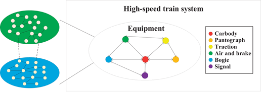
The identification of system-level critical elements is of great practical significance, which is conducive to maintaining the safety and reliability of high-speed railway system. On the one hand, it can support the reliability improvement and optimization during the design stage. On the other hand, it can also reasonably allocate the detection and maintenance resources during the operational phase. Because of the large scale and high complexity of high-speed train systems, system-level critical element identification methods that require a large number of reliability tests and statistical data become infeasible. In practice, however, only a small amount of experimental data, field data and engineering experience information is available (Lin et al., 2018). Therefore, a more cost-effective identification method is needed in high-speed railway systems to achieve operational reliability, availability, maintainability and supportability (Saraswat and Yadava, 2008).
1.2 Related literature
The critical elements of the high-speed train system refer to the unit that plays an important role in maintaining the global topology and normal functions. The importance measure is the common method of system-critical elements identification, which can be roughly divided into the following two types.
1.2.1 Importance measurement based on reliability theory.
In the existing research on the identification of critical elements, important indices of reliability have been widely used. Birnbaum’s importance is a sensitivity analysis method widely used in the field of component reliability (Wang et al., 2004). Critical importance is usually combined with fault tree analysis to measure the impact of failed critical components on system failures (Espiritu et al., 2007; Lambert, 1975). The reliability achievement worth (RAW) importance mainly measures the importance of the component to maintain the current reliability level of the system, and alternately, the reliability reduction worth (RRW) importance is mainly used to analyze the degree of influence on the current reliability level of the system when the component is always unreliable (Bisanovic et al., 2016). Fussell-Vesely’s importance is mainly used to evaluate the influence of a minimal cut set containing at least one failed component on the system reliability (Van Der Borst and Schoonakker, 2001). The Bayesian reliability importance measures the probability that a component fails given that the system fails (Zhu and Kuo, 2014).
In general, the following assumptions are made before the analysis of reliability importance.
Failure probabilities and repair times are independent.
Component states and associated probabilities are known.
However, in real systems, components are interdependent in the process of implementing functions and reliability also affects each other (Dobson et al., 2007). Therefore, for a complex system such as the high-speed train system, it is almost infeasible to accurately obtain information on the reliability importance of each component to identify critical components, which is also uneconomical.
1.2.2 Importance measurement based on complex network theory.
As the groundbreaking work of Watts and Strogatz (1998) regarding small-world networks and Barabási and Albert (1999) regarding scale-free networks, real-word phenomena have begun to be studied from the perspective of actual networks and network theory. Taking components as nodes and connecting relationships as arcs are the main mean of abstracting actual systems into complex networks (Lin et al., 2018; Wang et al., 2017). Kou et al. (2018) proposed a new method that can better use the theory of network flow to represent the network: arcs represent the components, and nodes are the transitive relation. For the distributed and complex electromechanical system, Wang et al. (2016) generated a penetrable visibility graph method that combines the phase space reconstruction method. Topological features include degree centrality (DC), betweenness centrality (BC), closeness centrality (CC), etc (Bonacich, 2007; Brandes et al., 2016; Chen et al., 2012; Du et al., 2015; Hu et al., 2015).
The application of the topological approach to measure importance is quite popular. On the one hand, it has obvious advantages in the analysis of complex systems because it is relatively simple to use. On the other hand, it offers the capability of identifying elements of structural reliability, i.e. network edges and nodes whose failure can induce severe damage to the network through the physical disconnection of its parts. However, the traditional complex network approach only focuses on the topology characteristics of the network and ignores the physical significance of the components (Hines and Blumsack, 2008; Zio and Golea, 2012). In this respect, it is important to possibly overcome these limitations by complementation with more actual characteristic analyzes on components of complex systems (Bompard et al., 2009).
1.3 Contributions
A method of identifying key elements of the CRH2 train system based on integrated importance indices is introduced, which is a meaningful extension of the application of complex network theory to identify key components. Our work makes two important contributions.
A multi-layer multi-granularity network model suitable for the identification of critical elements in the high-speed train system is presented, including virtual nodes and actual nodes. The rules for merging edges of the same component at different layers are given.
Considering the topology structure, actual function and risk characteristics of the high-speed train system, an integrated importance ranking algorithm based on entropy weight and grey relation analysis is proposed. This algorithm compensates for the lack of actual features of the complex network theory.
The rest of this paper is structured as follows: Section 2 describes a multi-layer multi-granularity network model and details the rule of fusion. Section 3 explains the integrated importance ranking algorithm of the proposed network model. A case study is used to verify the effectiveness of the network model and importance ranking algorithm in Section 4. Finally, conclusions are drawn in Section 5.
2. Methodology
2.1 The network model
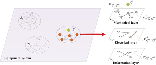
Based on the definition of dependency relationship between elements in train system in Wang et al. (2017), we define the connection relationship between the components in the established network as mechanical connection, electrical connection and information connection. Therefore, the conception of the mechanical layer, electrical layer and information layer is proposed. The multi-layer multi-granularity network S is built as follows:
where Si is subsystem i of the train system, Gi,α, Gi,β and Gi,γ are the mechanical layer, electrical layer and information layer of subsystem i, Vi is the set of nodes of subsystem i, Ei,α, Ei,β and Ei,γ are the set of links of three layers of subsystem i.
where is the virtual node of subsystem i, is the set of real nodes of subsystem i, is the real node s of subsystem i. Note that, nodes in different layers of the same subsystem are identical:
where is the set of links representing affiliation relationships of subsystem i, is the set of links representing action relationships of subsystem i, is the link between and , is the link between and at layer u.
The structure diagram of the network is shown in Figure 2. In the equipment system, each subsystem Si has a virtual node and several real nodes, and two real nodes may have different relationships at the mechanical, electrical and information layers.
2.2 Fusion rules of links of different layers
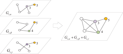
For the constructed multi-layer complex network, fusion rules of edges of the different layer are given (Zhang et al., 2020). With the help of a common vertex, the connections of different layers can be merged. For example, through node 5, and can be merged (Figure 3). If two nodes have connections at different layers, the connections are merged into one. For example, for nodes 3 and 5, and are merged into one.
3. An integrated importance ranking algorithm
An importance ranking algorithm considering the actual function and risk characteristics of the complex network based on the topology structure is proposed.
3.1 Selection and calculation of indices
3.1.1 Indices of topology characteristics.
The topology indicator of component s consists of four indices. Topology degree is the simplest centrality measure of a node in a complex network, and the more links a given node is connected the more important it will be. Topology closeness centrality represents the “closeness” of a node to the others and the larger the value, the more important the node is. Topology betweenness refers to the number of shortest paths through a given node in the complex network, and the larger the value, the more important the component. Topology efficiency measures the network efficiency on the condition that the component s is in failure, and the smaller the value is, the more important it is, which is contrary to the judgment standard of the other three indices:
where ast is the value of the sth row and the jth column of the adjacency matrix, m is the total number of nodes in complex network S; dst is the shortest path between node s and t, which is the number of links between two nodes; both values σab(s) and σab are related to the number of shortest paths between nodes a and b, but the difference is that the former only calculates the shortest paths through node s. The indicator mainly presents the topology characteristic of the complex network. The bigger the value is, the more important the component corresponding to the node is in the topology structure.
3.1.2 Indices of function characteristics.
On the basis of the , the function importance indicator is defined according to the importance of the components to the train operation.
where ωs is the coefficient representing the function importance of node s, and the value can be given through the method of scoring by expert’s experience (Table 1).
Grading standard for evaluating the function importance in the high-speed train system
| Score | [0, 0.3] | [0.4, 0.7] | [0.8, 1] |
|---|---|---|---|
| Standard | Less important | Important | Very important |
On the basis of rich practical experience, experts rank the importance of each node, with scores ranging from 0 to 1. If the value of is large, the corresponding component plays an important role in ensuring the normal operation of the train.
3.1.3 Indices of risk characteristics.
Considering the possibility and impact of the failure, the risk indicator is defined:
where ps is the coefficient of occurrence frequency of node s counted from fault data (Table 2); qsa is the impact on node a after the failure of node s; is the risk shortest path from nodes s to t; ls is the severity of the impact on train operation when node s fails obtained from the historical text data. Note that, the impact on train operation we mentioned here means that the train has to be stopped temporarily and ls is the value of the current state that the node has degraded from the optimal state, where ls ranges from 0 to 100. A larger means that when the corresponding component fails, the greater the impact on train operation.
3.2 Integrated importance measure
An importance ranking algorithm combining the entropy weight method and grey relational analysis is introduced here to measure the integrated importance.
3.2.1 Index preprocessing.
Because the goals and directions of these indices are different, processing all performance values for every component into a comparability sequence is necessary. If there are m components and n index, the sth component can be expressed as Is = (Is1,Is2,⋯,Isx,⋯,Isn), where Isx is the performance value of index x of component s. The term Is can be translated into Ds by use of one of the equations (7)–(8):
Equation (7) is used for the-larger-the-better index and equation (8) is used for the-smaller-the-better index.
3.2.2 Entropy weight calculation.
The concept of entropy is well suited to measuring the utility value of indices to represent the average intrinsic information transmitted for decision-making. In general, the smaller the entropy Ei of a certain index is, the greater the variation degree of the index value is and the more information can be provided, the greater the weight of the index value is. On the contrary, the greater the entropy, the smaller the weight.
where m is the number of actual data for evaluation objects, n is the number of indices selected, fsx is the proportion of the sth component to the xth index, ex is the entropy value of the xth index, wx is the weight of the xth index.
3.2.3 Grey relational analysis.
The state of the components in the high-speed train system is regarded as a grey system, and the critical elements are identified based on the value of correlation degree. The reference sequence fsx is defined as d0x = (dsx,s = 1,2,⋯,m):
where γ(I0x,Isx) is the grey relational coefficient between I0x and Isx; ρ is the distinguishing coefficient, ρ ∈ [0,1]; Γs is the weighted grey relational grade.
4. Numerical example
A typical CRH2 train system is taken as an example to illustrate the feasibility of the model and algorithm proposed in this study. The code is implemented in Ri386 3.4.3, uses Gephi to draw graphics and runs on a 64-bit Windows operating system.
4.1 Data and parameters
The components composing the rail train are more than 40,000 (Kou et al., 2018). To facilitate the analysis, we select some representative elements for study and finally form a multi-layer multi-granularity network composed of 5 virtual nodes and 125 actual nodes (Table 3).
The virtual and actual nodes of the whole network (only partial actual nodes are listed)
| Node type | Node’s label | Component name | Node’s label | Component name |
|---|---|---|---|---|
| Virtual nodes | PANTOGRAPH | Pantograph subsystem | BOGIE | Bogie subsystem |
| TRACTION | Traction subsystem | SIGNAL | Signal subsystem | |
| AIRBRAKE | Air and brake subsystem | – | – | |
| Actual node | 1 | Carbody | 7 | Dropper |
| 3 | Pillar | … … | … … | |
| 4 | Insulator | … … | … … | |
| 5 | Location device | … … | … … | |
| 6 | Catenary | 130 | Close-fitting checker |
Note that, virtual and actual nodes are encoded together in the network construction. For example, the virtual node “PANTOGRAPH” corresponds to the unshown node whose label should be “2” in Table 3.
4.2 Results
4.2.1 Fusion rules of links of different layers.
Taking the bogie subsystem as an example to illustrate the fusion rules. CRH2 train adopts the 4M4T marshaling mode, its motor car uses the SKMB-200 power bogie and the trailer uses the SKTB-200 trailer bogie. According to the structure and fault data of CRH2 bogie and the extraction rules of components, a total of 31 components are extracted as nodes in each layer of the multi-layer network model of the bogie subsystem (Table 4).
The virtual and actual nodes in the bogie subsystem
| Label | Name |
|---|---|
| BOGIE | Bogie |
| 70 | Bogie frame |
| 71 | Wheel |
| 72 | Axle box bearing |
| 73 | Axle box |
| 74 | Axle |
| 75 | Primary vertical vibration absorber |
| 76 | Axle spring |
| 77 | Secondary vertical vibration absorber |
| 78 | Secondary lateral vibration absorber |
| 79 | Anti-yaw vibration absorber |
| 80 | High-speed adjusting valve |
| 81 | Certain pin |
| 82 | Anti-rolling torsion bar |
| 83 | Air spring |
| 84 | Traction rod |
| 85 | Lateral stop |
| 86 | Coupling |
| 87 | Gearbox |
| 88 | Grounding device |
| 89 | Lubrication device |
| 90 | Sand device |
| 91 | Troubleshoot device |
| 92 | Junction box |
| 93 | Speed sensor1 |
| 94 | Speed sensor2 |
| 95 | Speed sensor3 |
| 96 | Speed sensor4 |
| 97 | Speed sensor5 |
| 98 | Accelerate sensor |
| 99 | Gearbox bearing temperature sensor |
| 100 | Axis temperature sensor |
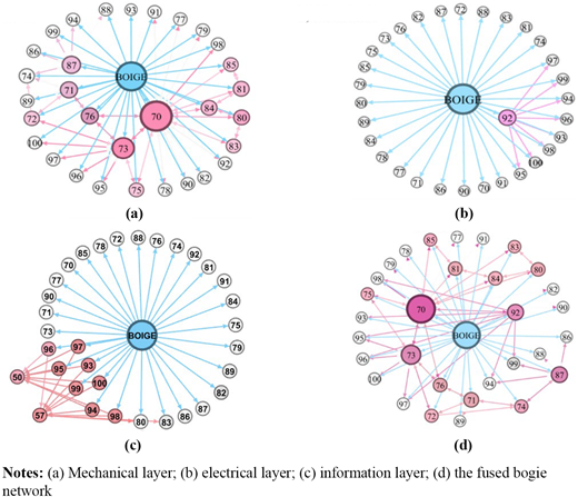
Node Bogie is a virtual node that connecting with all the other nodes belonging to the bogie subsystem, presenting the affiliation relationships between the subsystem and components. In Figure 4, the affiliation connections are blue and the actual connections are in different shades of pink, which is proportional to the degree of each node. In Figure 4(c), the nodes labeled “50” and “57” are motor and main windpipe, which are hidden in the fused bogie network because they are divided into other subsystems. Figure 4(d) is the result of fusing the mechanical layer, electrical layer and information layer, which contains all the connection relationships of the bogie subsystem. The combined network comprehensively considers all connection relationships and greatly reduces the complexity of multi-layer network computing. Next, fusion rules are applied to the complex network of the high-speed train system and critical elements will be identified.
4.2.2 Indices calculation.
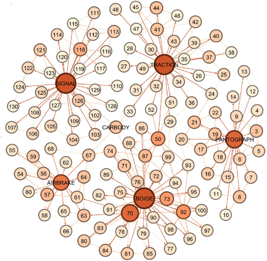
After adopting the fusion rules, the complex network of the high-speed train system has 130 nodes and 370 edges. In Figure 5, the node is colored according to its outdegree value, which reflects the activity of the node in the network (Snijders, 2003). The outdegree value of each virtual node is relatively large because it has affiliation relationships with all actual nodes in its subsystem.
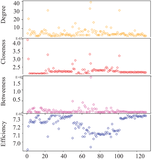
4.2.2.1 Indices in topology characteristics.
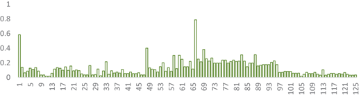
are calculated as shown in Figure 6. The ranking results of importance will be quite different if it is performed according to each index separately, and therefore the topology index Ktopo is of great significance to present the integrated topology importance (Figure 7). The weights of each indicator are: Wtopo = {0.280, 0.281, 0.165, 0.274}. Rank nodes by the value of Ktopo and the top 30 are shown in Table 5.
Nodes in the top 30 of topology importance
| Order | Name | Ktopo |
|---|---|---|
| 1 | Bogie frame | 0.788 |
| 2 | Carbody | 0.584 |
| 3 | Motor bearing | 0.401 |
| 4 | Axle box | 0.383 |
| 5 | Junction box | 0.310 |
| 6 | Gearbox | 0.309 |
| 7 | Brake clamp | 0.303 |
| 8 | Brake cylinder | 0.302 |
| 9 | Axle spring | 0.266 |
| 10 | Axle | 0.255 |
| 11 | Wheel | 0.251 |
| 12 | Pressure cylinder | 0.248 |
| 13 | High-speed adjusting valve | 0.237 |
| 14 | Certain pin | 0.237 |
| 15 | Traction rod | 0.237 |
| 16 | Gearbox bearing temperature sensor | 0.227 |
| 17 | Primary vertical vibration absorber | 0.225 |
| 18 | Coupling | 0.223 |
| 19 | Grounding device | 0.223 |
| 20 | Brake disc | 0.219 |
| 21 | Air spring | 0.217 |
| 22 | Lateral stop | 0.217 |
| 23 | IGBT | 0.215 |
| 24 | Axle box bearing | 0.214 |
| 25 | Accelerate sensor | 0.208 |
| 26 | Main windpipe | 0.202 |
| 27 | Secondary vertical vibration absorber | 0.197 |
| 28 | Secondary lateral vibration absorber | 0.197 |
| 29 | Anti-yaw vibration absorber | 0.197 |
| 30 | Anti-rolling torsion bar | 0.197 |
The value of the bogie frame is the largest (0.788), that is, this component is the most important one from the perspective of the topology structure. This is followed by car body, motor bearing, axle box, etc., and the topology critical components are formed. Overall, the difference of the Ktopo value is obvious in the whole system, the scores of the bogie subsystem and the air-brake subsystem are relatively higher than the other parts. Next, Kfunc and Krisk are calculated separately based on the result of Ktopo.
4.2.2.2 Indices in function characteristics.
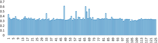
Based on the topology indices and function score, Kfunc is obtained (Figure 8). The weights of each indicator are: Wfunc = {0.272, 0.235, 0.165, 0.328}. Rank nodes by the value of Kfunc and the top 30 are shown in Table 6.
Nodes in the top 30 of function importance
| Order | Name | Kfunc | |
|---|---|---|---|
| 1 | Motor bearing | 0.613 | |
| 2 | Bogie frame | 0.603 | |
| 3 | Axle box | 0.551 | |
| 4 | Brake cylinder | 0.502 | |
| 5 | Wheel | 0.494 | |
| 6 | Gearbox | 0.460 | |
| 7 | IGBT | 0.458 | |
| 8 | Carbody | 0.438 | |
| 9 | Main windpipe | 0.401 | |
| 10 | Contract line | 0.394 | |
| 11 | Bow suspension | 0.392 | |
| 12 | Brake clamp | 0.384 | |
| 13 | Junction box | 0.383 | |
| 14 | Axle spring | 0.377 | |
| 15 | Pressure cylinder | 0.376 | |
| 16 | Axle | 0.369 | |
| 17 | Lower rod | 0.364 | |
| 18 | Pillar | 0.364 | |
| 19 | Underframe | 0.364 | |
| 20 | Carbon slide | 0.363 | |
| 21 | Brake disc | 0.363 | |
| 22 | Catenary | 0.361 | |
| 23 | Support capacitor | 0.358 | |
| 24 | Upper rod | 0.357 | |
| 25 | Gearbox bearing temperature sensor | 0.357 | |
| 26 | Wind cylinder | 0.356 | |
| 27 | Dropper | 0.355 | |
| 28 | Axle box bearing | 0.354 | |
| 29 | Transmission control unit | 0.354 | |
| 30 | Main air cylinder | 0.353 | |
Motor bearing is the most important component on the point of function importance that with the largest value of (0.613), followed by bogie frame, axle box, brake cylinder, wheel, etc. The difference in the Ktopo of the components is significant. In contrast, most components in the network have a high Kfunc with an average of 0.35. That is to say, the components selected in this paper are very important in the process of train operation.
4.2.2.3 Indices in risk characteristics.
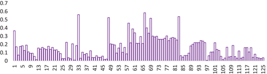
Similarly, Krisk is obtained as shown in Figure 9 and the top 30 are shown in Table 7. The weights of each indicator are:
Nodes in the top 30 of risk importance
| Order | Name | Krisk |
|---|---|---|
| 1 | Bogie frame | 0.584 |
| 2 | IGBT | 0.561 |
| 3 | Gearbox | 0.538 |
| 4 | Motor bearing | 0.525 |
| 5 | Axle box | 0.518 |
| 6 | Brake cylinder | 0.459 |
| 7 | Wheel | 0.401 |
| 8 | Brake clamp | 0.389 |
| 9 | Carbody | 0.366 |
| 10 | Pressure cylinder | 0.341 |
| 11 | Axle box bearing | 0.337 |
| 12 | Certain pin | 0.303 |
| 13 | Axle | 0.301 |
| 14 | Axle spring | 0.299 |
| 15 | Brake disc | 0.296 |
| 16 | Primary vertical vibration absorber | 0.291 |
| 17 | Traction rod | 0.285 |
| 18 | lateral stop | 0.276 |
| 19 | Air spring | 0.276 |
| 20 | High-speed adjusting valve | 0.276 |
| 21 | Anti-yaw vibration absorber | 0.262 |
| 22 | Secondary vertical vibration absorber | 0.262 |
| 23 | Secondary lateral vibration absorber | 0.262 |
| 24 | Coupling | 0.254 |
| 25 | Accelerate sensor | 0.248 |
| 26 | Anti-rolling torsion bar | 0.246 |
| 27 | Gearbox bearing temperature sensor | 0.241 |
| 28 | Transmission control unit | 0.225 |
| 29 | Speed sensor4 | 0.223 |
| 30 | Speed sensor5 | 0.223 |
In terms of the probability of risk and the severity of the consequences, the bogie frame is the most important component, with a value of 0.584, followed by IGBT, gearbox, motor bearing, axle box, etc. The probability of nodes with high Ktopo and Kfunc degenerating to failure is supposed to be small, but once the components fail, the consequences are very serious, so the value of Krisk may be very large such as the bogie frame.
4.2.2.4 The important elements.
The maximum values of the topology index Ktopo, the function index Kfunc and the risk index Krisk are used as the grey-reference. Based on the grey relational analysis, the integrated importance indicator K is obtained and the critical components are obtained (Table 8).
Nodes in the top 20 of integrated importance
| Order | Name | Ktopo | Kfunc | Krisk | K |
|---|---|---|---|---|---|
| 1 | Bogie frame | 0.788 | 0.603 | 0.584 | 0.991 |
| 2 | Motor bearing | 0.401 | 0.613 | 0.525 | 0.789 |
| 3 | Axle box | 0.383 | 0.551 | 0.518 | 0.734 |
| 4 | IGBT | 0.215 | 0.458 | 0.561 | 0.687 |
| 5 | Gearbox | 0.309 | 0.460 | 0.538 | 0.685 |
| 6 | Carbody | 0.584 | 0.438 | 0.366 | 0.660 |
| 7 | Brake cylinder | 0.302 | 0.502 | 0.459 | 0.658 |
| 8 | Wheel | 0.251 | 0.494 | 0.401 | 0.620 |
| 9 | Brake clamp | 0.303 | 0.384 | 0.389 | 0.578 |
| 10 | Pressure cylinder | 0.248 | 0.376 | 0.341 | 0.550 |
| 11 | Axle spring | 0.266 | 0.377 | 0.299 | 0.540 |
| 12 | Axle box bearing | 0.214 | 0.354 | 0.337 | 0.536 |
| 13 | Axle | 0.255 | 0.369 | 0.301 | 0.536 |
| 14 | Certain pin | 0.237 | 0.352 | 0.303 | 0.529 |
| 15 | Brake disc | 0.219 | 0.363 | 0.296 | 0.527 |
| 16 | Traction rod | 0.237 | 0.352 | 0.285 | 0.524 |
| 17 | High speed adjusting valve | 0.237 | 0.352 | 0.276 | 0.521 |
| 18 | Primary vertical vibration absorber | 0.225 | 0.340 | 0.291 | 0.520 |
| 19 | Main wind pipe | 0.202 | 0.401 | 0.215 | 0.517 |
| 20 | lateral stop | 0.217 | 0.345 | 0.276 | 0.516 |
Compare the four tables from Tables 5 to 8, we can get the following conclusions.
Generally, based on a comprehensive analysis of the three indicators of topology, function and risk, the most important element of the CRH2 train system is the bogie frame. The bogie frame is the basic stress point of the bogie and the installation foundation of various components. It has a connection relationship with almost all components of the bogie subsystem, so the topology index value is very high and the integrated importance based on the topological structure is also relatively high, which means that it is a component that requires the focus of the relevant railway department.
Carbody, motor bearing, axle box, gearbox and brake cylinder are ranked in the top 10 in all tables, which means that they are very important and require more attention to keep train operation safely. Here, the car body is defined as a combination of electromechanical components, that is, the train system except for the other five subsystems clearly given in the text.
Most of the key elements of the CRH2 train system identified by complex network theory belong to the bogie subsystem, so this subsystem needs special attention.
5. Conclusions
This study aims to introduce a method for identifying critical elements of the CRH2 train system based on complex network theory. A multi-layer multi-granularity network model suitable for the CRH2 train system is presented, including virtual nodes and actual nodes. Based on the network characteristic index, entropy weight and grayscale theory, the integrated importance ranking algorithm considering the three dimensions of topology, function and risk is proposed. Finally, a CRH2 train system is provided. Compared with the identification results by topology, function and risk indicator separately, the critical elements identified by the integrated importance ranking algorithm is more reasonable because it comprehensively takes into consideration the characteristics of the complex network in three dimensions. The most important element of the identified key elements is the bogie frame and most of the components belong to the bogie subsystem of the train, which also means that this subsystem is the one that needs the most attention of relevant staff.
In summary, the critical elements identification method based on complex network theory proposed in this paper enables decision-makers to not only improve train reliability in the design phase but also allocate maintenance resources more reasonably during the operation phase. At the same time, this method has universality and can be applied to the identification of critical elements of any other type of train on the basis of corresponding data.
This study is funded by the National Key Research and Development Program of China (2016YFB1200401).

