
1-20 of 18109
Keywords: ORDB
Close
Follow your search
Access your saved searches in your account
Would you like to receive an alert when new items match your search?
Journal

A source of theoretical and application techniques for scholars and practitioners to allow organizations to benchmark their performance and identify the best practices in organizational management.
Journal Articles
Benchmarking: An International Journal 1–29.
Published: 08 September 2026
Includes: Supplementary data
in Coordination versus governance in decentralized supply chain partner selection
> Benchmarking: An International Journal
Published: 08 September 2026
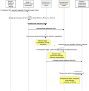
Figure 1 Comparative research design and analytical flow A flowchart illustrating the comparative research design and analytical flow for evaluating decentralized decision architectures. A flowchart illustrating the comparative research design and analytical flow for evaluating decentralized d... More about this image found in Comparative research design and analytical flow A flowchart illustrating...
in Coordination versus governance in decentralized supply chain partner selection
> Benchmarking: An International Journal
Published: 08 September 2026
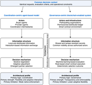
Figure 2 Comparison of alternative decentralized decision architectures A diagram comparing two decentralized decision architectures. The diagram compares two decentralized decision architectures: the coordination-centric agent-based model and the governance-centric blockchain-enabled system. ... More about this image found in Comparison of alternative decentralized decision architectures A diagram...
in Coordination versus governance in decentralized supply chain partner selection
> Benchmarking: An International Journal
Published: 08 September 2026
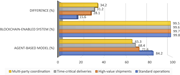
Figure 3 Enforcement reliability by operational context A bar graph comparing the performance of blockchain-enabled systems and agent-based models across different operational contexts. A horizontal bar graph compares the performance of blockchain-enabled systems and agent-based models across ... More about this image found in Enforcement reliability by operational context A bar graph comparing the...
in Coordination versus governance in decentralized supply chain partner selection
> Benchmarking: An International Journal
Published: 08 September 2026
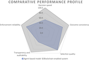
Figure 4 Comparative performance profile of the two decision architectures A radar chart comparing the performance profiles of two decision architectures. The image is a radar chart that compares the performance profiles of two decision architectures: an agent-based model and a blockchain-enab... More about this image found in Comparative performance profile of the two decision architectures A rada...
in Internal benchmarking in hotel chains: a slack-based DEA framework for economic-operational and environmental performance
> Benchmarking: An International Journal
Published: 04 September 2026
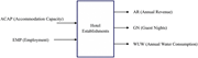
Figure 1 Inputs and outputs considered in the baseline specification. Source: Authors' own elaboration A diagram illustrating the inputs and outputs of hotel establishments. A flowchart representing the inputs and outputs of hotel establishments. The diagram shows that hotel establishments rec... More about this image found in Inputs and outputs considered in the baseline specification. Source: Author...
in Internal benchmarking in hotel chains: a slack-based DEA framework for economic-operational and environmental performance
> Benchmarking: An International Journal
Published: 04 September 2026
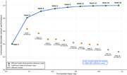
Figure 2 Conceptual DEA frontier for hotel benchmarking. Efficient hotels are represented on the illustrative efficient frontier, whereas inefficient hotels are positioned below the frontier according to their SBI inefficiency scores. The figure is intended as a visual representation of the benchm... More about this image found in Conceptual DEA frontier for hotel benchmarking. Efficient hotels are repres...
in Internal benchmarking in hotel chains: a slack-based DEA framework for economic-operational and environmental performance
> Benchmarking: An International Journal
Published: 04 September 2026
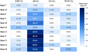
Figure 3 Heatmap of percentage improvement targets by variable for inefficient hotels, ordered by benchmarking rank. Darker cells indicate larger required adjustments, whereas 0% indicates that no adjustment is required. Percentages are computed relative to each hotel's observed value. Source: Aut... More about this image found in Heatmap of percentage improvement targets by variable for inefficient hotel...
Journal Articles
Benchmarking: An International Journal 1–31.
Published: 04 September 2026
Journal Articles
Benchmarking: An International Journal 1–21.
Published: 04 September 2026
Includes: Supplementary data
in Digital agility and business resilience: identifying employee and organisational enablers across resilience states through a hybrid decision analytic approach
> Benchmarking: An International Journal
Published: 04 September 2026
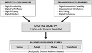
Figure 1 Conceptual framework. Source: Authors’ own work A conceptual framework diagram illustrating the relationship between employee-level and organizational-level enablers, digital agility, and business resilience states. A conceptual framework diagram illustrating the relationship between employee-level and organizational-level enablers, digital agility, and business resilience states. The diagram is structured into three main sections. At the top, there are two boxes labeled 'Employee-Level Enablers' and 'Organisation-Level Enablers.' The 'Employee-Level Enablers' box includes Digital Leadership, Digital Self-Efficacy, Digital Fluency, and Digital Mindset. The 'Organisation-Level Enablers' box includes Digital Innovation Capability, Organisational Mindfulness, Risk Taking, and Digital Turbulence. Arrows from both boxes point towards a central box labeled 'Digital Agility (Higher-order Dynamic Capability).' An arrow from the 'Digital Agility' box points downward to another box labeled 'Business Resilience States,' which includes the states Sense, Adapt, Thrive, and Transform. More about this image found in Conceptual framework. Source: Authors’ own work A conce...
in Digital agility and business resilience: identifying employee and organisational enablers across resilience states through a hybrid decision analytic approach
> Benchmarking: An International Journal
Published: 04 September 2026
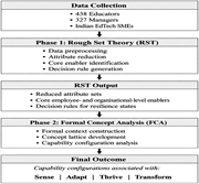
Figure 2 Methodological flowchart. Source: Authors’ own work A flowchart illustrating the methodological process for analyzing resilience states using Rough Set Theory and Formal Concept Analysis. The flowchart begins with data collection from 438 educators, 327 managers, and Indian EdTech SMEs. Phase 1 involves Rough Set Theory (RST), which includes data preprocessing, attribute reduction, core enabler identification, and decision rule generation. The output of this phase includes reduced attribute sets, core employee- and organizational-level enablers, and decision rules for resilience states. Phase 2 involves Formal Concept Analysis (FCA), which includes formal context construction, concept lattice development, and capability configuration analysis. The final outcome of this process is the identification of capability configurations associated with sense, adapt, thrive, and transform. More about this image found in Methodological flowchart. Source: Authors’ own work A f...
in Digital agility and business resilience: identifying employee and organisational enablers across resilience states through a hybrid decision analytic approach
> Benchmarking: An International Journal
Published: 04 September 2026
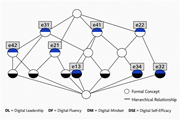
Figure 3 Employee-level FCA concept lattice for the sense resilience state. Code legend: e31 = Digital self-efficacy–low; e41 = Digital mindset–less; e22 = Digital fluency–average; e42 = Digital mindset–somewhat; e21 = digital fluency–low; e13 = Digital leadership–preferred; e34 = Digital self-efficacy–very high; e32 = Digital Self-efficacy–Average. Note: Nodes represent formal concepts generated through Formal Concept Analysis (FCA), while connecting lines indicate hierarchical relationships among the concepts. Node labels identify the formal concepts derived from the retained decision rules. Source: Authors’ analysis A diagram of a concept lattice for employee resilience states. A diagram of a concept lattice for employee resilience states. The lattice includes nodes representing formal concepts generated through Formal Concept Analysis (FCA). Each node is labeled with a code that corresponds to different levels of digital self-efficacy, digital mindset, and digital fluency. The nodes are connected by lines indicating hierarchical relationships among the concepts. The labels include e31 for digital self-efficacy low, e41 for digital mindset less, e22 for digital fluency average, e42 for digital mindset somewhat, e21 for digital fluency low, e13 for digital leadership preferred, e34 for digital self-efficacy very high, and e32 for digital self-efficacy average. The diagram visually represents how these concepts are interrelated within the context of employee resilience. More about this image found in Employee-level FCA concept lattice for the sense resilience state. Code leg...
Journal Articles
Benchmarking: An International Journal 1–33.
Published: 02 September 2026
in Barriers to Agile Supply Chain Management 4.0 adoption in Indian automotive OEMs: a case-based empirical analysis using SWARA-GRA approach
> Benchmarking: An International Journal
Published: 02 September 2026
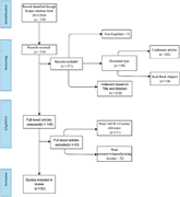
Figure 1 PRISMA flowchart for barriers identification A flowchart illustrating the systematic literature review process for identifying barriers to ASCM 4.0 implementation in automotive manufacturing supply chains. A flowchart illustrating the systematic literature review process for identifyi... More about this image found in PRISMA flowchart for barriers identification A flowchart illustrating th...
in Barriers to Agile Supply Chain Management 4.0 adoption in Indian automotive OEMs: a case-based empirical analysis using SWARA-GRA approach
> Benchmarking: An International Journal
Published: 02 September 2026
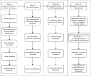
Figure 2 Adopted research framework A flowchart illustrating the research framework for analyzing barriers to ASCM 4.0 implementation. The flowchart outlines a research framework for analyzing barriers to ASCM 4.0 implementation. It consists of four phases: Phase I, Phase II, Phase III, and Ph... More about this image found in Adopted research framework A flowchart illustrating the research framewo...
in Barriers to Agile Supply Chain Management 4.0 adoption in Indian automotive OEMs: a case-based empirical analysis using SWARA-GRA approach
> Benchmarking: An International Journal
Published: 02 September 2026
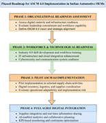
Figure 3 Phased ASCM 4.0 implementation roadmap for Indian automotive OEMs A four-phase roadmap for ASCM 4.0 implementation in Indian automotive OEMs. A flowchart detailing a phased roadmap for ASCM 4.0 implementation in Indian automotive OEMs. The flowchart is divided into four phases. Phase ... More about this image found in Phased ASCM 4.0 implementation roadmap for Indian automotive OEMs A four...
Journal Articles
Benchmarking: An International Journal 1–47.
Published: 01 September 2026
Includes: Supplementary data
in Key enabling constructs and performance outcomes of an Integrated Sustainable Green Lean Six Sigma Agile Manufacturing System in Indian manufacturing organizations
> Benchmarking: An International Journal
Published: 01 September 2026
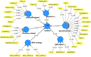
Figure 1 Path coefficients of enabling constructs model. Source: Authors’ own work A diagram representing the relationships between various constructs in an enabling constructs model. A diagram representing the relationships between various constructs in an enabling constructs model. The diagr... More about this image found in Path coefficients of enabling constructs model. Source: Authors’ own work ...

